1
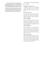
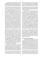
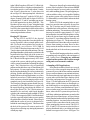
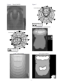
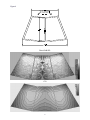
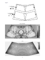
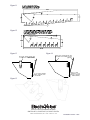
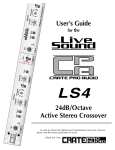
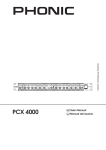
EVI-12, EVI-15 and EVI-28
Loudspeaker Systems
Applications Guide
In a nutshell, here are the major advantages of
the new EVI systems:
Welcome to the world of Vari Intense® horn
technology from Electro-Voice. This Applications
Guide is not intended as a “very intense” description of installation procedures, but more as a partial
description of applications and a discussion with
the designer to help you understand this revolutionary technology and use the Electro-Voice Vari Intense® systems to install better-sounding systems
and significantly reduce time and material costs.
• Rectangular coverage pattern.
Traditional horns deliver an elliptical pattern
to the floor. VI horns deliver a rectangular
pattern, which helps to fill in the corners of
the room. No more costly delay lines or cheap
seats!!
• Even SPL front-to-back.
The unique, patented throat and flare structure of the VI horn delivers a 6-10 dB hotter
signal to the rear of the room, eliminating earstrain at the back of the seating area and painful ears at the front.
• Greater Intelligibility.
VI horns deliver sound to fill only the
floorplan, providing uniform direct-field SPL
and an order of magnitude less energy into
the reverberant field. This provides an increase
in mid- to high-frequency intelligibility of 6 dB
in most applications.
• One horn replaces two.
With VI technology we’ve eliminated the destructive interference which occurs between
long- and short-throw horns. We’ve also eliminated the cost of a properly designed two-horn
system which must include another power amplifier channel for good power control and
impedance matching.
• Labor savings in the box.
With structural rigging from the factory, these
systems will fly more conveniently and in less
time than many competitive products. In addition, less time is spent on the aiming and repositioning that is required with traditional longthrow/short-throw horn combinations. This
will save you additional money.
1
Installation procedures for any conventional
loudspeaker are fairly well-defined and easy to understand: find an appropriate hanging height and
position that affords a clear path to the listening area
(such as above the center of a stage or above the
lectern in a church), and aim the loudspeaker towards the center or just to the rear of center of the
room. With this method you hope to cover the
majority of the room with fairly consistent sound,
but the mid and high frequencies never seem to fill
perfectly. It is frequently aimed a little too far back
and there is a large amount of slap echo, or the
front row is too loud, the back row too soft and the
front and back row corners sound muted due to a
lack of high-frequency energy. Other solutions to
filling the room have been suggested and implemented, including a dual-horn format (one long
throw and one short throw). This method works
fairly well, but encounters several problems: the
added expense of another horn/driver combination;
the vastly increased time to physically install and
then tune the level and aiming of two horns; the inevitable destructive interference patterns throughout the listening area; the expense of another amplifier channel to achieve correct impedance matching; and the need for a very aesthetically clean installation, with no odd-looking (to the customer)
dangling horns. Another solution is to have a horn
that is variable angle, in order to throw a narrow
pattern to the back of the room. The problem with
this concept is that this doesn’t take into account
the drop in SPL between the near throw (about 25
feet) and the far throw (about 70 feet), so the high
frequencies are about 10 dB down in the back of the
room. To solve all of these problems, the Vari Intense® horns were invented, yet another innovation
in the long tradition of Electro-Voice. When properly
aimed, the Vari Intense® horns can provide extremely
even SPL throughout an entire room, filling in the
corners without pushing too much energy at the
back wall, thus avoiding slap echo. The rules of
fixed installation have just changed...
The Electro-Voice EVI-12, EVI-15 and
EVI-28 enclosures are the first in a new generation
of problem-solving systems. The new systems are
designed as a package, with easy mounting, refinishing ability, lightweight, compact and unobtrusive
size and shape and the classic musical sound that
Electro-Voice is known for. The new small-format
VI horn maintains consistent directional control
down to 2,000 Hz. In the EVI-12 and EVI-15 the
VI horn is optimally crossed over to an specially
angled woofer. Note: the 12-in. driver in the EVI12 is at a different angle than the 15-in. driver in the
EVI-15, optimizing the floor pattern with the differing directivities of the two drivers. In the EVI-28,
the VI horn is crossed over to a pair of verticallyarrayed 8-inch woofers with a proprietary technique
that provides delay, amplitude and frequency shading to the two woofers.
The EVI-12, EVI-15 and EVI-28 systems are
installed just like any conventional loudspeaker,
keeping in mind a few simple guidelines. Let me
preface these guidelines with a simple but important comment: the VI systems are extremely versatile and will work in a large variety of applications.
They will work well with tall ceilings, short ceilings,
rectangular rooms, slightly trapezoidal rooms and a
whole host of odd shapes so long as the coverage
area is fairly close to rectangular. The larger
EVI-12 and EVI-15 have been tested in rooms with
12-foot ceilings and performed very well, although
with reduced width of throw. A single EVI-12
was installed in a room 75-foot by 150-foot and an
average RT60 of 4.5 in the mid band and performed
very well with good intelligibility and a minimum of
slap echo. It has been thought in the past that if the
floor pattern does not fit the VI horn exactly, then it
cannot be used at all. This is not the case, and if it
were the case, we could not use standard constantdirectivity horns in most applications either. The
larger VI systems have an “optimum” room that is
approximately twice the height in width and three
times the height in length. This is the ideal condition, but the figures and descriptions that follow
should give you a good feel for the wide-range capabilities of the systems.
EVI-12 and EVI-15 Installation:
The nominal floorplan that the system will
cover with equal SPL is approximately two “units”
wide by three “units” long, where the height of the
loudspeaker defines the size of the “unit.” For example, if the loudspeaker is 18 feet above the floor, it
will typically cover a floorplan of about 36 feet wide
by 54 feet long. In this typical installation (see Figure 1), the back panel of the loudspeaker is mounted
approximately 0.6 units (about 11 feet) back from
the first row and has a nominal angle of the top of
the enclosure parallel to the floor or slightly tilted
back (2 to 3 degrees). For rooms that are much
longer than normal, the VI systems are very easy to
aim and position to fill the entire length. Experiments in actual listening rooms have shown that with
2
the same mounting height of 18 feet, but with the
front of the enclosure tilted up by approximately
10° (see Figure 2), the total floorplan now encompassed the same 36 foot width, but at least 64 feet
in length, an additional 10+ feet of extension. Of
course, the front row position has moved back
about 5 feet with the change in angle as shown, but
this is easy to account for when initially positioning
the system (and is exactly what happens if you take
a conventional system and change the angle). For
rooms that are closer to square, tilting the loudspeaker system down by 15° provides a very clean
square pattern. In this case, the offset to the first
row is about 0.25 times the height of the system.
For example, a tall, square room is about 60 feet
wide, and only 65 feet long. Tilting the enclosure
down by 15° at a 30 foot mounting height makes a
60 foot wide by 60 foot long pattern. The offset to
the first row is 0.25 multiplied by the 30 foot height,
or about 7.5 feet forward from the back of the enclosure. Minor adjustments in aiming will make the
SPL fill the room very evenly with no loss in tonality
in the corners and high overall intelligibility.
By contrast, a typical two-way system with a
60° x 40° CD horn in the same mounting location as
Figures 1 and 2 (see Figure 3) produced a floor plan
that sounded tonally fairly consistent with a 20- to
24-foot width and 30-foot depth with an offset of
nine feet to the front row. On paper, this seems like
adequate performance, but in the room it has very
noticeable (6 dB or greater) variation in overall level
from side to center, and in some aiming cases over
10 dB of variation from front to back as well as a
pronounced lemon shape. The sides of the first
three to five rows in a church and the last few rows
were noticeably muted and much lower in overall
level. As mentioned before, a two-horn system can
work fairly well, but the physical offsets required
for installation inevitably result in some amount of
destructive interference throughout the room
(see Figure 4). Figure 4 was produced using a
90° x 40° CD horn aimed down by 65° and a
60° x 40° horn aimed down by 30°. The actual
physical offsets were used to simulate the floor
response in direct-field SPL. The displayed figure
agrees very well with the measured response, showing a 14-dB variation at 4kHz in a distance of 3 feet
horizontally. Tonal changes as a result of interference pattern change versus frequency were clearly
audible in an acoustically well-behaved room, but
were overall much less audible than for a single system with a conventional CD horn. Locating drivers
and horns closer together than possible with medium-format horns will produce somewhat better
results, but will always result in fairly severe lobing.
Polar measurements in 2° increments show the
lobing very well, but the smoothing required for translation to the EASE 10° resolution database will eliminate the vast majority of peaks and dips, resulting
in what appears to be a fairly smooth simulation. In
contrast, the new VI systems have no problems with
interference, and maintain very good tonality even
far to the sides and to the back, outside the “equalSPL” pattern area. This effect is due to the precise
matching of directivities in the midrange and treble,
giving a consistent (although noticeably quieter) frequency response out to nearly 50 feet in width and
65–70 feet in length from the same 18-foot height
and 0° aiming angle. This has the advantage of providing a much more uniform power response into
the reverberant field, ensuring that the inevitable
reflections (minimized by the VI concept) are consistent in tonal quality.
EVI-28 Installation:
The EVI-28 makes use of the same high-frequency horn as the EVI-12 and EVI-15, but includes a pair of high-power, high-efficiency 8” woofers in a very compact package. The system is provided with a 2,000-Hz passive crossover featuring
tweeter protection and a proprietary passive equalization circuit that provides frequency-shading, amplitude-shading and time delay to the two woofers.
An Acoustic Lens Filter on the grille helps to eliminate spurious lobes and provides a degree of acoustic loading. These features heavily modify the polar
response of the two woofers, providing an extremely
uniform polar pattern with a shape that matches the
VI horn’s unique SPL profile. They also smooth
the transition between woofers and the horn to minimize horizontal lobes, providing amazingly even
coverage through the crossover point. This extends
the VI characteristic down to 500 Hz in an extremely
compact enclosure.
The high-frequency horn in the EVI-28 is
mounted tilted 15° back relative to the EVI-12
and EVI-15. Along with the polar steering in the
woofer’s crossover, this arranges the dispersion for
long throws relative to the mounting height. The
recommended operational vertical angle is minus
5°from the top surface of the enclosure to minus
45°, defining a maximum used vertical dispersion
of 40°. The standard aiming of the system when it
3
Q vs. Intelligibility:
The “Q” of a system is a good measure of the
system’s directivity, and in some ways a good measure of whether the system’s in-room response will
be consistent across the frequency range. A typical 12-inch two-way system with a 60o x 40o horn
will maintain a fairly constant Q from 16-30 or
12-15 dB (normally about 26, or 14dB) from
3,000–20,000 Hz, and a 90o x 40o a Q of 13-15
(11-12dB). Very-high-directivity horns such as a
40o x 20o will have an average Q in the range of
45 (16.5 dB), and very-low-directivity horns like a
120o x 40o will have a Q of 7-9 (8.5-9.5 dB). It is
generally thought that a high-directivity horn will
have greater intelligibility across a given pattern area
than a lower-Q device, and this is true in most cases.
Also true in most cases is that a standard horn pattern will not fill a typical floorplan, thus drastically
reducing the effectiveness of the higher Q. In direct
comparison, the VI horn pattern will fill a majority
of floorplans with direct-field sound rather than relying on reverberant energy to “fill in the gaps” in
overall sound quality and quantity. The Q of the VI
systems are very consistent from 1,000–20,000 Hz,
with a range of 10-18 (10-12.5 dB) and an average Q of 13.5 (11.5dB) or consistent with the overall
directivity of a 90o x 40o system. This might lead
you to believe that the VI systems are “low-Q” and
inappropriate for highly reverberant rooms, but the
plots of the direct-field SPL and its accompanying
C50 ratio show a significant advantage to the VI
system over a conventional 60o x 40o system. As we
all know, high Q only helps when the polar response
fits into the listening space as closely as possible.
Please keep this in mind when using Q as a benchmark for system intelligibility. For those unfamiliar
with the term C50, it is a measure of intelligibility
defined by the acoustic power in the room in the
first 50 msec divided by the power from 50 msec
to infinity, expressed in dB. The minimum recommended level of intelligibility is 0 dB, roughly equivalent to 10% Alcons.
is mounted above a flat floor is with the top of the
enclosure parallel to the floor. In this orientation,
the system will provide even SPL over a floorplan
that is approximately twice as wide as the mounting
height, and five times as long. Tilting the enclosure
down by approximately 10- to 15° relative to the
slope of the floor will produce a floorplan the same
as an EVI-12 or EVI-15. At the standard aiming,
the 45° nearfield operational angle defines an approximate offset to the first useable row of one-half
the height of the speaker system above the listening
plane.
In a typical installation, the top surface of the loudspeaker will point slightly above the head height of
the furthest targeted seating or standing area. This
will ensure the minimum amount of slap echo from
the back wall. In an under-balcony situation, the
sharp cutoff above the zero degree axis prevents
early ceiling reflections from causing interference
patterns in the listening area. Since an EVI-28 has
a very smooth and rapid drop-off towards directly
below the cabinet, you can actually stand right in
front of the speaker (see Figure 12) without ear
strain or heavy microphone feedback. The remarkable absence of lobes to the rear allows the system
to be mounted directly overhead to target a particular area without disturbing the audience below
or behind the cabinet.
For example, FIGURE 11 shows a typical underbalcony application that has a floor with an upward
slope of 5°. The speaker is mounted 10 feet above
the seated head height, so the horizontal width is
fixed at approximately 20 feet. The enclosure is
tilted back by 5° to provide a 50-foot throw, with
the outskirts of the pattern filling in the rear aisle
area with tonally accurate but reduced overall SPL.
If the under-balcony seating area is only 35 feet
deep, then the enclosure should be tilted down by
about 10° relative to the floor in order to prevent
excess slap echo and preserve intelligibility.
Figure 12 shows a typical small-room application,
perfect for a 20-foot by 30-foot boardroom or
meeting hall. In this case, the head height is actually
defined by a standing height of approximately 6 feet,
so the long-throw axis should be very close to horizontal. Then the included 40 degree angle points
directly towards the entire listening area, minimizing
slap echo while retaining a full width, high intelligibility and even SPL throughout the listening area.
A Note on Simulation Software:
Data files for AcoustaCADDTM and EASETM
are available from Electro-Voice’s BBS, by special
request or on Electro-Voice’s Website (http://
www.electrovoice.com). The figures have all been
produced in EASE, but with the current 10° resolution of the software, much of the 2° resolution data
we collect has been lost in the required averaging
translation to the 10-degree format. The net result
4
is that 3dB of long-throw SPL and 1.5-2dB of sidefill level has been lost. A higher resolution data file
is needed to provide a “real world realistic” simulation. Figure 5 shows the raw 2° polar data with
the averaged 10° data superimposed. Also shown
are floorplans from our 2° modeler, DCSO, the 5degree AcoustaCADD and 10-degree EASE. By
comparing the 2°, 5° and 10° resolution you can easily see the apparent loss in direct-field SPL. This
loss shows up as a series of “steps” along the length
of the room and an artificially narrowed throw with
less SPL in the corners than would be achieved in a
real-world installation. Please keep this in mind
when using simulation software.
Please note: the pull-up location on the lower
section of the back panel of the enclosure MUST
be used to hang the system in order to provide a
safe, stable mounting system. The pull-up point provides an additive safety, as it is capable of holding
the speaker system with a safety factor of at least
5:1 in the unlikely event of a failure in the main loadbearing system.
For the EVI-28, the mounting holes are positioned very near the center of gravity for easy aiming. The U-brackets may be rotated all the way
around the back of the enclosure, allowing easy installation and aiming. The maximum vertical angle
that may be reached is approximately 35°, less if
the loudspeaker is mounted flush against a ceiling.
In this case, the enclosure may be rotated upwards
by at least 15°, more than sufficient for nearly any
application (see Figure 15). The brackets are supplied with friction washers that will prevent the enclosure from rotating over time, but to be absolutely certain, the installer should use a set screw in
the threaded hole to fix the enclosure permanently
in position.
The described hanging methods are rated for
suspending only one speaker (with a minimum of
an 8:1 safety factor). Hanging any additional
weight from the speaker will exceed its strength
rating and create an unsafe condition.
Hanging EVI Systems:
For the EVI-12 and EVI-15 the physical
mounting of the systems have been designed to be
as easy as possible, with two simple options available. By far, the easiest solution is to use the optional sturdy, cost effective EVI-12MB or
EVI-15MB U-Brackets that mount to the 3/8-16
T-nut locations on the sides of the enclosure. The supplied forged-shoulder eyebolt must be used in the t-nut
location on the lower back side of the system as a
pull-up point (see figure 13). With this arrangement,
the U-Bracket holds approximately 80% of the
weight of the system, and the pull-up point provides a convenient method of adjusting the aiming
angle. The U-Brackets have easy-to-install bolt
patterns and include three sets of OmniMount 100
bolt patterns. For most applications, this will be
the preferred methodology as it is fast, aesthetically
pleasing, flexible and inexpensive. However, this
method will not work in all applications, so we have
included a second set of T-nut locations on the top
of the enclosure so that the hanging cables can be
completely out of view from below (see Figure 14).
The front pair of hanging points should carry approximately 50 lbs of the enclosure’s weight, with
the required pull-up point taking the balance of
the weight (about 5 lb). The T-nut locations are
intended to be used only with forged shoulder
eyebolts with a minimum tensile strength of 350 kg
(770 lb). The inexpensive EBK-1 kit includes three
eyebolts, especially helpful when access to quality
forged shoulder eyebolts is limited. Please keep in
mind that the center of gravity is designed to be
behind the main hanging points. This means that
the back of the system will rotate as much as 50
degrees down, allowing easy aiming adjustment to
virtually any angle.
A Sampling of EVI Applications:
Now that the technical details are covered,
here are a few ideas on applications that the EVI
systems will cover with far more uniform sound and
lower overall cost than any conventional enclosure.
The first and most obvious application is in a church
or some other well-defined space that has a fairly
tall ceiling, and proportions of roughly 2 x 3 (see
Figure 1). In this application, the EVI systems can
easily replace a central cluster or distributed system with a single low-cost enclosure and still maintain a more uniform sound distribution. Figure 2
shows a similar room, but with a somewhat longer
throw, where the EVI systems also perform very
well. Many auditoriums and theatres are much wider
than a typical set of church pews, so Figure 6 shows
a fairly standard auditorium floor plan and possible
mounting locations. Any interference between the
systems will be concentrated in the center aisle,
where sound quality is not as critical. The EVI-12,
EVI-15 and EVI-28 systems are also ideal for replacing distributed arrays, providing much more
uniform coverage at a lower cost. See Figure 7 for
5
replace a distributed system along a very long, fairly
wide corridor where very high SPLs are not
required on a continuous basis (such as an airport
concourse with 15 to 20 foot ceilings, where a
speaker would be placed about every 75 feet). See
Figure 10 for approximate mounting locations and
floorplan coverage.
These are but a few of the widely varied
applications where the new EVI-12, EVI-15 and
EVI-28 systems will easily outperform a conventional system. The extremely uniform coverage of
the systems are fairly insensitive to placement, require only a few simple calculations to find the best
mounting location, and the aiming angle is no more
or less sensitive than a conventional loudspeaker.
This makes installation nearly foolproof. Even
installation in non-optimal conditions will produce
remarkably even coverage and high intelligibility.
an idea on how the same auditorium floor plan could
be easily covered in a surround-style arrangement
with just two EVI systems per side rather than four
distributed arrays. Although not providing the highest intelligibility or smoothest response, it is applicable to cinemas and some musical preferences.
This has the advantages of cutting installation time,
amplifier channels, additional delay lines and at the
same time providing superior coverage.
A gymnasium is another perfect application
for the EVI systems, covering each grandstand from
a pair of centrally located EVI systems (see Figure
8). In addition, you can cover the entire gymnasium from either a single lengthwise-oriented system or with a pair of widthwise-spaced systems
with lower-SPL coverage on the floor of the
gymnasium than in the stands, so the players are
not disturbed by announcements (see Figure 9).
When the EVI-12 and EVI-15 systems are
tilted up approximately 15°, their coverage pattern
lengthens to match a level EVI-28 at 5 times the
height. In such cases the systems work very well to
As questions arise, you may feel free to contact us at 800/234-6831, or FAX at 616/695-1304.
NOTE: All figures are direct-field SPL and C50 produced in EASE with interference turned
on when applicable. All plots depict the intended listening areas only, and do not include the
“offset distance” to the first row. For example, the first set of plots on figure 3 depict the same
54’ x 36’ area as figure 1. See notes on simulation software.
Figure 1
EVI SYSTEM MOUNTED
AT 18’ HEIGHT AND
0° AIMING ANGLE
(TOP PARALLEL TO FLOOR)
Direct Field SPL
6
C50
Figure 2
EVI SYSTEM MOUNTED
AT 18’ HEIGHT AND
+10° AIMING ANGLE
TILTED BACK
FROM FLOOR
Direct Field SPL
C50
Figure 3
CONVENTIONAL 60X40 SYSTEM
MOUNTED AT 18’ HEIGHT AND
AIMED ABOUT 30° DOWN
Direct Field SPL
C50
CONVENTIONAL 60X40 SYSTEM
MOUNTED AT 18’ HEIGHT AND
AIMED ABOUT 25° DOWN
Direct Field SPL
C50
7
Figure 4
Direct Field SPL
Figure 5
Horizontal Polar
R aw
S moothed
AcoustaCADDTM Direct Field SPL
Vertical Polar
Raw
S moothed
EASETM Direct Field SPL
DCSO Direct Field SPL
8
Figure 6
EVI SYSTEM MOUNTED
AT 20’ HEIGHT AND
8° AIMING ANGLE
Direct Field SPL
C50
9
Figure 7
EVI SYSTEM MOUNTED
AT 18’ HEIGHT AND
-10° AIMING ANGLE
EVI SYSTEM MOUNTED
AT 22’ HEIGHT AND
-10° AIMING ANGLE
Direct Field SPL
C50
10
Figure 8
EVI SYSTEM MOUNTED
BACK-TO-BACK
AT 30’ HEIGHT AND
+5° AIMING ANGLE
Direct Field SPL
C50
11
Figure 9
EVI SYSTEM MOUNTED
AT 25’ HEIGHT AND
15° AIMING ANGLE
Direct Field SPL
C50
12
Figure 10
2 EVI SYSTEM MOUNTED
BACK-TO-BACK AT 40’ HEIGHT
AND +10° AIMING ANGLE
C50
Direct Field SPL
13
Figure 11
Figure 12
Figure 14
Figure 13
BOLTS AND CABLING/CHAINS MUST
BE RATED FOR OVERHEAD LIFTING
(NOT SUPPLIED)
BOLTS AND CABLING/CHAINS MUST
BE RATED FOR OVERHEAD LIFTING
(SEE TEXT)
3/8-16 FORGED SHOULDER
EYEBOLT (SUPPLIED) WITH
PULL-UP STRAP
PULL-UP STRAP
ATTACHED TO 3/8-16
FORGED SHOULDER
EYEBOLT (SEE TEXT)
Figure 15
600 Cecil Street, Buchanan, MI 49107
800/234-6831, 616/695-6831, 616/695-1304 Fax
©Telex Communications, Inc. 1998 • Litho in U.S.A.
Part Number 534762—9822