1
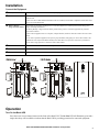
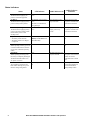
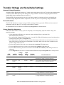
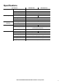
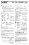
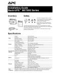
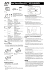
Installation and Operation Manual Back-UPS® BX800CI-RS/BX1100CI-RS Safety and General Information bu001c Inventory This unit is intended for indoor use only. Do not operate this unit in direct sunlight, in contact with fluids, or where there is excessive dust or humidity. Be sure the air vents on the UPS are not blocked. Allow adequate space for proper ventilation. The battery typically lasts for two to five years. Environmental factors impact battery life. Elevated ambient temperatures, poor quality AC power, and frequent short duration discharges will shorten battery life. Connect the Back-UPS power cable directly into a wall outlet. Do not use surge protectors or extension cords. Connect the Battery Connect the battery connector prior to using the UPS. Pull the battery connector handle down. Then push the connector into the UPS. The battery charges fully during the first 10 hours while the Back-UPS is operating on AC power. Do not expect full runtime capability during the initial charge period. There are no serviceable parts in the Back-UPS. Do not attempt to open or repair the Back-UPS as this will void the warranty. The battery in this unit is not replaceable. Contact APC through the Web site www.apc.com, for customer support. PowerChute® Personal Edition Software Overview PowerChute Personal Edition Software allows you to use your computer to access additional power protection and management features of the Back-UPS. Using PowerChute, you can: • Preserve work in progress during a power outage by putting your computer into Hibernate mode. When the power returns, the computer will appear exactly as it did before the power outage. • Configure the Back-UPS management features, such as power-saving outlets, shutdown parameters, audible alarms, and more. • Monitor and view the status of the Back-UPS, including the estimated runtime, power consumption, power event history, and more. Available features will vary by Back-UPS model and operating system. If you choose not to install PowerChute, the Back-UPS will still provide backup power and power protection to connected equipment. However, you will only be able to configure a limited number of features using the display interface. Compatibility PowerChute is compatible with Windows operating systems only. For a detailed list of supported operating systems, go to www.apc.com, select Software & Firmware. For Mac operating systems, we recommend using the native shutdown application (within System Preferences) which recognizes your battery backup and allows you to configure shutdown of your system during power outages. To access this application, connect a USB cable from the Back-UPS DATA PORT (POWERCHUTE PORT) to a USB port on your computer, and see the documentation provided with your computer. Installation Connect the Back-UPS to a computer using a USB cable. Plug one end into the POWERCHUTE PORT on the rear panel of the Back-UPS and the other into a USB port on your computer. Insert the PowerChute CD into your computer and follow the on-screen instructions. If your Back-UPS did not come with a PowerChute CD, download the software from www.apc.com, select Software & Firmware. 2 Back-UPS BX800CI-RS/BX1100CI-RS Installation and Operation Installation Connect the Equipment Battery Connector Connect the battery. Refer to “Connect the Battery” on page 1. DSL/Modem/FAX/Phone Connect one end of a DSL/Modem/FAX/Phone cable to a telephone wall outlet and the other end to the IN port on the Back-UPS. Connect one end of a DSL/Modem/FAX/Phone cable to a modem, FAX machine or telephone and the other end to the OUT port on the Back-UPS. Battery Backup + Surge Protection outlets These outlets provide battery backup power to connected equipment for a limited period of time during power outages and voltage fluctuations. The Battery Backup + Surge Protection outlets provide battery power to connected equipment only when the Back-UPS is turned on. Connect critical equipment such as a computer, computer monitor, modem or other data sensitive devices to these outlets. Do not connect aquarium equipment, laser printers, paper shredders, sump pumps, or fans to these outlets as the modified sine wave output of the Back-UPS may cause these devices to experience a decrease in performance. Do not connect surge protectors or extension cords to these outlets. AC Power Cable Use this cable to connect the Back-UPS to AC power. Circuit breaker Use to reset the system after an overload condition has occurred causing the circuit breaker to trip. USB port To use PowerChute software, connect a USB cable (not supplied) to the PowerChute USB port. Battery Connector In Battery Connector Circuit Breaker Push to Reset bu043e Battery Backup + Surge Protection Battery Backup + Surge Protection Battery Backup + Surge Protection Circuit Breaker Push to Reset Battery Backup + Surge Protection Out PowerChute USB Port DSL/Modem/Fax/Phone In DSL/Modem/Fax/Phone Out PowerChute USB Port bu226c bu226d Operation Turn On the Back-UPS Press the POWER ON/OFF button located on the front of the Back-UPS. The On Line LED will illuminate green and a single short beep will be audible to indicate that the Back-UPS is providing protection for connected equipment. Back-UPS BX800CI-RS/BX1100CI-RS Installation and Operation 3 Status Indicators Status LED Indicator Audible Indicator Terminates Power On The Back-UPS is supplying AC power to connected equipment. The On Line LED illuminates green. None N/A On Battery The Back-UPS is supplying battery power to battery backup outlets. The On Line LED illuminates green. Back-UPS beeps 4 times every 30 seconds. The beeping stops when AC power is restored or the Back-UPS is turned off. Low Battery warning The Back-UPS is supplying battery power to the battery backup outlets and the battery is near a total discharge state. The On Line LED flashes green. Replace Battery • The battery is disconnected. • The battery needs to be charged or replaced. • The Battery LED flashes red. Constant tone • Battery and On Line LEDs flash alternately. The LED is not illuminated during the beeps. The Back-UPS emits rapid The beeping stops when beeping. (once every AC power is restored or the second) Back-UPS is turned off. The Back-UPS is turned off. Overload Shutdown None While operating on battery power an overload condition has occurred in one or more of the battery backup outlets. Constant tone Sleep Mode None While operating on battery power the battery is completely discharged. The Back-UPS beeps once • AC power is restored every four seconds. • AC power is not restored within 32 seconds • The Back-UPS is turned off The Back-UPS will awaken once AC power is restored. Overload Alarm The equipment connected to the Back-UPS is drawing more power than the voltage rating allows. 4 Audible Indicator On The Battery LED illuminates red. Constant tone The Back-UPS is turned off. Alarm stops when nonessential equipment is disconnected from the Battery Backup outlets. Back-UPS BX800CI-RS/BX1100CI-RS Installation and Operation Transfer Voltage and Sensitivity Settings Automatic Voltage Regulation Automatic Voltage Regulation boosts the AC voltage when it drops below safe levels. This allows the equipment that is connected to the Back-UPS to operate during low voltage conditions. Automatic Voltage Regulation will also regulate high voltage conditions down to a safe level. The Back-UPS will switch to battery power if the AC input voltage level becomes too low or too high for the Automatic Voltage Regulation feature to compensate, or if the AC power is experiencing voltage fluctuations. No-load Shutdown The UPS will shut down to conserve energy if while operating on battery power the UPS detects that connected equipment is using less than 15 W of energy for more than 15 minutes. No-load shutdown can be enabled or disabled through Program mode described below. Voltage Sensitivity Adjustment If the Back-UPS switches to battery power too frequently or too infrequently, adjust the transfer voltage and sensitivity settings: 1. Verify that the Back-UPS battery is connected. Connect the Back-UPS to a wall outlet. The Back-UPS should be turned off. 2. Press and hold the POWER ON/OFF button for 10 seconds. The LEDs will illuminate green and red alternately, to indicate that the Back-UPS is in Program mode. 3. The LEDs will flash either green, red or green and red alternately to indicate the current sensitivity level. The Back-UPS will beep to indicate that No-load Shutdown is enabled. Refer to the table for an explanation of the transfer voltage sensitivity levels. 4. To select LOW sensitivity, press the ON/OFF button until the On Line LED flashes green. 5. To select MEDIUM sensitivity, press the ON/OFF button until the Battery LED flashes red. 6. To select HIGH sensitivity, press the ON/OFF button until the On Line and Battery LEDs flash green and red alternately. 7. To exit Program mode wait for five seconds and both LEDs will extinguish. Program mode is no longer active. Audible Indicator Voltage Sensitivity Setting Green None Low 150-280 Disabled Use this setting with equipment that is less sensitive to fluctuations in voltage or waveform distortions. Green 4 beeps per second Low 150-280 Enabled Use this setting with equipment that is less sensitive to fluctuations in voltage or waveform distortions. Red None Medium 155-280 Disabled Use this setting for normal operation conditions. Red 4 beeps per second Medium (factory default) 155-280 Enabled Use this setting for normal operation conditions. Green and Red None High 160-280 Disabled Use this setting when connected equipment is sensitive to voltage fluctuations or waveform distortions. Green and Red 4 beeps per second High 160-280 Enabled Use this setting when connected equipment is sensitive to voltage fluctuations or waveform distortions. LED Flashes Input Voltage Range No-load Shutdown Recommended Use Back-UPS BX800CI-RS/BX1100CI-RS Installation and Operation 5 Troubleshooting Problem Back-UPS will not turn on. The Back-UPS is operating on battery power, while connected to AC power. Possible Cause Corrective Action The Back-UPS is not connected to AC power. Be sure that the Back-UPS is securely connected to an AC outlet. The circuit breaker has been tripped. Disconnect nonessential equipment from the Back-UPS. Reset the circuit breaker. Reconnect equipment one item at a time. If the circuit breaker is tripped again, disconnect the device that caused the short circuit. The internal battery is not connected. Connect the battery connector. Refer to “Connect the Battery” on page 1. The AC input voltage is out of range. Adjust the transfer voltage and sensitivity range. • The Back-UPS power cable is not securely connected to the wall outlet. • The wall outlet is no longer receiving AC power. • The circuit breaker has been tripped. Verify that the power cable plug is securely connected to the wall outlet. The Back-UPS is performing an automatic self test. No action is necessary. • The AC input voltage is out of range. • The frequency is out of range. • The waveform is distorted. Adjust the transfer voltage and sensitivity range. The Back-UPS does not provide Battery Backup outlets may be fully or the expected amount of backup improperly loaded. time. The battery was recently discharged due to a power outage and has not fully recharged. Verify that the wall outlet is receiving AC power by checking it with another device. Disconnect non-essential equipment from the Battery Backup outlets. Charge the battery cartridge for eight hours. The battery has reached the end of its useful life. Replace the battery. The BATTERY and ON LINE LEDs flash alternately. The battery has reached the end of its useful life. Replace the battery. The BATTERY LED is illuminated and the Back-UPS emits a constant tone. The connected equipment is drawing more power than the Back-UPS can provide. Disconnect nonessential equipment from the Battery Backup outlets. 6 Back-UPS BX800CI-RS/BX1100CI-RS Installation and Operation Specifications Specification Input Output BX800CI-RS BX1100CI-RS Voltage 230 Vac, nominal Frequency 50 Hz ±3 Hz, 60 Hz ±3 Hz Brownout Transfer 155 Vac, typical Over-voltage Transfer 280 Vac, typical UPS Capacity (total) 800 VA / 480 W 1100 VA / 660 W Voltage On Battery 230 Vac rms (step-approximated sinewave) Frequency on Battery 50 Hz ±1 Hz, 60 Hz ±1 Hz Transfer Time 8 ms typical Protection and Filtering AC Surge Protection Full time, 273 Joules Battery Type (maintenance free) Physical AC Input Resettable circuit breaker 12 V 9 Ahr Each battery 12 V 7.2 Ahr Average Life 2 - 5 years depending on the number of discharge cycles and environmental temperature Typical Recharge Time 8 Hours Net Weight 8 kg 12 kg Dimensions (H x W x D) 21.5 cm x 13 cm x 33.6 cm Operating Temperature 0 oC to 40 oC (32 oF to 104 oF) Storage Temperature -15 oC to 45 oC (5 oF to 113 oF) Operating Relative Humidity 0 to 95% non-condensing Operating Elevation 0 to 3000 m (0 to 10,000 ft) Back-UPS BX800CI-RS/BX1100CI-RS Installation and Operation 7 Service If the unit requires service, do not return it to the dealer. Follow these steps: 1. Review the Troubleshooting section of the manual to eliminate common problems. 2. If the problem persists, contact APC Customer Support through the Web site, www.apc.com. a. Note the model number and serial number and the date of purchase. The model and serial numbers are located on the rear panel of the unit and are available through the LCD display on select models. b. Call APC Customer Support and a technician will attempt to solve the problem over the phone. If this is not possible, the technician will issue a Returned Material Authorization Number (RMA#). c. If the unit is under warranty, the repairs are free. d. Service procedures and returns may vary internationally. Refer to the APC Web site for country specific instructions. 3. Pack the unit properly to avoid damage in transit. Never use foam beads for packaging. Damage sustained in transit is not covered under warranty. Note: When shipping within the United States, or to the United States always DISCONNECT A UPS BATTERY before shipping in compliance with U.S. Department of Transportation (DOT) and IATA regulations. The internal batteries may remain in the UPS. 4. Write the RMA# provided by Customer Support on the outside of the package. 5. Return the unit by insured, pre-paid carrier to the address provided by Customer Support. APC Customer Support Worldwide Internet http://www.apc.com Warranty The standard warranty is two (2) years from the date of purchase. APC standard procedure is to replace the original unit with a factory reconditioned unit. Customers who must have the original unit back due to the assignment of asset tags and set depreciation schedules must declare such a need at first contact with an APC Technical Support representative. APC will ship the replacement unit once the defective unit has been received by the repair department, or cross-ship upon the receipt of a valid credit card number. The customer pays for shipping the unit to APC. APC pays ground freight transportation costs to ship the replacement unit to the customer. © 2011 APC by Schneider Electric. APC, the APC logo, Back-UPS and PowerChute are owned by Schneider Electric Industries S.A.S., American Power Conversion Corporation, or their affiliated companies. All other trademarks are property of their respective owners. EN 990-4401B 12/2011