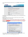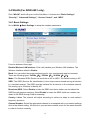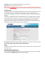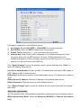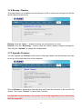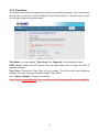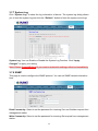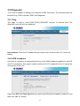
1
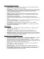
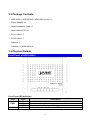
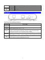
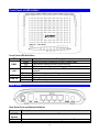
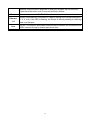
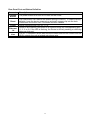
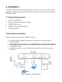
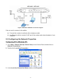
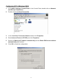
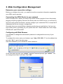
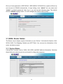
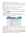
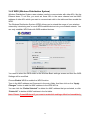
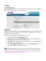
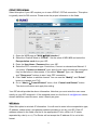
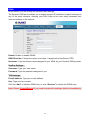
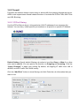
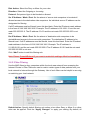
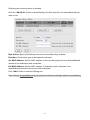
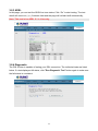
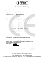
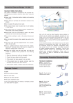
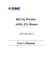
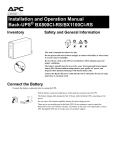
Wired / Wireless ADSL 2/2+ Router ADE-3400v3 / ADE-4400v3 / ADW-4401v4 User's Manual 1 Copyright Copyright© 2007 by PLANET Technology Corp. All rights reserved. No part of this publication may be reproduced, transmitted, transcribed, stored in a retrieval system, or translated into any language or computer language, in any form or by any means, electronic, mechanical, magnetic, optical, chemical, manual or otherwise, without the prior written permission of PLANET. PLANET makes no representations or warranties, either expressed or implied, with respect to the contents hereof and specifically disclaims any warranties, merchantability or fitness for any particular purpose. Any software described in this manual is sold or licensed "as is". Should the programs prove defective following their purchase, the buyer (and not this company, its distributor, or its dealer) assumes the entire cost of all necessary servicing, repair, and any incidental or consequential damages resulting from any defect in the software. Further, this company reserves the right to revise this publication and to make changes from time to time in the contents hereof without obligation to notify any person of such revision or changes. All brand and product names mentioned in this manual are trademarks and/or registered trademarks of their respective holders. Federal Communication Commission Interference Statement This equipment has been tested and found to comply with the limits for a Class B digital device, pursuant to Part 15 of FCC Rules. These limits are designed to provide reasonable protection against harmful interference in a residential installation. This equipment generates, uses, and can radiate radio frequency energy and, if not installed and used in accordance with the instructions, may cause harmful interference to radio communications. However, there is no guarantee that interference will not occur in a particular installation. If this equipment does cause harmful interference to radio or television reception, which can be determined by turning the equipment off and on, the user is encouraged to try to correct the interference by one or more of the following measures: 1. Reorient or relocate the receiving antenna. 2. Increase the separation between the equipment and receiver. 3. Connect the equipment into an outlet on a circuit different from that to which the receiver is connected. 4. Consult the dealer or an experienced radio technician for help. FCC Caution To assure continued compliance (example-use only shielded interface cables when connecting to computer or peripheral devices). Any changes or modifications not expressly approved by the party responsible for compliance could void the user’s authority to operate the equipment. This device complies with Part 15 of the FCC Rules. Operation is subject to the Following two conditions: (1) This device may not cause harmful interference, and (2) this Device must accept any interference received, including interference that may cause undesired operation. 2 Federal Communication Commission (FCC) Radiation Exposure Statement This equipment complies with FCC radiation exposure set forth for an uncontrolled environment. In order to avoid the possibility of exceeding the FCC radio frequency exposure limits, human proximity to the antenna shall not be less than 20 cm (8 inches) during normal operation. R&TTE Compliance Statement This equipment complies with all the requirements of DIRECTIVE 1999/5/EC OF THE EUROPEAN PARLIAMENT AND THE COUNCIL OF 9 March 1999 on radio equipment and telecommunication terminal Equipment and the mutual recognition of their conformity (R&TTE) The R&TTE Directive repeals and replaces in the directive 98/13/EEC (Telecommunications Terminal Equipment and Satellite Earth Station Equipment) As of April 8, 2000. WEEE Regulation To avoid the potential effects on the environment and human health as a result of the presence of hazardous substances in electrical and electronic equipment, end users of electrical and electronic equipment should understand the meaning of the crossed-out wheeled bin symbol. Do not dispose of WEEE as unsorted municipal waste and have to collect such WEEE separately. Safety This equipment is designed with the utmost care for the safety of those who install and use it. However, special attention must be paid to the dangers of electric shock and static electricity when working with electrical equipment. All guidelines of this and of the computer manufacture must therefore be allowed at all times to ensure the safe use of the equipment. Revision User’s Manual for Wired / Wireless ADSL 2/2+ Router Model: ADE-3400v3 / ADE-4400v3 / ADW-4401v4 Rev: 1.0 (Nov. 2007) Part No. EM-ADE3400v3_v1 3 Table of Contents 1. INTRODUCTION ........................................................................................................................................... 6 1.1 Feature ................................................................................................................................ 6 1.2 Package Contents .............................................................................................................. 8 1.3 Physical Details .................................................................................................................. 8 2. INSTALLATION .......................................................................................................................................... 14 2.1 System Requirement........................................................................................................ 14 2.2 Hardware Installation ....................................................................................................... 14 2.3 Configuring the Network Properties............................................................................... 15 3. WEB CONFIGURATION MANAGEMENT.................................................................................................. 19 3.1 ADSL Router Status ......................................................................................................... 20 3.1.1 System Status ........................................................................................................................ 20 3.1.2 LAN Status.............................................................................................................................. 21 3.1.3 WLAN Status (ADW-4401 only)............................................................................................. 21 3.1.4 WAN Status............................................................................................................................. 22 3.1.5 Port Mapping .......................................................................................................................... 22 3.1.6 Statistic ................................................................................................................................... 23 3.1.7 ARP Table ............................................................................................................................... 24 3.2 Wizard................................................................................................................................ 25 3.3 LAN .................................................................................................................................... 28 3.3.1 LAN Interface Settings........................................................................................................... 28 3.3.2 DHCP Server Settings............................................................................................................ 28 3.4 WLAN (For ADW-4401 only) ............................................................................................ 30 3.4.1 Basic Settings ........................................................................................................................ 30 3.4.2 Security ................................................................................................................................... 31 3.4.3 Advance Setting ..................................................................................................................... 33 3.4.4 Wireless Access Control ....................................................................................................... 34 3.4.5 WDS (Wireless Distribution System) ................................................................................... 35 3.5 WAN ................................................................................................................................... 36 3.5.1 WAN Interface......................................................................................................................... 36 3.5.2 ATM Settings .......................................................................................................................... 39 3.5.3 ADSL Settings ........................................................................................................................ 40 3.6 Advance ............................................................................................................................ 41 3.6.1 DNS.......................................................................................................................................... 41 4 3.6.2 Firewall .................................................................................................................................... 43 3.6.2.1 IP/Port filtering ............................................................................................................. 43 3.6.2.2 Mac Filtering................................................................................................................. 44 3.6.2.3 URL Block..................................................................................................................... 46 3.6.3 Virtual Server.......................................................................................................................... 47 3.6.3.1 Services ........................................................................................................................ 47 3.6.3.2 DMZ ............................................................................................................................... 48 3.6.4 Routing.................................................................................................................................... 49 3.6.4.1 RIP ................................................................................................................................. 49 3.6.4.2 Static Route .................................................................................................................. 50 3.6.5 IP QoS...................................................................................................................................... 51 3.6.6 Anti-DoS .................................................................................................................................. 52 3.6.7 Port Mapping .......................................................................................................................... 53 3.6.8 Other........................................................................................................................................ 54 3.6.8.1 IGMP Proxy................................................................................................................... 54 3.6.8.2 UPnP ............................................................................................................................. 54 3.6.8.3 Bridge............................................................................................................................ 55 3.7 Admin ................................................................................................................................ 56 3.7.1 Remote Access ...................................................................................................................... 56 3.7.2 Commit / Reboot .................................................................................................................... 56 3.7.3 Password ................................................................................................................................ 57 3.7.4 Backup / Restore.................................................................................................................... 58 3.7.5 Upgrade Firmware.................................................................................................................. 58 3.7.6 Time Zone ............................................................................................................................... 59 3.7.7 System Log............................................................................................................................. 60 3.7.8 SNMP ....................................................................................................................................... 60 3.7.9 TR-069 (ADW-4401 only)........................................................................................................ 61 3.7.10 ACL ........................................................................................................................................ 61 3.8 Diagnostic ......................................................................................................................... 63 3.8.1 Ping.......................................................................................................................................... 63 3.8.2 ATM Loopback ....................................................................................................................... 63 3.8.3 ADSL........................................................................................................................................ 64 3.8.4 Diagnostic............................................................................................................................... 64 APPENDIX A: GLOSSARY ............................................................................................................................ 65 5 1. Introduction The PLANET Wired / Wireless ADSL 2/2+ Router, the ADE-3400v3 / ADE-4400v3 / ADW-4401v4, provides office and residential users the ideal solution for sharing a High-Speed ADSL 2/2+ broadband Internet connection on the 10/100Mbps Fast Ethernet Interface and the 54Mbps wireless network. It can support downstream transmission rates up to 24Mbps and upstream transmission rates up to 3.5Mbps. The product supports PPPoA (RFC 2364 - PPP over ATM Adaptation Layer 5), PPP over Ethernet (RFC 2516), and RFC 1483 encapsulation over ATM (MER, bridged or routed) to establish a connection with ISP. Via the user-friendly management interface, the ADE-3400v3 / ADE-4400v3 / ADW-4401v4 can be managed by workstations running standard web browsers. Furthermore, the device provides DHCP server, NAT, Virtual Server, DMZ, access control, IP filter, VPN Pass-Through, and UPnP capability. The device also serves as an Internet firewall, protecting your network from being accessed by outside users. It provides the natural firewall function (Network Address Translation, NAT). All incoming and outgoing IPs are monitored and filtered by this product. In addition, it can be configured to block internal users from accessing to the Internet. 1.1 Feature Internet Access Features Shared Internet Access All users on the LAN or WLAN can access the Internet through the ADE-3400v3 / ADE-4400v3 / ADW-4401v4 using only a single external IP Address. The local (invalid) IP Addresses are hidden from external sources. This process is called NAT (Network Address Translation). Built-in ADSL 2/2+ Modem The device provides ADSL 2/2+ modem, and supports all common ADSL connections. PPPoE, PPPoA, Direct Connection Support Various WAN connections are supported by ADE-3400v3 / ADE-4400v3 / ADW-4401v4. Auto-detection of Internet Connection Method In most situations, the device can test your ADSL and Internet connection to determine the connection method used by your ISP. Fixed or Dynamic IP Address On the Internet (WAN port) connection, the device supports both Dynamic IP Address (IP Address is allocated on connection) and Fixed IP Address. 6 Advanced Internet Functions Virtual Servers This feature allows Internet users to access Internet servers on your LAN. The required setup is quick and easy. DMZ Support The device can translate public IP addresses to private IP address to allow unrestricted 2-way communication with Servers or individual users on the Internet. This provides the most flexibility to run programs, which could be incompatible in NAT environment. Firewall Supports simple firewall with NAT technology and provides option for blocking access from Internet, like Web, FTP, Telnet, SNMP, and ICMP. It also supports MAC and IP filtering. Universal Plug and Play (UPnP) UPnP allows automatic discovery and configuration of the Broadband Router. UPnP is supported by Windows ME, XP, or later. VPN Pass through Support PCs with VPN (Virtual Private Networking) software are transparently supported - no configuration is required. RIP1/2 Routing It supports RIPv1/2 routing protocol for routing capability. Simple Network Management Protocol (SNMP) It is an easy way to remotely manage the router via SNMP. LAN Features Ethernet Port The ADE-3400v3 provides one Ethernet port, making it easy to create or extend your LAN. 4-Port Switch The ADE-4400v3 / ADW-4401v4 incorporates a 4-Port 10/100Base-TX switching hub, making it easy to create or extend your LAN. DHCP Server Support Dynamic Host Configuration Protocol provides a dynamic IP address to PCs and other devices upon request. The device can act as a DHCP Server for devices on your local LAN and WLAN. Wireless Features (ADW-4401v4 only) Standards Compliant The ADW-4401v4 complies with the IEEE 802.11g (DSSS) specifications for Wireless LANs. Maximum of 54Mbps are supported. Supports both 802.11b and 802.11g Wireless Stations The 802.11g standard provides for backward compatibility with the 802.11b standard, so both 802.11b and 802.11g Wireless stations can be used simultaneously. WEP support Supports for WEP (Wired Equivalent Privacy) is included. Key sizes of 64 Bit and 128 Bit are supported. WPA-PSK support WPA_TKIP and WPA2_AES encryption are supported. Wireless MAC Access Control The Wireless Access Control feature can check the MAC address (hardware address) of Wireless stations to ensure that only trusted Wireless Stations can access your LAN 7 1.2 Package Contents ‧ ADE-3400v3 / ADE-4400v3 / ADW-4401v4 Unit x 1 ‧ Power Adapter x 1 ‧ Quick Installation Guide x 1 ‧ User’s Manual CD x 1 ‧ RJ-11 cable x 2 ‧ RJ-45 cable x 1 ‧ Splitter x 1 ‧ Antenna x 1 (ADW-4401v4) 1.3 Physical Details Front Panel of ADE-3400v3 Front Panel LED definition LED PWR Link State ON Red OFF ON Description When the router is powered on and in ready state. The devise is being turned on and booting. When the router is powered off. Successful connection between ADSL modem and telecom's 8 Flashing Flashing ON Flashing Data LAN network. Modem is trying to establish a connection to telecom’s network. Data is transferred between Router and Internet. Link TX or RX activity. Rear Panel Rear Panel Port and Button Definition Connector POWER Button Description The power button is for turn on or turns off the router. Power Power connector with 10V DC 1.0 A Reset The reset button can restore the default settings of device. To restore factory defaults, keep the device powered on and push a paper clip into the hole. Press down the button over 5 seconds and then release. Ethernet Router is successfully connected to a device through the Ethernet port. If the LED is flashing, the Router is actively sending or receiving data over that port. Line The RJ-11 connector allows data communication between the modem and the ADSL network through a twisted-pair phone wire. 9 Front Panel of ADE-4400v3 Front Panel LED definition LED PWR State Green Red OFF ON Link Data LAN 1-4 Flashing Flashing ON Flashing Description When the router is powered on and in ready state. The devise is being turned on and booting. When the router is powered off. Successful connection between ADSL modem and telecom's network. Modem is trying to establish a connection to telecom’s network. Data is transferred between Router and Internet. Link TX or RX activity Rear Panel Rear Panel Port and Button Definition Connector Description POWER Button Reset The power button is for turn on or turns off the router. The reset button can restore the default settings of device. To restore factory 10 defaults, keep the device powered on and push a paper clip into the hole. Press down the button over 5 seconds and then release. Power Power connector with 12V DC 1.5 A Ethernet 1-4 Router is successfully connected to a device through the corresponding port (1, 2, 3, or 4). If the LED is flashing, the Router is actively sending or receiving data over that port. Line The RJ-11 connector allows data communication between the modem and the ADSL network through a twisted-pair phone wire. 11 Front Panel of ADW-4401v4 Front Panel LED definition LED PWR State Green Red OFF ON Link WLAN LAN 1-4 Flashing ON Flashing OFF ON Flashing Description When the router is powered on and in ready state The devise is being turned on and booting When the router is powered off Successful connection between ADSL modem and telecom's network Modem is trying to establish a connection to telecom’s network The Wireless Interface is ready The Wireless data is transmitting The Wireless Interface is disable Link TX or RX activity Rear Panel 12 Rear Panel Port and Button Definition Connector Description The power button is for turn on or turns off the router. POWER Button The reset button can restore the default settings of device. To restore factory Reset defaults, keep the device powered on and push a paper clip into the hole. Press down the button over 5 seconds and then release. Power connector with 12V DC 1.5 A Power Router is successfully connected to a device through the corresponding port Ethernet (1, 2, 3, or 4). If the LED is flashing, the Router is actively sending or receiving 1-4 data over that port. The RJ-11 connector allows data communication between the modem and the Line ADSL network through a twisted-pair phone wire. 13 2. Installation This chapter offers information about installing your router. If you are not familiar with the hardware or software parameters presented here, please consult your service provider for the values needed. 2.1 System Requirement 1. Personal computer (PC) 2. Pentium III 266 MHz processor or higher 3. 128 MB RAM minimum 4. 20 MB of free disk space minimum 5. RJ45 Ethernet Port 2.2 Hardware Installation Please connect the device to you computer as follow: z If connecting to the splitter, connect the “Line” splitter to wall jack using one telephone cable z Use another telephone cable to connect “MODEM” port of the splitter and “LINE” port of the modem. The “Phone” port of the splitter can be use to connect the telephone by a telephone cable. z Use Ethernet cable to connect “LAN” port of the modem and “LAN” port of your computer. Figure 1 ADE-3400 connection diagram 14 Figure 2 ADE-4400 / ADW-4401 connection diagram If do not need to connect to the splitter, z Connect the modem to wall jack with a telephone cable. z Use Ethernet cable to connect “LAN” port of the modem and network adaptor of your computer. 2.3 Configuring the Network Properties Configuring PC in Windows XP 1. Go to Start / Control Panel (in Classic View). In the Control Panel, double-click on Network Connections 2. Double-click Local Area Connection. 3. In the Local Area Connection Status window, click Properties. 15 4. Select Internet Protocol (TCP/IP) and click Properties. 5. Select the Obtain an IP address automatically and the Obtain DNS server address automatically radio buttons. 6. Click OK to finish the configuration. 16 Configuring PC in Windows 2000 1. 2. Go to Start / Settings / Control Panel. In the Control Panel, double-click on Network and Dial-up Connections. Double-click Local Area Connection. 3. In the Local Area Connection Status window click Properties. 4. Select Internet Protocol (TCP/IP) and click Properties. 5. Select the Obtain an IP address automatically and the Obtain DNS server address automatically radio buttons. Click OK to finish the configuration. 6. 17 Configuring PC in Windows 98/Me 1. Go to Start / Settings / Control Panel. In the Control Panel, double-click on Network and choose the Configuration tab. 2. Select TCP/IP Æ NE2000 Compatible, or the name of your Network Interface Card (NIC) in your PC. 3. Select the Obtain an IP address automatically radio button. 4. Then select the DNS Configuration tab. 5. Select the Disable DNS radio button and click OK to finish the configuration. 18 3. Web Configuration Management Determine your connection settings Before you configure the router, you need to know the connection information supplied by your ADSL service provider. Connecting the ADSL Router to your network Unlike a simple hub or switch, the setup of the ADSL Router consists of more than simply plugging everything together. Because the Router acts as a DHCP server, you will have to set some values within the Router, and also configure your networked PCs to accept the IP Addresses the Router chooses to assign them. Generally there are several different operating modes for your applications. And you can know which mode is necessary for your system from ISP. These modes are router, bridge, PPPoE+NAT, and PPPoA+NAT. Configuring with Web Browser It is advisable to change the administrator password to safeguard the security of your network. To configure the router, open your browser, type “http: //192.168.1.1” into the address bar and click “Go” to get to the login page. Save this address in your Favorites for future reference. At the User name prompt, type “admin”. And the Password prompt, type “admin”. You can change these later if you wish. Click “OK”. 19 Once you have powered on ADE-3400v3 / ADE-4400v3 / ADW-4401v4, system will boot up and connect to DSLAM automatically. In login dialog, enter “admin” as user name and “admin” as default password. After log in, you will see the following page. The default screen is Wizard setting screen. You can configure the device step by step. 3.1 ADSL Router Status The Status screen display system information of your Router. It includes the System, LAN, WLAN, WAN, Port Mapping, Statistic and ART Table. You can see the information of the router via these screens. 3.1.1 System Status It shows the Firmware Version, WAN, LAN, ADSL, and MAC address information. Note that these fields are read-only and are not meant for diagnostic purposes. 20 3.1.2 LAN Status You can see the LAN IP address, Mask, DHCP status, MAC and DHCP Client Table in this screen. 3.1.3 WLAN Status (ADW-4401 only) You can see the basic settings and status of wireless Interface in this screen. It includes the wireless band, mode, SSID and client list etc. 21 3.1.4 WAN Status You can see the VPI/VCI, Encapsulation type, Protocol, WAN IP address, Gateway and DNS information in this screen. 3.1.5 Port Mapping You can see the Port Mapping information in this screen. It includes the status and Mapping Relation. 22 3.1.6 Statistic You can see the Statistic information in this screen. It includes the Traffic and DSL statistic. Traffic Statistic Screen The screen shows the statistic of LAN, WLAN and WAN Port. Click the Refresh button to refresh the information. DSL Statistic The screen shows the ADSL line statistic. 23 3.1.7 ARP Table You can see the ARP information in this screen. Click the Refresh button to refresh the information. 24 3.2 Wizard You can use "Wizard" to setup the router as follows, and the router will connect to the Internet via ADSL line. Step 1. Click "Wizard" to get into the quick setup procedures. It will show the below screen. Enter the VPI / VCI value that provided by your ISP. Step 2. Click "Next" to setup your Internet connection type. You can have this information from your Internet Service Provider. 25 Step 3. Select the WAN IP type; select the WAN IP setting provided by your ISP. Step 4. Enter the user name and password that your ISP has provided to you. Select the connection type that you want to use. There are three types for your selection – Continuous, Connect on Demand and Manual. 26 Step 5. Click "Next" to setup your LAN IP and DHCP Server setting. Step 6. Enter the Finish to save settings and reboot the device or click Back to modify your settings. 27 3.3 LAN The LAN setup includes two parts – LAN Interface and DHCP Settings. 3.3.1 LAN Interface Settings There are the IP settings of the LAN Interface for the device. These settings may be referred to as Private settings. You may change the LAN IP address if needed. The LAN IP address is provided to your internal network and cannot be seen on the Internet. You can change the LAN IP address for your requirements. The default LAN IP is 192.168.1.1. You can also enable the Secondary LAN IP function in this page. It will allow LAN Interface to have the alias IP for management. IP Address: Enter the IP address of your ADSL router in dotted decimal notation, for example, 192.168.1.1 (default setting). IP Subnet Mask: Your ADSL router will automatically calculate the subnet mask based on the IP address that you assign. Unless you are implementing sub netting, use the subnet mask computed by the ADSL router. Note: Please Commit/Reboot if you want to make this settings effective immediately 3.3.2 DHCP Server Settings Enable the DHCP Server if you are using this device as a DHCP server. This page lists the IP address pools available to hosts on your LAN. The device distributes numbers in the pool to hosts on your network as they request Internet access. You can setup DHCP server to assign IP address to your PC automatically. You can also manually assign an IP according to the MAC address of PC’s network card. The ADSL 28 Router supports DHCP Relay and Server mode, or select Disable to disable the DHCP Server. IP Pool Range: Enter the start IP and end IP address you wish to use as the DHCP server's IP assignment. Max Lease Time: Enter the amount of time you wish to lease out a given IP address. Domain Name: Enter your domain name. Gateway Address: Enter the default gateway IP address. Default is the LAN IP address. Note: Please Commit/Reboot if you want to make this settings effective immediately MAC-Base Assignment: Click this button will pop-up a new window to assign IP address according to MAC address. Enter the MAC address and the IP address that you wish to assign in the fields. Click the “Assign IP” button to add it in the MAC-Base Assignment Table. 29 3.4 WLAN (For ADW-4401 only) Click “WLAN” and it will open out the Sub-Menu. It includes the “Basic Settings”, “Security”, “Advanced Settings”, “Access Control”, and “WDS”. 3.4.1 Basic Settings Go to WLAN Æ Basic Settings to setup the wireless parameters. Function buttons in this page: Disable Wireless LAN Interface: Click it will disable your Wireless LAN Interface. The Wireless Interface default is Enable. Band: You can select the proper wireless type for your requirements and environment. There are following types: 2.4GHz(B)/ 2.4GHz(G)/ 2.4GHz(B+G). Mode: The Wireless ADSL Router can work like an AP or WDS. The Default setting is AP. SSID: The SSID (Service Set Identification) is the unique name shared among all devices in a wireless network. The SSID must be identical for all devices in the wireless network. Set a string up to 32 letters to identify AP. Broadcast SSID: Select Disable to hide the SSID such that a station can not obtain the SSID through passive scanning. Select Enable to make the SSID visible so a station can obtain in the SSID through Passive scanning. Country / Area: The channel will adjust according to nations to adapt to each nation's frequency provision. Channel Number: Select the appropriate channel to correspond with your network settings. Auto is the default setting. All devices in your wireless network must use the same channel in order to function correctly. 30 Send Rate: Select the Wireless Data Rate that you want to use. Radio Power: 10%, 25%, 50%, 80%, 100%. Note: Please Commit/Reboot if you want to make this settings effective immediately 3.4.2 Security This page allows you can configure security features of the wireless LAN interface. You can set the network authentication method, selecting data encryption, specify whether a network key is required to authenticate to this wireless network and specify the encryption strength. This device is equipped with 802.1X and WPA/WPA2 (Wi-Fi Protected Access), the latest security standard. It also supports the legacy security standard, WEP (Wired Equivalent Privacy). By default, wireless security is disabled and authentication is open. Before enabling the security, consider your network size, complexity, and existing authentication infrastructure and then determine which solution applies to it. Encryption: Select the Encryption mode for Authentication. There are five modes for select. None / WEP / WPA (TKAP)/ WPA2 (AES)/ WPA2 Mixed. None: The data is not encrypted when it is transferred from the device to the client station. This is the default option. WEP (Wired Equivalent Privacy): Encrypts data frames before transmitting over the wireless network. After you select WEP, you can click the “Set WEP Key” button for further settings. 31 Following is a description of the different options: 1. 2. 3. 4. Key Length: Select 64-bit WEP or 128-bit WEP to use data encryption. Key Format: Select the ASCII or Hex format for encryption. Default Tx Key: Select Key 1 ~ 4 for your default Encryption Key. Network Key 1 to 4: Enter 5 ASCII characters or 10 hexadecimal digits for 64-bit encryption keys to fill out WEP keys box. Or enter 13 ASCII characters or 26 hexadecimal digits for 128-bit encryption keys to fill out WEP keys box. The system allows you to type in 4 kinds of the WEP key. Click "Apply Changes" to save the wireless security options and then click “Close” to return the Security Setup screen. Use 802.1x Authentication: Enable the 802.1x Authentication and select WEP 64bits or WEP 128bits for 802.1x authentication. Radius Port: Enter the port number of the authentication server. The default port number is 1812. Radius Server IP Address: Enter the IP Address of the authentication server. Radius Password: Enter the same key as the Radius server’s. Click "Apply Changes" again to save the wireless security options and make the change take effect. WPA(TKIP) / WPA2(AES): Wi-Fi Protected Access, encrypts data frames before transmitting over the wireless network. WPA Authentication Mode: Select the Enterprise (RADIUS) or Personal (Pre-Shared Key). 32 Pre-shared Key Format: Select the Passphrase or Hax format. Pre-shared Key: Enter the pre-shared key for WPA. Client stations must use the same key in order to connect with this device. Check the table below for instructions when entering the key. Radius Port: Enter the port number of the authentication server. The default port number is 1812. Radius Server IP Address: Enter the IP Address of the authentication server. Radius Password: Enter the same key as the Radius server’s. Click "Apply Changes" again to save the wireless security options and make the change take effect. Note: Please Commit/Reboot if you want to make this settings effective immediately 3.4.3 Advance Setting These settings are only for more technically advanced users who have a sufficient knowledge about wireless LAN. These settings should not be changed unless you know what effect the changes will have on your Access Point. Fragment Threshold: The threshold (number of bytes) for the fragmentation boundary for directed messages. It is the maximum data fragment size that can be sent. Enter a value between 256 and 2346. RTS Threshold: The RTS (Request To Send) threshold (number of bytes) for enabling RTS/CTS handshake. Data with its frame size larger than this value will perform the RTS/CTS handshake. Set this attribute to be larger than the maximum MSDU (MAC Service Data Unit) size TURNS OFF the RTS/CTS handshake. Set this attribute to ZERO TURNS ON the RTS/CTS handshake. Enter a value between 0 and 2347. 33 Beacon Interval: The Beacon Interval value indicates the frequency interval of the beacon. Enter a value between 20 and 1024. A beacon is a packet broadcast by the Router to synchronize the wireless network. Note: Please Commit/Reboot if you want to make this settings effective immediately 3.4.4 Wireless Access Control You can allow or deny a lust of MAC addresses associated with the wireless stations access to the ADSL Router. Wireless Access Control Mode: Select the Disabled to disable this function. Select the Allow to make any wireless MAC address in the Wireless Access Control List can be linked to. And select the Deny to ban any wireless MAC address in the Wireless Access Control List to be linked to. Add MAC Access Control: To add a new MAC address to your wireless MAC address filters, type in the MAC Address in the entry field provided. And then click on the “Apply Changes” button to add the MAC address to the list. The MAC address will appear listed in the table below. You can click the “Delete” to delete the MAC address that you selected, or click “Delete All” to delete all MAC address in the list table. Note: Please Commit/Reboot if you want to make this settings effective immediately 34 3.4.5 WDS (Wireless Distribution System) Wireless Distribution System uses wireless media to communicate with other APs, like the Ethernet does. To do this, you must set these APs in the same channel and set MAC address of other APs which you want to communicate with in the table and then enable the WDS. The Wireless Distribution System (WDS) allows you to extend the range of your wireless network by introducing one or more WDS-enabled devices into your wireless network. You can only establish WDS links with WDS-enabled devices. You need to select the WDS mode in the Wireless Basic settings screen and then the WDS Settings will be modified. Choose Enable WDS to enable the WDS function. Type in the MAC address and Comment in the entry fields. And then click on the “Apply Changes” button to add the MAC address to the WDS AP list. You can click the “Delete Selected” to delete the MAC address that you selected, or click “Delete All” to delete all MAC address in the list table. Note: Please Commit/Reboot if you want to make this settings effective immediately 35 3.5 WAN 3.5.1 WAN Interface ADSL 2/2+ Router provide 8 PVCs with different channel mode. You can select the Bridge / MER / PPPoE / PPPoA mode for your environment. Bridge Mode The device can be configured to act as a bridging device between your LAN and your ISP. Bridges are devices that enable 2 or more networks to communicate as if they are 2 segments of the same physical LAN. ADSL 2/2+ Router is bridge mode enabled by factory default. 1. Open the WEB page in “WAN Æ WAN Interface”. 2. Select the Channel Mode to “1483 Bridged”. Set the parameters VPI / VCI and Encapsulation mode according to the ISP provided. 3. Click “Add” button to add this channel into VC table. You can use the “Modify” and “Delete” button to manage your PVC. 4. Go to “Admin Æ Commit/Reboot” menu, clink “Commit and Reboot” button. The device will reboot and apply this setting. “Commit and Reboot”: Whenever you use the web console to change system settings, the changes are initially placed in temporary storage. To save your changes for future use, you need to use the commit function. This function saves your changes from RAM to flash memory and then reboot the system. 36 PPPoE / PPPoA Mode Select this option if your ISP requires you to use a PPPoE / PPPoA connection. This option is typically used for DSL service. Please enter the proper information in the fields. 1. Open the WEB page at “WAN Æ WAN Interface”. 2. Select the Channel Mode to “PPPoE”. Set the value of VPI / VCI and select the Encapsulation mode from your ISP. 3. Enter the User Name / Password from your ISP. 4. Select the PPP connection type: Continuous, Connect on demand and Manual. If you select “Connect on demand” type, specify how many minutes the connection may be idle before it disconnects. If you select “Manual” type, use “Connect” and ”Disconnect” buttons to start / stop PPP connection. 5. Click “Add” button to add this channel. You can use the “Modify” and “Delete” button to manage your PVC. 6. Go to “Admin Æ Commit/Reboot” menu, clink “Commit and Reboot” button. The device will reboot and apply this setting. Your ISP should provide the above information. Note that you must enter the user name exactly as your ISP assigned it. If the assigned name is in the form of user@domain where domain identifies a service name, enter it exactly as given. MER Mode Select this option to set static IP information. You will need to enter in the encapsulation type, IP address, subnet mask, and gateway address provided to you by your ISP. Each IP address entered in the fields must be in the appropriate IP form, which is 4 IP octets separated by a dot (x.x.x.x). The Router will not accept the IP address if it is not in this format. 37 1. Open the WEB page at “WAN Æ WAN Interface”. 2. Select the Channel Mode to “1483 MER”. Set the value of VPI / VCI and select the Encapsulation mode from your ISP. 3. Select the WAN IP type: DHCP or Fixed IP. 4. Select Fixed IP to set static IP information. You will need to enter in the IP address, subnet mask, and gateway address provided to you by your ISP. Each IP address entered in the fields must be in the appropriate IP form, which are 4 IP octets separated by a dot (x.x.x.x). The Router will not accept the IP address if it is not in this format. 5. Select DHCP if your ISP provides you an IP address automatically. The router will obtain an IP address automatically. 6. Click “Add” button to add this channel. You can use the “Modify” and “Delete” button to manage your PVC. 7. Go to “Admin Æ Commit/Reboot” menu, clink “Commit and Reboot” button. The device will reboot and apply this setting 38 3.5.2 ATM Settings The page is for ATM PVCs’ QoS mode setting. The device supports 4 QoS mode — UBR / CBR /rt-VBR / nrt-VBR. You can click the “ATM Setting” on the WAN Interface setting screen. ATM QoS: Select the Quality of Service types for this Virtual Circuit. The ATM QoS types include CBR(Constant Bit Rate), VBR(Variable Bit Rate) and UBR (Unspecified Bit Rate). These QoS types are all controlled by the parameters specified below, including PCR, SCR, and MBS. CBR is for connections that support constant rates of data transfer. The only parameter you need to worry about in CBR is PCR. UBR is for connections that have variable traffic. The only parameter you need to worry about in UBR is PCR. rt-VBR is for connections that, while having variable traffic, require precise timing between traffic source and destination. PCR, SCR and MBS must all be set for rt-VBR. nrt-VBR is for connections that have variable traffic, do not require precise timing, but still require a set bandwidth availability. PCR, SCR and MBS must all be set for nrt-VBR. PCR: Peak Cell Rate (PCR) is the maximum rate at which the sender can send cells. This parameter may be lower (but not higher) than the maximum line speed. 1 ATM cell is 53 bytes (424 bits), so a maximum speed of 832 Kbps gives a maximum PCR of 1962 cells/sec. This rate is not guaranteed because it is dependent on the line speed. 39 SCR: Sustained Cell Rate (SCR) is the mean cell rate of a bursty, on-off traffic source that can be sent at the peak rate, and a parameter for burst-type traffic. SCR may not be greater than the PCR; the system default is 0 cells/sec. MBS: Maximum Burst Size (MBS) is the maximum number of cells that can be sent at the PCR. After MBS is reached, cell rates fall below SCR until cell rate averages to the SCR again. At this time, more cells (up to the MBS) can be sent at the PCR again. “Apply Changes”: Set new PVC QoS mode and values for the selected PVC. “Undo”: Discard your settings. 3.5.3 ADSL Settings You can set ADSL connect mode here. It supports G.Lite, G.Dmt, T1.413, ADSL2 and ADSL2+. You can also set Annex L, M Option, ADSL Capability and ADSL Tone Mask in this page. 40 3.6 Advance You can configure different advanced services in this part. It includes DNS, Firewall, Virtual Server, Routing, IP QoS, Anti-DoS, Port Mapping and Other. 3.6.1 DNS In this screen, you can modify the DNS server settings. It includes the DNS and DDNS functions. DNS Configuration Attain DNS Automatically: If “Attain DNS Automatically” checkbox is selected, this router will accept the first received DNS assignment from one of the PPPoA, PPPoE or MER/DHCP enabled PVC(s) during the connection establishment. Set DNS Manually: Select this method; you need to enter the DNS Server IP address manually. You can enter three entries in these fields. 41 DDNS In this screen, you can modify the Dynamic DNS settings. The Dynamic DNS service allows you to alias a dynamic IP address to a static hostname in any of the many domains, allowing your DSL router to be more easily accessed from various locations on the Internet. Enable: Enable or disable DDNS. DDNS Provider: Choose the option of provider. It supports the DynDns and TZO. Hostname: Type the domain name assigned to your ADSL by your Dynamic DNS provider. DynDns Settings: Username: Type your user name. Password: Type the password assigned to you. TZO Settings: E-mail Address: Type your e-mail address. Key: Type your key number. Click the “Add” to add this DDNS entry or click “Remove” to delete the DDNS entry. Note: Please Commit/Reboot if you want to make this settings effective immediately 42 3.6.2 Firewall Firewall is an advance feature used to deny or allow traffic from passing through the device. ADSL router support some firewall related functions. It includes the IP/Port Filter, MAC Filter and URL Blocking. 3.6.2.1 IP/Port filtering Use the IP/Port filters to deny / allow particular LAN IP addresses from accessing the Internet. You can deny / allow specific port numbers or all ports for a specific IP address. Default Setting: Specify default filtering rule action to be either Deny or Allow if no other rules can be applied. You can specify the direction on Outgoing and Incoming. Click the “Apply Changes” to apply your setting. By default, all outgoing IP traffic from LAN is allowed, and all IP traffic from WAN is deny. Click the “Add Rule” button to show filtering rule field, Enter the rule information that you want to use. 43 Rule Action: Select the Deny or Allow for your rules. Direction: Select the Outgoing or Incoming. Protocol: Set protocol type to be blocked or allowed. Src IP Address / Mask / Port: Set the subnet of source side computers to be denied / allowed access to the destination side computers. An individual source IP address can be designated for filtering. If all IP addresses must be filtered, leave this box blank. Enter the IP/subnet mask address in the form of XXX.XXX.XXX.XXX. Example: The IP address is 192.168.1.21 and the net mask 255.255.255.0. The IP address 0.0.0.0 and the net mask 255.255.255.255 is not care. Dst IP Address / Mask / Port: Set the subnet of destination side computers to be denied/allowed access to the source side computers. The destination IP address to be filtered is set. If all IP addresses must be filtered, leave this box blank. Enter the IP/subnet mask address in the form of XXX.XXX.XXX.XXX. Example: The IP address is 211.95.68.121 and the net mask 255.255.255.0.The IP address 0.0.0.0 and the net mask 255.255.255.255 is not care. Click “Add” button to add this filtering rule. Note: Please Commit/Reboot if you want to make this settings effective immediately 3.6.2.2 Mac Filtering Use the MAC filters to deny computers within the local area network from accessing the Internet. Entries in Filter Table are used to restrict certain types of data packets from your local network to Internet through the Gateway. Use of such filters can be helpful in securing or restricting your local network. Default Action: Specify default filtering rule action to be either Deny or Allow if no other rules can be applied. Click the “Apply Changes” to apply your setting. By default, all 44 Outgoing and Incoming action is allowed. Click the “Add Rule” button to show filtering rule field, enter the rule information that you want to use. Rule Action: Specify this filtering rule action to be either Deny or Allow. Direction: Set direction type to be blocked or allowed. Src MAC Address: Set the MAC address of source side computers to be denied/allowed access to the destination side computers. Dst MAC Address: Set the MAC address of destination side computers to be denied/allowed access to the source side computers. Click “Add” button to add this filtering rule. Note: Please Commit/Reboot if you want to make this settings effective immediately 45 3.6.2.3 URL Block This page is used to configure the Blocked FQDN (Such as tw.yahoo.com) and filtered keyword. Here you can add / delete FQDN and filtered keyword. URL Blocking: Enable or Disable URL Blocking. Click the “Apply Changes” to apply your setting. URL Blocking: Enter the FQDN in the field and click the “Add FQDN” button to add this rule. Keyword Filtering: Enter the keyword which you want to block. Click “Add keyword” button to add this filtering rule. Note: Please Commit/Reboot if you want to make this settings effective immediately 46 3.6.3 Virtual Server The Virtual Server is the server or server(s) behind NAT (on the LAN), for example, Web server or FTP server, that you can make visible to the outside world even though NAT makes your whole inside network appear as a single machine to the outside world. The Virtual Server includes two parts – Services and DMZ. 3.6.3.1 Services Click “Add” to show the Virtual Server setting screen. Service Type: Select one service item, such as Mail (SMTP), Mail (POP3), Web Server (HTTP), FTP Server, and DNS, from the list. The information about the selected item will appear in the box below. Customized services: Enter a new service name to establish a specified user service category. Protocol: Choose proper protocols for your services. WAN Port start / end: When you have already selected one service, the port number will appear automatically. You can change it as you need. Server Host Port: When you have already selected one service, the port number will appear automatically. You can change it as you need. Server IP Address: When you intend to assign a specified address to the virtual server, enter the server IP address here. Click “OK” button to add this Virtual Server entry. Note: Please Commit/Reboot if you want to make this settings effective immediately 47 3.6.3.2 DMZ A DMZ (Demilitarized Zone) allows a single computer on your LAN to expose ALL of its ports to the Internet. Enter the IP address of that computer as a DMZ (Demilitarized Zone) host with unrestricted Internet access. When doing this, the DMZ host is no longer behind the firewall. Enable DMZ: Click it to enable the DMZ function. Enter “DMZ Host IP Address” and click “Apply Changes” to activate the DMZ host. Note: Please Commit/Reboot if you want to make this settings effective immediately 48 3.6.4 Routing You have two ways to manage the device’s routing information. It includes RIP and Static Route. 3.6.4.1 RIP Enable the RIP if you are using this device as a RIP-enabled router to communicate with others using the Routing Information Protocol. This page is used to select the interfaces on your devices that use RIP, and the version of the protocol used. To activate RIP for the device, select the “Enabled” radio button for RIP Mode and click “Apply Changes” to apply it. To configure an individual interface, select the Interface, desired RIP version and Send mode. Click the “Add” button to save the configuration, and to start or stop RIP based on the Global RIP mode selected. 49 3.6.4.2 Static Route This page is used to configure the routing information. Here you can add / delete IP routes. Click “Enable” to enable the Static Routing function, you can query the preset static routes, delete an existing static route, or add a new static route. By default, the system has no static route information. Destination: The IP address where packets will go to. Subnet Mask: The subnet mask of the destination IP address. Next Hop: The gateway that the packets will pass by during transmission. Metric: Metric represents the “cost” of transmission for routing purposes. IP Routing uses hop count as the measurement of cost, with a minimum of 1 for directly connected networks. Enter a number that approximates the cost for this link. The number need not to be precise, but it must between 1 and 15. In practice, 2 or 3 is usually a good number. Interface: The interface that the packets pass through on the device. Click “Add Route” to add this routing information. 50 3.6.5 IP QoS Entries in this table are used to assign the precedence for each incoming packet based on physical LAN port, TCP / UDP port number, and source / destination IP address / subnet masks. IP QoS: Enable or Disable IP QoS function. Click the “Apply Changes” to apply your setting. When you click “Add Rule” button, the IP QoS Setting screen will appear. You can specify the network Outbound Priority on this setting. 51 3.6.6 Anti-DoS "denial-of-service attack" (DoS Attack), a type of attack on a network that is designed to bring the network to its knees by flooding it with useless traffic. This page is used to prevent DOS attacks that you configure. Select “Enable” can automatically detect and block Denial of Service (DoS) attacks, such as Ping of Death, SYN Flood, Port Scan and Land Attack. Select the attack types that you want to block and click “Apply Changes” to apply your settings. Note: Please Commit/Reboot if you want to make this settings effective immediately 52 3.6.7 Port Mapping Port Mapping supports multiple ports to PVC and bridging groups. Each group will perform as an independent network. To support this feature, you must create mapping groups with appropriate LAN and WAN interfaces using the Add button. The Delete button will remove the grouping and add the ungrouped interfaces to the Default group. To manipulate a mapping group: 1. Select a group from the table. 2. Select interfaces from the WAN and LAN interface list and add them to the grouped interface list using the arrow buttons to manipulate the required mapping of the ports. 3. Click "Apply Changes" button to save the changes. Note: 1. An interface only belongs to one group. 2. Please Commit/Reboot if you want to make this settings effective immediately. 53 3.6.8 Other This function includes as following parts – IGMP Proxy, UPnP and Bridge. 3.6.8.1 IGMP Proxy IGMP Proxy enables the system to issue IGMP host messages on behalf of hosts that the system discovered through standard IGMP interfaces. The system acts as a proxy for its hosts when you enable it by doing the follows: Enable IGMP proxy on WAN interface (upstream), which connects to a router running IGMP. .Enable IGMP on LAN interface (downstream), which connects to its hosts. Note: Please Commit/Reboot if you want to make this settings effective immediately 3.6.8.2 UPnP UPnP (Universal Plug and Play) is a distributed, open networking standard that uses TCP/IP for simple peer-to-peer network connectivity between devices. An UPnP device can dynamically join a network, obtain an IP address, convey its capabilities and learn about other devices on the network. In turn, a device can leave a network smoothly an automatically when it is no longer in use. UPnP broadcasts are only allowed on the LAN. How do I know if I'm using UPnP? UPnP hardware is identified as an icon in the Network Connections folder (in Windows XP & Windows ME). Each UPnP-compatible device that is installed on your network will appear as a separate icon. 54 Click “Enable” to enable UPnP function and select the WAN Interface. Click “Apply Changes” to apply your setting. Note: Please Commit/Reboot if you want to make this settings effective immediately 3.6.8.3 Bridge This page is used to configure the bridge parameters. Here you can change the settings or view some information on the bridge and its attached ports. Aging Time: Enter the time for the bridge. 802.1d Spanning Tree: You can Enable or Disable the 802.1d Spanning Tree Protocol. Click “Apply Changes” to apply your setting. Note: Please Commit/Reboot if you want to make this settings effective immediately 55 3.7 Admin You can configure admin management in this part. It includes Remote Access, Commit / Reboot, Password, Backup / Restore, Update Firmware, Time Zone, System Log, SNMP TR-069 (For ADW-4401), and ACL. 3.7.1 Remote Access User can enable or disable remote management services for the LAN and WAN. Select the service items which you want to remote management. Click “Apply Changes” to apply your setting. 3.7.2 Commit / Reboot The Comit / Reboot screen allows you to restart your router with its current settings or the factory default settings. 56 If you want reset the current settings to factory default, please choose "reset to default settings", and then press "Reboot" to reboot system. If you want commit current settings, please choose "commit current settings", and then press "Reboot" to reboot system. 3.7.3 Password This page is used to set the account to access the web server of ADSL Router.The new password will be availability after system reboot. User Name: There are two level user accounts for your selection. The admin account have full rights for device management, and the user account only can see the status information of this device. Old Password: Enter the old password. New Password: Enter your new password. Confirmed Password: Enter your new password again. Click “Apply Changes” to apply your setting. 57 3.7.4 Backup / Restore This page allows you to backup current settings to a file or restore the settings from the file which was saved previously. Backup: Click the “Save…” button to backup the configuration of router. Restore: Click the “Browsing...” button, select the correct update configure settings file. Then click the “Upload” to update the configurations. 3.7.5 Upgrade Firmware You can upgrade the firmware of the router in this page. Make sure the firmware you want to use is on the local hard drive of the computer. Click on Browse to browse the local had drive and locate the firmware to be used for the update. Then press “Upload” to upload new Firmware. It might take several minutes, don’t power off it during upgrading. Device will restart after the upgrade!! 58 3.7.6 Time Zone The system time is the time used by the device for scheduling services. You can manually set the time or connect to a NTP (Network Time Protocol) server. If an NTP server is set, you will only need to set the time zone. Time Mode: You can choose “Time Server” or “Manually” to coordinate the time. SNTP Server: Select the NTP Server from the slide down menu or enter the NTP IP address manually. Time Zone: Choose the Time Zone of your location. This will set the time difference between your time zone and Greenwich Mean Time (GMT). Click “Apply Changes” to apply your setting. Note: Please Commit/Reboot if you want to make this settings effective immediately 59 3.7.7 System Log Click “System Log” to show the log information of device. The system log dialog allows you to view the system log and click the “Refresh” button to fresh the system event logs. System Log: You can Enable or Disable the System Log Function. Click “Apply Changes” to apply your setting. Note: Please Commit/Reboot if you want to make this settings effective immediately 3.7.8 SNMP This page is used to configure the SNMP protocol. You can set SNMP related information here. Read Community: Select to set the password for incoming Get- and GetNext request from management station. Write Community: Select to set the password for incoming Set request from management station. 60 The default password is “public”. When you are done making changes, click “Apply Changes” to apply your setting. 3.7.9 TR-069 (ADW-4401 only) This page is used to configure the TR-069 CPE. Here you may change the setting for the ACS's parameters. 3.7.10 ACL Access Control List Configuration If enabled, permits access to local management services from IP addresses contained in the Access Control List. If enable ACL, and then only the effective IP in ACL can access the router. 61 Step1 If you want to enable ACL, please choose "Enable" and then press "Apply Changes" to apply your setting. Step2 Click the Enable checkbox. Step3 Enter the host IP address that you want to permit and click “Add”. Step4 Press "take effect" to enable the configuration. Note: If you choose "Enable" in ACL Capability, please make sure that your host IP is in ACL before it takes effect. Or you will not manage the device from your PC. 62 3.8 Diagnostic Your router is capable of testing your network and DSL connection. The individual tests are listed as Ping, ATM Loopback, ADSL and Diagnostic. 3.8.1 Ping This page is used to send ICMP ECHO_REQUEST packets to network host. The diagnostic result will then be displayed. Host Address: Enter the IP address that you wish to test. And then click “Go” button for testing. 3.8.2 ATM Loopback Connectivity verification is supported by the use of the OAM loopback capability for both VP and VC connections. This page is used to perform the VCC loopback function to check the connectivity of the VCC. Select your PVC and Flow Type that you want to test. Enter the Loopback Location IP and then click “Go” for testing. 63 3.8.3 ADSL In this page, you can test the ADSL line tone status. Click “Go” to start testing. The test result will come out about 3 minutes later and the page will refresh itself automatically. Note: This test is for ADSL 2 / 2+ Line only. 3.8.4 Diagnostic The DSL Router is capable of testing your DSL connection. The individual tests are listed below. If a test displays a fail status, click "Run Diagnostic Test" button again to make sure the fail status is consistent. 64 Appendix A: Glossary Address mask A bit mask select bits from an Internet address for subnet addressing. The mask is 32 bits long and selects the network portion of the Internet address and one or more bits of the local portion. Sometimes it called subnet mask. AAL5 ATM Adaptation Layer - This layer maps higher layer user data into ATM cells, making the data suitable for transport through the ATM network. ADSL Asymmetric digital subscriber line ATM Asynchronous Transfer Mode - A cell-based data transfer technique in which channel demand determines packet allocation. ATM offers fast packet technology, real time, and demand led switching for efficient use of network resources. AWG American Wire Gauge - The measurement of thickness of a wire Bridge A device connects two or more physical networks and forward packets between them. Bridges can usually be made to filter packets, that is, to forward only certain traffic. Related devices are repeaters which simply forward electrical signals from one cable to the other and full-fledged routers which make routing decisions based on several criteria. Broadband Characteristic of any network multiplexes independent network carriers onto a single cable. Broadband technology allows several networks to coexist on one single cable; traffic from one network does not interfere with traffic from another. Broadcast a packet delivery system where a copy of a given packet is given to all hosts attached to the network. Example: Ethernet. CO Central Office. Refers to equipment located at a Telco or service provider's office. CPE Customer Premises Equipment located in a user's premises 65 DHCP (Dynamic Host Configuration Protocol) DHCP is software that automatically assigns IP addresses to client stations logging onto a TCP/IP network. DHCP eliminates having to manually assign permanent IP addresses to every device on your network. DHCP software typically runs in servers and is also found in network devices such as Routers. DMT Discrete Multi-Tone frequency signal modulation Downstream rate The line rate for return messages or data transfers from the network machine to the user's premises machine. DSLAM Digital Subscriber Line Access Multiplex Dynamic IP Addresses A dynamic IP address is an IP address that is automatically assigned to a client station (computer, printer, etc.) in a TCP/IP network. Dynamic IP addresses are typically assigned by a DHCP server, which can be a computer on the network or another piece of hardware, such as the Router. A dynamic IP address may change every time your computer connects to the network. Encapsulation The technique layer protocols in which a layer adds header information to the protocol data unit (PDU) from the layer above. As an example, in Internet terminology, a packet would contain a header from the physical layer, followed by a header from the network layer (IP), followed by a header from the transport layer (TCP), and followed by the application protocol data. Ethernet One of the most common local area network (LAN) wiring schemes, Ethernet has a transmission rate of 10 Mbps. FTP File Transfer Protocol. The Internet protocol (and program) transfer files between hosts. Hop count A measure of distance between two points on the Internet. It is equivalent to the number of gateways that separate the source and destination. 66 HTML Hypertext Markup Language - The page-coding language for the World Wide Web. HTML browser A browser used to traverse the Internet, such as Netscape or Microsoft Internet Explorer. http Hypertext Transfer Protocol - The protocol carry world-wide-web (www) traffic between a www browser computer and the www server being accessed. ICMP Internet Control Message Protocol - The protocol handle errors and control messages at the IP layer. ICMP is actually part of the IP protocol. Internet address An IP address is assigned in blocks of numbers to user organizations accessing the Internet. These addresses are established by the United States Department of Defense's Network Information Center. Duplicate addresses can cause major problems on the network, but the NIC trusts organizations to use individual addresses responsibly. Each address is a 32-bit address in the form of x.x.x.x where x is an eight- bit number from 0 to 255. There are three classes: A, B and C, depending on how many computers on the site are likely to be connected. Internet Protocol (IP) The network layer protocol for the Internet protocol suite IP address The 32-bit address assigned to hosts that want to participate in a TCP/IP Internet. ISP Internet service provider - A company allows home and corporate users to connect to the Internet. MAC Media Access Control Layer - A sub-layer of the Data Link Layer (Layer 2) of the ISO OSI Model responsible for media control. 67 MIB Management Information Base - A collection of objects can be accessed via a network management protocol, such as SNMP and CMIP (Common Management Information Protocol). NAT Network Address Translation - A proposal for IP address reuse, where the local IP address is mapped to a globally unique address. NVT Network Virtual Terminal PAP Password Authentication Protocol PORT The abstraction used in Internet transport protocols to distinguish among multiple simultaneous connections to a single destination host. POTS Plain Old Telephone Service - This is the term describe basic telephone service. PPP Point-to-Point-Protocol - The successor to SLIP, PPP provides router-to-router and host-to-network connections over both synchronous and asynchronous circuits. PPPoE PPP over Ethernet is a protocol for connecting remote hosts to the Internet over an always-on connection by simulating a dial-up connection. Remote server A network computer allows a user to log on to the network from a distant location. RFC Request for Comments - Refers to documents published by the Internet Engineering Task Force (IETF) proposing standard protocols and procedures for the Internet. RFC can be found at www.ietf.org. 68 Route The path that network traffic takes from its source to its destination. The route a datagram may follow can include many gateways and many physical networks. In the Internet, each datagram is routed separately. Router A system is responsible for making decisions about which of several paths network (or Internet) traffic will follow. To do this, it uses a routing protocol to gain information about the network and algorithms to choose the best route based on several criteria known as "routing metrics". Routing Table Information stored within a router that contains network path and status information. It is used to select the most appropriate route to forward information along. Routing Information Protocol Routers periodically exchange information with one another so that they can determine minimum distance paths between sources and destinations. SNMP Simple Network Management Protocol - The network management protocol of choice for TCP/IP-based Internet. SOCKET (1) The Berkeley UNIX mechanism for creating a virtual connection between processes. (2) IBM term for software interfaces that allow two UNIX application programs to talk via TCP/IP protocols. Spanning-Tree Bridge Protocol (STP) Spanning-Tree Bridge Protocol (STP) - Part of an IEEE standard. A mechanism for detecting and preventing loops from occurring in a multi-bridged environment. When three or more LAN's segments are connected via bridges, a loop can occur. Because of a bridge forwards all packets that are not recognized as being local, some packets can circulate for long periods of time, eventually degrading system performance. This algorithm ensures only one path connects any pair of stations, selecting one bridge as the 'root' bridge, with the highest priority one as identifier, from which all paths should radiate. 69 Spoofing A method of fooling network end stations into believing that keep alive signals have come from and returned to the host. Polls are received and returned locally at either end Static IP Address A static IP address is an IP address permanently assigned to computer in a TCP/IP network. Static IP addresses are usually assigned to networked devices that are consistently accessed by multiple users, such as Server PCs, or printers. If you are using your Router to share your cable or DSL Internet connection, contact your ISP to see if they have assigned your home a static IP address. You will need that address during your Router's configuration. Subnet For routing purposes, IP networks can be divided into logical subnets by using a subnet mask. Values below those of the mask are valid addresses on the subnet. TCP Transmission Control Protocol - The major transport protocol in the Internet suite of protocols provides reliable, connection-oriented full-duplex streams. TFTP Trivial File Transfer Protocol. A simple file transfer protocol (a simplified version of FTP) that is often boot diskless workstations and other network devices such as routers over a network (typically a LAN). Telnet The virtual terminal protocol in the Internet suite of protocols - Allows users of one host to log into a remote host and act as normal terminal users of that host. Transparent bridging The intelligence necessary to make relaying decisions exists in the bridge itself and is thus transparent to the communicating workstations. It involves frame forwarding, learning workstation addresses, and ensuring no topology loops exist (in conjunction with the Spanning-Tree algorithm). UDP User Datagram Protocol - A connectionless transport protocol that runs on top of TCP/IP's IP. UDP, like TCP, uses IP for delivery; however, unlike TCP, UDP provides for exchange of datagram without acknowledgments or guaranteed delivery. Best suited for small, independent requests, such as requesting a MIB value from an SNMP agent, in which first 70 setting up a connection would take more time than sending the data. UNI signaling User Network Interface signaling for ATM communications. Virtual Connection (VC) A link that seems and behaves like a dedicated point-to-point line or a system that delivers packets in sequence, as happens on an actual point-to-point network. In reality, the data is delivered across a network via the most appropriate route. The sending and receiving devices do not have to be aware of the options and the route is chosen only when a message is sent. There is no pre-arrangement, so each virtual connection exists only for the duration of that one transmission. WAN Wide area network - A data communications network that spans any distance and is usually provided by a public carrier (such as a telephone company or service provider). 71 Important Note According to Annex3 of the ERC/REC 70-03 publication, the use of Wideband Data Transmission systems has the following National Restrictions: Frequency range: 2400-2483.5MHz Country Restriction Reason / Remark France Outdoor use limited to 10 mW Military Radiolocation use. Refarming of the 2.4 GHz band e.i.r.p. within the band has been ongoing in recent years to allow current relaxed 2454-2483.5 MHz regulation. Full implementation planned 2012 Italy If used outside of own premises, general authorization is required Luxembourg None General authorization required for network and service supply(not for spectrum) Norway Implemented This subsection does not apply for the geographical area within a radius of 20km from the centre of Ny-Alesund Russian Only for indoor applications Federation 72 EC Declaration of Conformity For the following equipment: *Type of Product : ADSL 2/2+ Router *Model Number : ADE-3400A / ADE-3400B * Produced by: Manufacturer‘s Name : Planet Technology Corp. Manufacturer‘s Address : 11F, No. 96, Min Chuan Road, Hsin Tien, Taipei, Taiwan, R.O.C. is herewith confirmed to comply with the requirements set out in the Council Directive on the Approximation of the Laws of the Member States relating to 1999/5/EC R&TTE. For the evaluation regarding the R&TTE the following standards were applied: Emission Harmonic Flicker Immunity ESD RS EFT/ Burst Surge CS Voltage Disp LVD EN 55022 EN 61000-3-2 EN 61000-3-3 EN 55024 IEC 61000-4-2 IEC 61000-4-3 IEC 61000-4-4 IEC 61000-4-5 IEC 61000-4-6 IEC 61000-4-11 EN 60950 (1998) (2000) (1995 + A1) (2003 + A2) (1995 + A2) (1995 + A1) (1995 + A2) (1995 + A1) (1996 + A1) (1994 + A1) (2001) Responsible for marking this declaration if the: ⌧ Manufacturer Authorized representative established within the EU Authorized representative established within the EU (if applicable): Company Name: Planet Technology Corp. Company Address: 11F, No.96, Min Chuan Road, Hsin Tien, Taipei, Taiwan, R.O.C Person responsible for making this declaration Name, Surname Allen Huang Position / Title : Product Manager Taiwan Place 07, December, 2007 Date Legal Signature PLANET TECHNOLOGY CORPORATION e-mail: [email protected] http://www.planet.com.tw 11F, No. 96, Min Chuan Road, Hsin Tien, Taipei, Taiwan, R.O.C. Tel:886-2-2219-9518 Fax:886-2-2219-9528 EC Declaration of Conformity For the following equipment: *Type of Product : ADSL 2/2+ 4-Port Router *Model Number : ADE-4400A / ADE-4400B * Produced by: Manufacturer‘s Name : Planet Technology Corp. Manufacturer‘s Address : 11F, No. 96, Min Chuan Road, Hsin Tien Taipei, Taiwan , R. O.C. is herewith confirmed to comply with the requirements set out in the Council Directive on the Approximation of the Laws of the Member States relating to 1999/5/EC R&TTE. For the evaluation regarding the R&TTE the following standards were applied: Emission Harmonic Flicker Immunity ESD RS EFT/ Burst Surge CS Voltage Disp LVD EN 300 386V1.3.1 EN 55022 EN 61000-3-2 EN 61000-3-3 EN 55024 IEC 61000-4-2 IEC 61000-4-3 IEC 61000-4-4 IEC 61000-4-5 IEC 61000-4-6 IEC 61000-4-11 EN 60950 (2001) (1998 Class B) (2000) (1995 + A1:2001) (1995 + A1:1998) (1996 + A1:1998) (1995) (1995) (1996) (1994) (2000) Responsible for marking this declaration if the: ⌧ Manufacturer Authorized representative established within the EU Authorized representative established within the EU (if applicable): Company Name: Planet Technology Corp. Company Address: 11F, No.96, Min Chuan Road, Hsin Tien, Taipei, Taiwan, R.O.C Person responsible for making this declaration Name, Surname Allen Huang Position / Title : Product Manager Taiwan Place 07, December, 2007 Date Legal Signature PLANET TECHNOLOGY CORPORATION e-mail: [email protected] http://www.planet.com.tw 11F, No. 96, Min Chuan Road, Hsin Tien, Taipei, Taiwan, R.O.C. Tel:886-2-2219-9518 Fax:886-2-2219-9528 EC Declaration of Conformity For the following equipment: *Type of Product *Model Number * Produced by: Manufacturer‘s Name Manufacturer‘s Address : : 802.11g Wireless ADSL 2/2+ Router ADW-4401A / ADW-4401B : : Planet Technology Corp. 11F, No. 96, Min Chuan Road, Hsin Tien Taipei, Taiwan, R. O.C. is herewith confirmed to comply with the requirements set out in the Council Directive on the Approximation of the Laws of the Member States relating to 1999/5/EC R&TTE. For the evaluation regarding the R&TTE the following standards were applied: EN 301 489-1 V1.6.1 EN 301 489-17 V1.2.1 EN 300 328 V1.7.1 EN 50392 EN 300 386 V 1.3.3 EN 55022 EN 55024 EN 60950-1 (2004) (1998 + A1: 2000 + A2: 2003) (1998 + A1: 2001 + A2: 2003) (2001) Responsible for marking this declaration if the: ⌧ Manufacturer Authorized representative established within the EU Authorized representative established within the EU (if applicable): Company Name: Planet Technology Corp. Company Address: 11F, No.96, Min Chuan Road, Hsin Tien, Taipei, Taiwan, R.O.C Person responsible for making this declaration Name, Surname Allen Huang Position / Title : Product Manager Taiwan Place 7, Dec., 2007 Date Legal Signature PLANET TECHNOLOGY CORPORATION e-mail: [email protected] http://www.planet.com.tw 11F, No. 96, Min Chuan Road, Hsin Tien, Taipei, Taiwan, R.O.C. Tel:886-2-2219-9518 Fax:886-2-2219-9528