Transcript
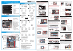
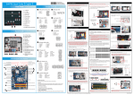
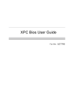
62R-SZ77R0-0601 SZ77R5 English.Spanish.Korean. Traditional Chinese.Japanese. French. German Quick Guide SZ77R5 Quick Guide【 English 】 Please do not apply excess amount of thermal paste. Jumper Settings Front Panel D. Mini PCIe card Installation A. Begin Installation For safety reasons, please ensure that the power cord is disconnected before opening the case. 9. Tear off the protective membrane from the bottom of ICE module. Remove the protective socket mylar from the CPU socket. 1. Unscrew 3 thumbscrews of the chassis cover. F1. 5.25” Bay F3 F1 S/PDIF OutPut Connector (JP2) J1 1=Ground 2=VCC 3=SPDIFO F2. 3.5” Bay F3. Eject Button F4. Open Door F2 F4 COM Header (COM1) J3 F7. USB3.0 Ports 1=DCD 3=TXD 5=Ground 7=RTS 9=Ring F9. Mic In F10.Headphone J5 Back Panel B15 B15 2=RXD 4=DTR 6=DSR 8=CTS 10=NA 1. Loosen the purse lock and separate the Serial ATA and power cables. 1 2. Place the HDD and optical drive in the rack and secure with screws from the side. Fan Connector 3. Unfasten the rack mount screws and remove the rack. 2=PWR_LED 4=GND 6=PWR_SW 8=GND 10=NA 10 8 6 4 2 10 8 6 4 2 1=5V_USB 3=USB A- 5=USB A+ 7=GND 9=NA B9.Front Speaker Out (L/R) Port Serial ATA Optical Drive 12. Fasten the Smart Fan to the chassis with the 4 thumbscrews. Serial ATA HDD 3. Place the rack in the chassis and refasten the rack. J6 B. CPU and ICE Installation 1. Unfasten the ICE fan thumbscrews on the back of the chassis. CPU Fan Connectors SPEED_SENSE +12V PWM_CTRL 2. Unfasten the four ICE module attachment screws and unplug the fan connector. Ground B13 B12 C. Memory module Installation Guidelines for Memory Configuration Before installing DIMMs, read and follow these guidelines for memory configuration. Make sure that the motherboard supports the memory. It is recommended that memory of the same capacity, brand, speed,and chips are used. (Go to Shuttle's website for the latest memory support list.) Memory modules have a foolproof design. A memory module can be installed in only one direction. If you are unable to insert the memory, switch the direction. FAN1/ FAN2 Fan Connector 9 7 5 3 1 2=5V_USB 4=USB B6=USB B+ 8=GND 10=NULL 10 8 6 4 2 B10.Side Speaker Out (L/R) Port B11.Real Speaker Out (L/R) Port B11 LPC Header (JP1) J8 B12.Center/Subwoofer Speaker Out Port B13.Line-In Port B15.Wireless LAN Perforation (Optional) 3. Remove the ICE module from the chassis and put it aside. Dual-Channel mode Population Rule This 1155 pin socket is fragile and easily damaged. Always use extreme care when installing a CPU and limit the number of times that you remove or change the CPU. Before installing the CPU, make sure to turn off the computer and unplug the power cord from the power outlet to prevent damage to the CPU. Follow the steps below to correctly install the CPU into the motherboard CPU socket. 1=+12V 5=CLK_48M 9=LAD3 13=Ring 17=LAD0 B14.LAN & USB2.0 Ports B5 5 USB Header (USB1,USB2) J7 B8.Clear CMOS Button B1 B4 4 Power Header (JP3) 4 3 2 1 B7.USB3.0 Ports B8 B9 B10 3 B2.Serial Port (Optional) B6.eSATA & USB2.0 Ports B6 B7 2 9 7 5 3 1 AUX IN Connector B1.AC Power Socket B5.HDMI Port B3 1 1=+HD_LED 3=-HD_LED 5=RST_SW 7=GND 9=NULL 1=AUX-IN – Left 2=Ground 3=Ground 4=AUX-IN – Right B4.DVI-I Port B14 E. Peripheral Installation 2 9 7 5 3 1 B3.S/PDIF Out Port B2 11. Connect the fan connector. F11.USB2.0 Port & Fast Charger F8 F9 F10 F11 B15 J4 10. Screw the ICE module to the mainboard. Note to press down on the opposite diagonal corner while tightening each screw. 2. Slide the cover backwards and upwards. F5. Power Switch & Power LED F8. USB2.0 Port F7 CIR Header (JP6) 1=5V 2=NA 3=Ground 4=GPIO1 5=GPIO2 1 2 3 F6. HDD LED F6 F5 J2 3=5VSB 7=SIO_RST 11=-12V 15=SIO_PME 19=GND 2=5V 6=CLK_33M 10=LAD2 14=LDRQ0 18=+3.3V 1. Install the Mini PCIe card into the Mini PCIe slot / mSATA Slot and affix it with screws. 4=SERIRQ 8=LFRAME 12=3VSB 16=LAD1 20=NA 11 12 13 14 15 16 17 18 19 20 4. First unlock. Press A with your thumb, then move it to B until it is released from the retention tab and raise the socket lever. 4. Connect the Serial ATA and power cables to the HDD. Serial ATA Power Cable Serial ATA Cable 5. Connect the Serial ATA and power cables to the optical drive. In Dual-Channel mode, the memory modules can transmit and receive data with two data bus lines simultaneously. Enabling Dual-Channel mode can enhance the system performance. The following illustrations explain the population rules for Dual-Channel mode. Serial ATA Power Cable Serial ATA Cable A DIMM1 (Red),Empty DIMM2 (Yellow),Installed F. Accessories Installation DIMM3 (Red),Empty DIMM4 (Yellow),Installed 1. Unfasten expansion slot bracket screws. Remove the back panel bracket and put the bracket aside. B The maximum size acceptable for display cards is 267mm x 98mm x 34.6mm. DIMM1 (Red),Installed A Connect the Serial ATA Cable to motherboard. DIMM2 (Yellow),Installed DIMM3 (Red),Installed 1 Motherboard Illustration Clear CMOS Button Front Speaker Out / Line-In Ports Side Speaker Out / Real Speaker Out / Center / Subwoofer Speaker Out Port J10 USB Header-USB2 One PCIe x4 Slot 4 5 6 7 8 9 10 1=5VCC 5=A_TX_N 9=A_Data_P 13=Ground 17=B_RX_P 2x USB 2.0 & 1x LAN Ports 2x USB 3.0 Ports 2x USB 2.0 & eSATA Ports HDMI & DVI-I Port 5. Lift the metal load plate on the CPU socket. Installing a memory module 2=A_RX_N 6=A_TX_P 10=OC 14=B_TX_P 18=B_RX_N 3=A_RX_P 7=Ground 11=B_Data_P 15=B_TX_N 19=5VCC 4=Ground 8=A_Data_N 12=B_Data_N 16=Ground 20=NA J8 AUX_IN Connector Mini PCIe slot with mSATA support J3 S/PDIF OutPut J1 Connector-JP2 USB Header-USB1 J4 J2 Power Header-JP3 CIR Header-JP6 1. Unlock the DIMM latch. 2. Align the memory module's cutout with the DIMM slot notch. Slide the memory module into the DIMM slot. DO NOT touch socket contacts. To protect the CPU socket, always replace the protective socket cover when the CPU is not installed. 1 J7 Intel® 64 Chipset J10 2 3 4 5 6 LGA 1155 7 8 9 2. Install the PCIe x4 / PCIe x16 card into the PCIe x4 / PCIe x16 slots. 2=GND 4=Front_Detect 6=Mic_detect 8=NA 10=Line_Detect Socket 1155 CPU Notch 48*2=96 pin 2 10 8 6 4 2 DDR3 240-pin 1.5V Cutout 72*2=144 pin PCIe x16 / PCIe x 4 slots 3 Read the following precautions before setting up a Shuttle XPC. CAUTION ATX Power Connector-ATX1 Incorrectly replacing the battery may damage this computer. Replace only with the same or equivalent as recommended by Shuttle. Disposal of used batteries according to the manufacturer's instructions. 4x 240 pins DDR3 DIMM Slots Laser compliance statement The optical disc drive in this PC is a laser product. The drive's classification label is located on the drive. CLASS 1 LASER PRODUCT EAUTION INVISIBLE LASER RADIATION WHEN OPEN. AVOID EXPOSURE TO BEAM. Chassis Cover Latch G. Complete 1. Replace the cover and refasten the thumbscrews. Safety Information ATX Power Connector-PWR1 Triangle Pin1 Marking on the CPU 34.6mm 1 Latch 9 7 5 3 1 VGA Card PCB 5mm 6. Orientate the CPU and socket, you may align the CPU notches with the socket alignment keys. Make sure the CPU is perfectly horizontal, insert the CPU into the socket. 10 Front Audio Header (JP5) 1=MIC_L 3=MIC_R 5=LINE_R 7=sense 9=LINE_L COM Header-COM1 SATA 2.0 Connector -SATA3,SATRA4 PCIe x16 slot A DDR3 memory module has a cutout, so it can only fit in one direction. J5 LPC Header-JP1 Mini PCIe Slot CPU FAN Connector-FAN1 Remove the protective membrane PCIe x4 slot 3. Secure the bracket. SATA 3.0 Connector -SATA1,SATA2 USB3.0 Header-JP4 DDR3 and DDR2 DIMMs are not compatible to each other or DDR DIMMs. Be sure to install DDR3 DIMMs on this motherboard. Follow the steps below to correctly install your memory modules in the memory sockets. Metal load plate 11 12 13 14 15 16 17 18 19 20 CPU FAN Connector-FAN2 J9 DIMM4 (Yellow),Installed USB 3.0 Header (JP4) J9 One PCIe x16 Slot J6 3 Front Audio Header-JP5 J7 J6 2 B Please be aware of the CPU orientation, DO NOT force the CPU into the socket to avoid bending of pins on the socket and damage of CPU! 3. Check that the latches are closed, and the memory module is firmly installed. 7. Close the metal load plate, lower the CPU socket lever and lock in place. 8. Spread thermal paste evenly on the CPU surface. 2. Complete. Thermal Paste application area Repeat the above steps to install additional memory modules, if required. LThe product’s colour and specification will depend on the actual shipping product. Please press "Del" key while booting to enter BIOS and load the optimised BIOS settings. 53R-SZ77R3-2001