Transcript
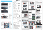
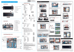
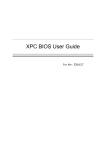
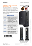
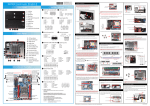
62R-DS4370-0601 English.Spanish.Korean. Traditional Chinese.Japanese. French. German Quick Guide DS437 Quick Guide【 English 】 __p F1. USB2.0 Ports x4 Front Panel F1 F2 C10 Motherboard Illustration Back F5 F6 Pin Assignments: 1=V_BAT 2=GND 1=-FANIO2 2=GND 3=FANPEM2 1 Super I/O F3. HDD LED F4. Power Button C13 F5. COM 1 : C12 Support RS232/RS422/RS485 (Audio2): F4 F7 F7. SD Card Reader Back Panel B2 1=PULL AGND 2=LINE-R 3=N/C 4=LINE-L 5=PULL AGND 6=FRONT_L 7=N/C 8=PRONT_SENSE 9=PULL AGND 10=FRONT_R Intel® NM70 Chipset Support RS232 Intel® Celeron® Processor 1037U B1. C-MOS Port B5. Headphone B7. LAN Ports x2 B5 B6 B7 B8 1=PWRSW2=+5V 3=GND 4=Clear Cmos 1 3 Read the following precautions before setting up a Shuttle XPC. CAUTION 14 12 10 8 6 4 2 Incorrectly replacing the battery may damage this computer. Replace only with the same or equivalent as recommended by Shuttle. Dispose of used batteries according to the manufacturer's instructions. C. Component Installation 1. As shown, unfasten the screw first. Install the Mini PCIe card into the Mini PCIe slot and affix it with a screw. Mini PCIe slot 1 Jumper Settings Panel Voltage Select C6 1 1=+3.3V 2=Panel_VDD 3=+5.0V 2 3 C2 1=-XRI1 3=-XRI2 5=+5V 7=COM1_PWR 9=+12V Power Button Pin Assignments (SW3) Motherboard Illustration Front C7 C3 Converter Voltage Select - JP4 Power Button - SW3 C2 C4 Fan Connector - Fan1 HDD LED COM Port 1 Power LED COM Port 2 C5 Power connector - SW1 C6 COM1&COM2 Power Switch - JP2 C7 SMBUS USB 2.0 Ports x4 C3 3. Place the HDD in the rack and secure with the two screws from the side. 2 2=COM_-XRI1 4=COM_-XRI2 6=+5V 8=COM2_PWR 10=+12V 2 4 6 8 10 1 3 5 7 LVDS Connector - LVDS1 C9 J1 AUTO PWR_SW 3 2 1 C8 B. Memory Module Installation Pin Assignments (FAN1): 1=Ground 2=+12V 3=SPEED_SENSE 4=PWM_CTRL 1 2 3 4 C10 Battery Connector - CN1 C11 Fan2 Connector DDR3 SODIMM slots C5 Power Connector Pin Assignments (SW1): Mini PCIe Slot - CN3 C12 Audio Connector - AUDIO2 DVI-I Port C13 CMOS Port - SW2 USB 3.0 Ports x2 C11 HDMI Port 1. Locate the SODIMM slot on the mainboard. 2. Align the notch of the memory module with the one of the memory slot. 1 1=+HD_LED 2=PWR_LED 3=-HD_LED 4=GND 5=RST_SW 6=PWR_SW 7=GND 8=GND 9=NUUL 4. Put the HDD in the chassis and push toward right untill it inserts into the SATA&SATA Power Connector. SODIMM slot notch LVDS Connector Pin Assignments (LVDS1): C4 FAN_1 connector Mini PCIe slot with mSATA support - PCIE1 C8 9 Pin Assignments (JP4): 1=+12V 2=INV_PWR_SRC 3=+5V 1 SMBUS 1=SMBCLK_SB 2=SMBDATA_SB 3=+5V 4=GND Converter Voltage Select 3 2. Slide the cover forwards and upwards. Pin Assignments: Panel Voltage C1 Select - JP3 Screw COM1&COM2 Power Switch Pin Assignments (JP2): Kensington® Lock Port 2 2. Unscrew the rack from the chassis. JUMP1 Connector Pin 1 and Pin 2 = RI1 Signal. JUMP2 Connector Pin 3 and Pin 4 = RI2 Signal. IF JUMP1 Connector Pin 5 and Pin 7 = RI1 is VCC IF JUMP2 Connector Pin 6 and Pin 8 = RI2 is VCC IF JUMP1 Connector Pin 7 and Pin 9 = RI1 is 12V IF JUMP2 Connector Pin 8 and Pin 10 = RI2 is 12V Pin Assignments (JP3): Kensington® Lock Port Headphone Mic In 3 1 B8. DC IN C1 DC IN 5 1. Unscrew the two screws of the chassis cover. Left / Right Panel LAN Ports x2 4 7 For safety reasons, please ensure that the power cord is disconnected before opening the case. B6. USB3.0 Ports x2 2.5 inch HDD slot 2 Safety Information 13 11 9 A. Begin Installation B4. Mic-In B4 11=BK_AUDIO-JD 12=MIC1_R 13=AGND 14=MIC1_L Pin Assignments (SW2): B2. DVI-I Port B3 B3. HDMI Port B1 1 CMOS Port Audio Connector Pin Assignments F6. COM 2 : FAN2 connector C11 Pin Assignments (CN1): F2. Power LED F3 Battery Connector 1 2 3 4 5 6 7 8 9 1=N/C 2=Converter-PWR 3=N/C 4=Converter-PWR 5=N/C 6=Converter-PWR 7=GND 8=Converter-PWR 9=N/C 10=GND 11=GND 12=LVDS_DDAT 13=PWMO 14=LVDS_DCLK 15=GND 16=Panel_VDD 17=BKLTEN 18=Panel_VDD 19=PWMO 20=Panel_VDD 31=LVDS_ACK_N 32=LVDS_BCK_N 33=GND 34=GND 35=LVDS_A2P 36=LVDS_B2P 37=LVDS_A2N 38=LVDS_B2N 39=GND 40=GND 41=LVDS_A1P 42=LVDS_B1P 43=LVDS_A1N 44=LVDS_B1N 45=GND 46=GND 47=LVDS_A0P 48=LVDS_B0P 49=LVDS_A0N 50=LVDS_B0N 21=GND 22=GND 23=LVDS_A3P 24=LVDS_B3P 25=LVDS_A3N 26=LVDS_B3N 27=GND 28=GND 29=LVDS_ACK_P 30=LVDS_BCK_P 50 5. Refasten the screw. 3. Gently insert the module into the slot in a 45-degree angle. 4. Carefully push down the memory module until it snaps into the locking mechanism. 1 D. Complete 49 2 1. Replace the covers and refasten the screws. 45-degree angle 3 C9 J1 AUTO PWR_SW Pin Assignments: SHORT=Disabled OPEN=Enabled 2 1 2 . Complete. 1 Please load the optimized BIOS settings. Latch Latch 5. Repeat the above steps to install additional memory modules, if required. LThe product’s color and specification will depend on the actual shipping product. Operation Position: 1) Device must only be used in vertical position with the DVI port facing up. 2) Please make sure to use either the supplied feet or the VESA mount. 53R-DS4373-2201