1
Hardware Maintenance Manual
Lenovo B590
Note: Before using this information and the product it supports, be sure to read the general information
under Appendix A “Notices” on page 95.
Third Edition (April 2013)
© Copyright Lenovo 2012.
LIMITED AND RESTRICTED RIGHTS NOTICE: If data or software is delivered pursuant a General Services Administration
“GSA” contract, use, reproduction, or disclosure is subject to restrictions set forth in Contract No. GS-35F-05925.
Contents
About this manual. . . . . . . . . . .
iii
Screw notices . . . . . . . . . . . . . . .
41
Chapter 1. Safety information . . . . . . 1
Chapter 7. Removing and replacing a
FRU . . . . . . . . . . . . . . . . . .
43
General safety . . . . . . . . . . . . . . .
Electrical safety . . . . . . . . . . . . . .
Safety inspection guide . . . . . . . . . . .
Handling devices that are sensitive to electrostatic
discharge. . . . . . . . . . . . . . . . .
Grounding requirements . . . . . . . . . . .
Safety notices (multilingual translations) . . . . .
Laser compliance statement (multilingual
translations) . . . . . . . . . . . . . . . .
Chapter 2. Important service
information . . . . . . . . . . . . . .
Strategy for replacing FRUs . . . . . . .
Strategy for replacing a hard disk drive .
Important notice for replacing a system
board . . . . . . . . . . . . . .
Important information about replacing RoHS
compliant FRUs . . . . . . . . . . . .
.
.
.
1
2
3
.
.
.
3
4
4
19
27
. .
. .
27
28
. .
28
. .
28
Chapter 3. General checkout . . . . .
29
What to do first . . . . . . . .
Power system checkout . . . . .
Checking the ac power adapter
Checking operational charging
Checking the battery pack . .
.
.
.
.
.
29
30
30
31
31
Chapter 4. Related service
information . . . . . . . . . . . . . .
33
Recovering the computer settings
Passwords . . . . . . . . .
Power-on password . . . .
Supervisor password . . .
Power management . . . . .
Screen blank mode . . . .
Sleep mode . . . . . . .
Hibernation mode . . . .
.
.
.
.
.
.
.
.
.
.
.
.
.
.
.
.
.
.
.
.
.
.
.
.
.
.
.
.
.
.
.
.
.
.
.
.
.
.
.
.
.
.
.
.
.
.
.
.
.
.
.
.
.
.
.
.
.
.
.
.
.
.
.
.
.
.
.
.
.
.
.
.
.
.
.
.
.
.
.
.
.
33
33
34
34
34
34
34
35
Chapter 5. Lenovo B590 . . . . . . . .
37
Specifications . . . . . . . . . . . . . . .
Status indicators . . . . . . . . . . . . . .
Fn key combinations . . . . . . . . . . . .
37
38
39
Chapter 6. FRU replacement
notices . . . . . . . . . . . . . . . .
© Copyright Lenovo 2012
41
General guidelines . . . . . . . . . . .
1010 Battery pack . . . . . . . . . . .
1020 Bottom slot cover . . . . . . . . .
1030 Optical drive . . . . . . . . . . .
1040 Memory modules . . . . . . . . .
1050 Hard disk drive assembly . . . . . .
1060 PCI Express Mini Card for wireless LAN
1070 mSATA solid state drive . . . . . . .
1080 Backup battery . . . . . . . . . .
1090 Keyboard . . . . . . . . . . . .
1100 Keyboard bezel . . . . . . . . . .
1110 LED board . . . . . . . . . . . .
1120 Power board and touch pad bracket . .
1130 Microphone assembly . . . . . . .
1140 I/O board . . . . . . . . . . . .
1150 System board assembly and USB board
1160 DC-in connector . . . . . . . . . .
1170 Thermal module . . . . . . . . . .
1180 CPU . . . . . . . . . . . . . .
1190 LCD unit . . . . . . . . . . . . .
1210 Speaker assembly and base cover . .
2010 LCD front bezel . . . . . . . . . .
2020 Camera . . . . . . . . . . . . .
2030 LCD panel, LCD cable, and hinges . .
2040 Antenna assembly and LCD rear cover .
.
.
.
.
.
.
.
.
.
.
.
.
.
.
.
.
.
.
.
.
.
.
.
.
.
43
44
44
45
46
47
49
51
52
53
56
58
59
60
61
62
65
66
68
69
71
73
74
75
77
Chapter 8. Locations . . . . . . . . .
79
Right-side view . . . . . . . . . . . . . .
Bottom view . . . . . . . . . . . . . . .
79
80
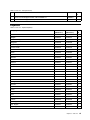
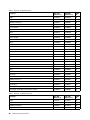
Chapter 9. Parts list . . . . . . . . . .
81
Overall . . . . . .
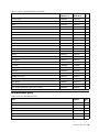
LCD FRUs . . . .
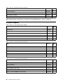
Keyboard . . . . .
Miscellaneous parts
ac power adapters .
Power cords . . .
.
.
.
.
.
.
.
.
.
.
.
.
.
.
.
.
.
.
.
.
.
.
.
.
.
.
.
.
.
.
.
.
.
.
.
.
.
.
.
.
.
.
.
.
.
.
.
.
.
.
.
.
.
.
.
.
.
.
.
.
.
.
.
.
.
.
.
.
.
.
.
.
.
.
.
.
.
.
.
.
.
.
.
.
.
.
.
.
.
.
.
.
.
.
.
.
.
82
85
87
89
90
91
Appendix A. Notices . . . . . . . . . .
95
Electronic emissions notices . . . . . . . . .
Trademarks . . . . . . . . . . . . . . . .
96
96
i
ii
Hardware Maintenance Manual
About this manual
This manual provides service and reference information for the following Lenovo® products.
Machine
Machine type (MT)
Lenovo B590
3761, 6274, 20206, 20208
Use this manual to troubleshoot problems.
The manual is divided into the following sections:
• The common sections provide general information, guidelines, and safety information required for
servicing computers.
• The product-specific section includes service, reference, and product-specific parts information.
Important:
• This manual is intended only for trained service technicians who are familiar with Lenovo products. Use
this manual to troubleshoot problems effectively.
• Before servicing a Lenovo product, be sure to read all the information under Chapter 1 “Safety
information” on page 1 and Chapter 2 “Important service information” on page 27.
© Copyright Lenovo 2012
iii
iv
Hardware Maintenance Manual
Chapter 1. Safety information
This chapter presents following safety information that you need to be familiar with before you service a
Lenovo Notebook.
• “General safety” on page 1
• “Electrical safety” on page 2
• “Safety inspection guide” on page 3
• “Handling devices that are sensitive to electrostatic discharge” on page 3
• “Grounding requirements” on page 4
• “Safety notices (multilingual translations)” on page 4
• “Laser compliance statement (multilingual translations)” on page 19
General safety
Follow these rules to ensure general safety:
• Observe good housekeeping in the area of the machines during and after maintenance.
• When lifting any heavy object:
1. Make sure that you can stand safely without slipping.
2. Distribute the weight of the object equally between your feet.
3. Use a slow lifting force. Never move suddenly or twist when you attempt to lift.
4. Lift by standing or by pushing up with your leg muscles; this action removes the strain from the
muscles in your back. Do not attempt to lift any object that weighs more than 16 kg (35 lb) or that you
think is too heavy for you.
• Do not perform any action that causes hazards to the customer, or that makes the equipment unsafe.
• Before you start the machine, make sure that other service technicians and the customer's personnel are
not in a hazardous position.
• Place removed covers and other parts in a safe place, away from all personnel, while you are servicing
the machine.
• Keep your toolcase away from walk areas so that other people will not trip over it.
• Do not wear loose clothing that can be trapped in the moving parts of a machine. Make sure that your
sleeves are fastened or rolled up above your elbows. If your hair is long, fasten it.
• Insert the ends of your necktie or scarf inside clothing or fasten it with a nonconductive clip, about 8
centimeters (3 inches) from the end.
• Do not wear jewelry, chains, metal-frame eyeglasses, or metal fasteners for your clothing, because metal
objects are good electrical conductors.
• Wear safety glasses when you are hammering, drilling, soldering, cutting wire, attaching springs, using
solvents, or working in any other conditions that might be hazardous to your eyes.
• After service, reinstall all safety shields, guards, labels, and ground wires. Replace any safety device
that is worn or defective.
• Reinstall all covers correctly before returning the machine to the customer.
• Fan louvers on the machine help to prevent overheating of internal components. Do not obstruct fan
louvers or cover them with labels or stickers.
© Copyright Lenovo 2012
1
Electrical safety
Observe the following rules when working on electrical equipment.
Important:
Use only approved tools and test equipment. Some hand tools have handles covered with a soft material
that does not insulate you when working with live electrical currents.
Many customers have, near their equipment, rubber floor mats that contain small conductive fibers to
decrease electrostatic discharges. Do not use this type of mat to protect yourself from electrical shock.
• Find the room emergency power-off (EPO) switch, disconnecting switch, or electrical outlet. If an electrical
accident occurs, you can then operate the switch or unplug the power cord quickly.
• Do not work alone under hazardous conditions or near equipment that has hazardous voltages.
• Disconnect all power before:
– Performing a mechanical inspection
– Working near power supplies
– Removing or installing main units
• Before you start to work on the machine, unplug the power cord. If you cannot unplug it, ask the customer
to power-off the wall box that supplies power to the machine, and to lock the wall box in the off position.
• If you need to work on a machine that has exposed electrical circuits, observe the following precautions:
– Ensure that another person, familiar with the power-off controls, is near you.
Attention: Another person must be there to switch off the power, if necessary.
– Use only one hand when working with powered-on electrical equipment; keep the other hand in your
pocket or behind your back.
Attention: An electrical shock can occur only when there is a complete circuit. By observing the above
rule, you may prevent a current from passing through your body.
– When using testers, set the controls correctly and use the approved probe leads and accessories for
that tester.
– Stand on suitable rubber mats (obtained locally, if necessary) to insulate you from grounds such as
metal floor strips and machine frames.
Observe the special safety precautions when you work with very high voltages; Instructions for these
precautions are in the safety sections of maintenance information. Use extreme care when measuring
high voltages.
• Regularly inspect and maintain your electrical hand tools for safe operational condition.
• Do not use worn or broken tools and testers.
• Never assume that power has been disconnected from a circuit. First, check that it has been powered off.
• Always look carefully for possible hazards in your work area. Examples of these hazards are moist floors,
nongrounded power extension cables, power surges, and missing safety grounds.
• Do not touch live electrical circuits with the reflective surface of a plastic dental mirror. The surface is
conductive; such touching can cause personal injury and machine damage.
• Do not service the following parts with the power on when they are removed from their normal operating
places in a machine:
– Power supply units
– Pumps
– Blowers and fans
– Motor generators
– Similar units to listed above
This practice ensures correct grounding of the units.
• If an electrical accident occurs:
2
Hardware Maintenance Manual
– Use caution; do not become a victim yourself.
– Switch off power.
– Send another person to get medical aid.
Safety inspection guide
The purpose of this inspection guide is to assist you in identifying potentially unsafe conditions. As each
machine was designed and built, required safety items were installed to protect users and service technicians
from injury. This guide addresses only those items. You should use good judgment to identify potential
safety hazards due to attachment of non-Lenovo features or options not covered by this inspection guide.
If any unsafe conditions are present, you must determine how serious the apparent hazard could be and
whether you can continue without first correcting the problem.
Consider these conditions and the safety hazards they present:
• Electrical hazards, especially primary power (primary voltage on the frame can cause serious or fatal
electrical shock)
• Explosive hazards, such as a damaged CRT face or a bulging capacitor
• Mechanical hazards, such as loose or missing hardware
To determine whether there are any potentially unsafe conditions, use the following checklist at the beginning
of every service task. Begin the checks with the power off, and the power cord disconnected.
Checklist:
1. Check exterior covers for damage (loose, broken, or sharp edges).
2. Power off the computer. Disconnect the power cord.
3. Check the power cord for:
a. A third-wire ground connector in good condition. Use a meter to measure third-wire ground
continuity for 0.1 ohm or less between the external ground pin and the frame ground.
b. The power cord should be the type specified in the parts list.
c. Insulation must not be frayed or worn.
4. Check for cracked or bulging batteries.
5. Remove the cover.
6. Check for any obvious non-Lenovo alterations. Use good judgment as to the safety of any non-Lenovo
alterations.
7. Check inside the unit for any obvious unsafe conditions, such as metal filings, contamination, water or
other liquids, or signs of fire or smoke damage.
8. Check for worn, frayed, or pinched cables.
9. Check that the power-supply cover fasteners (screws or rivets) have not been removed or tampered with.
Handling devices that are sensitive to electrostatic discharge
Any computer part containing transistors or integrated circuits (ICs) should be considered sensitive to
electrostatic discharge (ESD.) ESD damage can occur when there is a difference in charge between objects.
Protect against ESD damage by equalizing the charge so that the machine, the part, the work mat, and the
person handling the part are all at the same charge.
Notes:
1. Use product-specific ESD procedures when they exceed the requirements noted here.
Chapter 1. Safety information
3
2. Make sure that the ESD protective devices you use have been certified (ISO 9000) as fully effective.
When handling ESD-sensitive parts:
• Keep the parts in protective packages until they are inserted into the product.
• Avoid contact with other people.
• Wear a grounded wrist strap against your skin to eliminate static on your body.
• Prevent the part from touching your clothing. Most clothing is insulative and retains a charge even when
you are wearing a wrist strap.
• Use a grounded work mat to provide a static-free work surface. The mat is especially useful when
handling ESD-sensitive devices.
• Select a grounding system, such as those listed below, to provide protection that meets the specific
service requirement.
Note: The use of a grounding system to guard against ESD damage is desirable but not necessary.
– Attach the ESD ground clip to any frame ground, ground braid, or green-wire ground.
– When working on a double-insulated or battery-operated system, use an ESD common ground or
reference point. You can use coax or connector-outside shells on these systems.
– Use the round ground prong of the ac plug on ac-operated computers.
Grounding requirements
Electrical grounding of the computer is required for operator safety and correct system function. Proper
grounding of the electrical outlet can be verified by a certified electrician.
Safety notices (multilingual translations)
The safety notices in this section are provided in the following languages:
• English
• Arabic
• Brazilian Portuguese
• French
• German
• Hebrew
• Japanese
• Korean
• Spanish
• Traditional Chinese
DANGER
DANGER
4
Hardware Maintenance Manual
DANGER
DANGER
DANGER
DANGER
DANGER
Chapter 1. Safety information
5
DANGER
6
Hardware Maintenance Manual
Chapter 1. Safety information
7
PERIGO
PERIGO
PERIGO
PERIGO
PERIGO
PERIGO
8
Hardware Maintenance Manual
PERIGO
PERIGO
DANGER
DANGER
DANGER
Chapter 1. Safety information
9
DANGER
DANGER
DANGER
DANGER
DANGER
VORSICHT
10
Hardware Maintenance Manual
VORSICHT
VORSICHT
VORSICHT
VORSICHT
Chapter 1. Safety information
11
VORSICHT
VORSICHT
VORSICHT
12
Hardware Maintenance Manual
Chapter 1. Safety information
13
14
Hardware Maintenance Manual
Chapter 1. Safety information
15
16
Hardware Maintenance Manual
Chapter 1. Safety information
17
18
Hardware Maintenance Manual
Laser compliance statement (multilingual translations)
The laser compliance statements in this section are provided in the following languages:
• English
• Arabic
• Brazilian Portuguese
• French
• German
• Hebrew
• Japanese
• Korean
• Spanish
• Traditional Chinese
Chapter 1. Safety information
19
20
Hardware Maintenance Manual
Chapter 1. Safety information
21
22
Hardware Maintenance Manual
Chapter 1. Safety information
23
24
Hardware Maintenance Manual
Chapter 1. Safety information
25
26
Hardware Maintenance Manual
Chapter 2. Important service information
This chapter presents the following important service information that applies to all machine types supported
by this manual:
• “Strategy for replacing FRUs” on page 27
– “Strategy for replacing a hard disk drive” on page 28
– “Important notice for replacing a system board” on page 28
• “Important information about replacing RoHS compliant FRUs” on page 28
Important: BIOS and device driver fixes are customer-installable. The BIOS and device drivers are available
at http://www.lenovo.com/support.
Strategy for replacing FRUs
Before replacing parts:
Make sure that all software fixes, drivers, and BIOS downloads are installed before replacing any FRUs
listed in this manual.
After a system board is replaced, ensure that the latest BIOS is installed to the system board before
completing the service action.
To download software fixes, drivers, and BIOS, do the following:
1. Go to http://www.lenovo.com/support.
2. Click Download Drivers & Software. The Web site offers three options to begin your search:
• Search by product number
• Search through the product auto-detect function
• Search by product category
3. Follow the directions on the screen and install the necessary software.
4. Restart the computer.
Notes: If you need to improve the computer performance, you also could download and install the latest
BIOS utility from the Support Web site.
• Do not try to update the BIOS settings for any computer unless you have been trained and certified. An
untrained person runs the risk of damaging the computer.
• Before installing the latest utility, make sure that the battery is fully charged and an ac power adapter is
connected.
• Do not turn off or put your computer into sleep or hibernation until the update has been completed.
Otherwise, the system board might be damaged.
Use the following strategy to prevent unnecessary expense for replacing and servicing FRUs:
• If you are instructed to replace a FRU but the replacement does not correct the problem, reinstall
the original FRU before you continue.
• Some computers have both a processor board and a system board. If you are instructed to replace either
the processor board or the system board, and replacing one of them does not correct the problem,
reinstall that board, and then replace the other one.
© Copyright Lenovo 2012
27
• If an adapter or a device consists of more than one FRU, any of the FRUs may be the cause of the error.
Before replacing the adapter or device, remove the FRUs, one by one, to see if the symptoms change.
Replace only the FRU that changed the symptoms.
Strategy for replacing a hard disk drive
Always try to run a low-level format before replacing a hard disk drive (HDD). This will cause all customer data
on the hard disk to be lost. Be sure that the customer has a current backup of the data before doing this task.
Attention: The drive startup sequence in the computer you are servicing may have been changed. Be
extremely careful during write operations such as copying, saving, or formatting. If you select an incorrect
drive, data or programs can be overwritten.
Important notice for replacing a system board
Some components mounted on a system board are very sensitive. Improper handling of a system board can
cause damage to those components, and may cause a system malfunction.
Attention: When handling a system board:
• Do not drop a system board or apply any excessive force to it.
• Avoid rough handling of any kind.
• Avoid bending a system board and hard pushing to prevent cracking at each BGA (Ball Grid Array) chipset.
Important information about replacing RoHS compliant FRUs
RoHS, The Restriction of Hazardous Substances in Electrical and Electronic Equipment Directive
(2002/95/EC) is a European Union legal requirement affecting the global electronics industry. RoHS
requirements must be implemented on Lenovo products placed on the market after June 2006. Products
on the market before June 2006 are not required to have RoHS compliant parts. If the original FRU parts
are non-compliant, the replacement parts also can be non-compliant. That is, if the original FRU parts are
RoHS compliant, the replacement part also must be RoHS compliant.
Note: RoHS and non-RoHS FRU part numbers with the same fit and function are identified by the unique
FRU part numbers.
Lenovo plans to transit to RoHS compliance before the implementation date and expects its suppliers to be
ready to meet Lenovo’s requirements and schedule in the European Union. Products sold between 2005
and 2006 might contain some RoHS compliant FRUs. The following statement pertains to the products
with RoHS compliant FRUs.
RoHS compliant FRUs have unique FRU part numbers. Before or after the RoHS implementation date, the
failed RoHS compliant parts must be replaced with compliant parts and only the following FRUs can be
used: identified as compliant in the Hardware Maintenance Manual or direct substitutions can be used.
• Compliant FRUs identified in Hardware Maintenance Manual
• Direct substitutions with different FRU part numbers automatically shipped by the distribution center at
the time of order
For products shipped after June 2006
Current or original part
Replacement FRU
Must be RoHS
Must be RoHS
28
Hardware Maintenance Manual
Chapter 3. General checkout
This chapter presents following information:
• “What to do first” on page 29
• “Power system checkout” on page 30
Before you go to the checkout guide, be sure to read the following important notes.
Important notes:
• Only certified trained personnel should service the computer.
• Before replacing any FRU, read the entire page on removing and replacing FRUs.
• When you replace FRUs, it is recommended to use new nylon-coated screws.
• Be extremely careful during such write operations as copying, saving, or formatting. Drives in the computer
that you are servicing sequence might have been altered. If you select an incorrect drive, data or programs
might be overwritten.
• Replace a FRU only with another FRU of the correct model. When you replace a FRU, make sure that the model
of the machine and the FRU part number are correct by referring to the FRU parts list.
• A FRU should not be replaced because of a single, unreproducible failure. Single failures can occur for a
variety of reasons that have nothing to do with a hardware defect, such as cosmic radiation, electrostatic discharge,
or software errors. Consider replacing a FRU only when a problem recurs. If you suspect that a FRU is defective,
clear the error log and run the test again. If the error does not recur, do not replace the FRU.
• Be careful not to replace a nondefective FRU.
What to do first
When you do return a FRU, you must include the following information in the parts exchange form or
parts return form that you attach to it:
1. Name and phone number of service technician
2. Date of service
3. Date on which the machine failed
4. Date of purchase
5. Procedure index and page number in which the failing FRU was detected
6. Failing FRU name and part number
7. Machine type, model number, and serial number
8. Customer's name and address
Note: During the warranty period, the customer may be responsible for repair costs if the computer damage
was caused by misuse, accident, modification, unsuitable physical or operating environment, or improper
maintenance by the customer. Following is a list of some common items that are not covered under warranty
and some symptoms that might indicate that the system was subjected to stress beyond normal use.
Before checking problems with the computer, determine whether the damage is covered under the warranty
by referring to the following list:
The following are not covered under warranty:
• LCD panel cracked from the application of excessive force or from being dropped
• Scratched (cosmetic) parts
• Distortion, deformation, or discoloration of the cosmetic parts
• Plastic parts, latches, pins, or connectors that have been cracked or broken by excessive force
• Damage caused by liquid spilled into the system
• Damage caused by the improper insertion of a PC Card or the installation of an incompatible card
• Improper disc insertion or use of an optical drive
© Copyright Lenovo 2012
29
• Diskette drive damage caused by pressure on the diskette drive cover, foreign material in the drive,
or the insertion of a diskette with multiple labels
• Damaged or bent diskette eject button
• Fuses blown by attachment of a nonsupported device
• Forgotten computer password (making the computer unusable)
• Sticky keys caused by spilling a liquid onto the keyboard
• Use of an incorrect ac power adapter on laptop products
The following symptoms might indicate damage caused by nonwarranted activities:
• Missing parts might be a symptom of unauthorized service or modification.
• If the spindle of a hard disk drive becomes noisy, it may have been subjected to excessive force,
or dropped.
Power system checkout
To verify a symptom, do the following:
1. Turn off the computer.
2. Remove the battery pack.
3. Connect the ac power adapter.
4. Check that power is supplied when you turn on the computer.
5. Turn off the computer.
6. Disconnect the ac power adapter and install the charged battery pack.
7. Check that the battery pack supplies power when you turn on the computer.
If you suspect a power problem, see the appropriate one of the following power supply checkouts:
• “Checking the ac power adapter” on page 30
• “Checking operational charging” on page 31
• “Checking the battery pack” on page 31
Checking the ac power adapter
You are here because the computer fails only when the ac power adapter is used.
• If the power-on indicator does not turn on, check the power cord of the ac power adapter for correct
continuity and installation.
• If the computer does not charge during operation, go to “Checking operational charging” on page 31
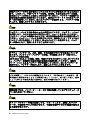
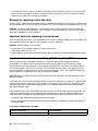
To check the ac power adapter, do the following:
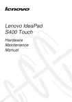
1. Unplug the ac power adapter cable from the computer.
2. Measure the output voltage at the plug of the ac power adapter cable. See the following figure:
3
Pin
Voltage (V dc)
1
+20
2
0
2
1
(20V)
Note: Output voltage of pin no.2 of the ac power adapter may different from the one you are servicing.
3. If the voltage is not correct, replace the ac power adapter.
4. If the voltage is acceptable, do the following:
• Replace the system board.
• If the problem persists, go to Chapter 5 “Lenovo B590” on page 37.
30
Hardware Maintenance Manual
Note: Noise from the ac power adapter does not always indicate a defect.
Checking operational charging
To check whether the battery charges properly during operation, use a discharged battery pack or a battery
pack that has less than 50% of the total power remaining when installed in the computer.
Perform operational charging. If the battery status indicator or icon does not turn on, remove the battery
pack and let it return to room temperature. Reinstall the battery pack. If the charge indicator or icon still does
not turn on, replace the battery pack.
If the charge indicator still does not turn on, replace the system board. Then reinstall the battery pack. If it is
still not charged, go to the next section.
Checking the battery pack
Battery charging does not start until the power meter shows that less than 95% of the total power remains;
under this condition the battery pack can charge to 100% of its capacity. This protects the battery pack from
being overcharged or from having a shortened life.
To check your battery, depending on the operating system you are using, do the following:
• Windows 7: Launch the Power Manager program and click the Battery tab.
• Windows 8:
– Press the recovery button to launch the Lenovo Solution Center program, and then click Battery.
– Open the Lenovo Settings program, and then click Power.
Note: If the battery pack becomes hot, it may not be able to be charged. Remove it from the computer and
leave it at room temperature for a while. After it cools down, reinstall and recharge it.
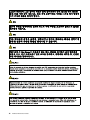
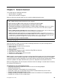
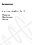
To check the battery pack, do the following:
1. Power off the computer.
2. Remove the battery pack and measure the voltage between battery terminals 1 (+) and 7 (-).
1(+)
2(+)
5
3 4
6(-)
Terminal
Voltage (V dc)
1
+ 0 to + 14
7
Ground (-)
7(-)
3. If the voltage is less than +11.0 V dc, the battery pack has been discharged.
Note: Recharging will take at least 3 hours, even if the indicator does not turn on.
If the voltage is still less than +11.0 V dc after recharging, replace the battery.
4. If the voltage is more than +11.0 V dc, measure the resistance between battery terminals 5 and 7.
The resistance must be 4 to 30 K Ω.
If the resistance is not correct, replace the battery pack. If the resistance is correct, replace the system
board.
Chapter 3. General checkout
31
32
Hardware Maintenance Manual
Chapter 4. Related service information
This chapter presents the following information:
• “Recovering the computer settings” on page 33
• “Passwords” on page 33
• “Power management” on page 34
Recovering the computer settings
This topic provides information about the recovery programs that are available for you to recover the
computer settings.
• Windows 7: The following recovery programs are available on computers with a Windows 7 operating
system:
– OneKey® Recovery Pro
The OneKey Recovery Pro program enables you to back up all your hard disk drive contents, including
the operating system, data files, software programs, and personal settings. You can designate where
the OneKey Recovery Pro program stores the backup. After you have backed up the contents on the
hard disk drive, you can restore the complete contents of the hard disk drive, restore only the desired
files, or restore only the Windows operating system and applications.
– Product Recovery
The Product Recovery program enables you to restore the computer settings to the factory default
settings through recovery media.
Attention: When you use the Product Recovery program to restore the computer settings, all the data
you have stored on the hard disk drive will be deleted and the computer settings will be restored to the
factory default settings. During the restoring process, you will be given the option to save one or more
files currently on the hard disk drive to other media before the data is deleted.
• Windows 8: The preinstalled Windows recovery program enables you to do the following:
– Refreshing the computer without losing personal files
– Restoring the computer to the factory default settings
Attention: When you use the Windows recovery program to restore the computer settings, all the data
you have stored on the hard disk drive will be deleted and the computer will be restored to the factory
default settings. To avoid data loss, back up your data in advance.
– Configuring the advanced startup options
The advanced startup options enable you to do the following:
– Changing the startup settings of the Windows operating system
– Restoring the Windows operating system from a system image
– Starting up from an external device
For more information about the recovery solutions, refer to the help information system of the programs.
Passwords
As many as two passwords might be needed for a Lenovo notebook computer: the power-on password
and the supervisor password.
© Copyright Lenovo 2012
33
If any of these passwords has been set, a prompt for it will be displayed on the screen whenever the
computer is turned on. The computer does not start until the password is entered.
Note: If only a supervisor password is set, the password prompt will not be displayed when the operating
system is started.
Power-on password
A power-on password protects the system from being turned on by an unauthorized person. The password
must be entered before an operating system can be started.
Supervisor password
A supervisor password protects the system information stored in the BIOS. The user must enter the
supervisor password to get access to the BIOS and change the system configuration.
Attention: If you forget the password, there is no service procedure to reset the password. The system
board must be replaced for a scheduled fee.
Power management
Note: Power management modes are not supported for APM operating system.
To reduce power consumption, the computer has three power management modes: screen blank, sleep,
and hibernation.
Screen blank mode
In the following circumstances, the computer goes into screen blank mode:
• The time set on the “Turn off monitor” timer on the Windows 7 operating system expires.
To end screen blank mode and resume normal operation, press any key.
• You have pressed Fn+F2.
To end screen blank mode and resume normal operation, press Fn+F2.
Sleep mode
When the computer enters sleep mode, the following events occur in addition to what occurs in screen
blank mode:
• The LCD is powered off.
• The hard disk drive is powered off.
• The CPU stops.
To enter sleep mode, press Fn+F1.
In certain circumstances, the computer goes into sleep mode automatically:
• If a “suspend time” has been set on the timer, and the user does not do any operation with the keyboard,
the hard disk drive, the parallel connector, or the diskette drive within that time.
• If the battery indicator blinks orange, indicating that the battery power is low.
To cause the computer to return from sleep mode and resume the operation, do one of the following:
• Press the Fn key.
• Open the LCD cover.
• Turn on the power button.
34
Hardware Maintenance Manual
Also, when the time set on the resume timer elapses, the computer automatically returns from sleep mode
and resumes operation.
Note: The computer does not accept any input immediately after it enters sleep mode. Wait a few seconds
before taking any action to reenter operation mode.
Hibernation mode
In hibernation mode, the following occurs:
• The system status, RAM, VRAM, and setup data are stored on the hard disk drive.
• The system is powered off.
If you have defined one of the following actions as the event that causes the system to go into hibernation
mode, perform that action.
• Closing the lid.
• Pressing the power button.
Also, the computer goes into hibernation mode automatically in either of the following conditions:
• If a “hibernation time” has been set on the timer, and if the user does not do any operation with the
keyboard, the hard disk drive, the parallel connector, or the diskette drive within that time.
• If the timer conditions are satisfied in suspend mode.
When the power is turned on, the computer returns from hibernation mode and resumes operation. The
hibernation file in the boot record on the hard disk drive is read, and system status is restored from the
hard disk drive.
Chapter 4. Related service information
35
36
Hardware Maintenance Manual
Chapter 5. Lenovo B590
This chapter presents the following product-specific service references and parts information:
•
“Specifications” on page 37
•
“Status indicators” on page 38
•
“Fn key combinations” on page 39
Specifications
This topic lists the physical features for the Lenovo B590 models.
Processor
• Windows 7: To view the system properties of your computer, click Start, right-click Computer; then
click Properties.
• Windows 8: From the desktop, move the cursor to the top-right or bottom-right corner of the screen to
display the charms. Then click Settings ➙ PC info.
Memory
• Double data rate 3 (DDR3) synchronous dynamic random access memory (SDRAM)
Storage device
• 2.5-inch (7 mm height or 9.5 mm height) hard disk drive
• mSATA solid state drive (on some models for cache only)
Note: If the computer is equipped with both a hard disk drive and an mSATA solid-state drive, do not use the
mSATA solid-state drive as a bootable device. The mSATA solid-state drive is used for “cache” function only.
Display
• Size: 15.6 inches (396 mm)
• Resolution:
– LCD: 1366-by-768
– External monitor: Maximum 2048-by-1536
• Camera
Keyboard
• 6-row Lenovo keyboard
• Recovery button
Interface
• Combo audio jack (stereo headphone or headset)
• USB 2.0 connectors
• USB 3.0 connectors
• RJ45 Ethernet connector
• HDMI connector
© Copyright Lenovo 2012
37
• External monitor connector
• 4-in-1 digital media card reader slot
Optical drive
• 12.7 mm Rambo optical drive (on some models)
Wireless features
• Integrated wireless LAN
• Integrated WiMAX
• 100/1000 Mbps Ethernet communication
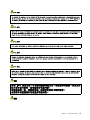
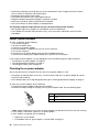
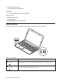
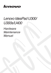
Status indicators
This chapter presents the system status indicators that show the status of the computer.
4
1
2
3
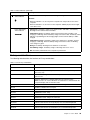
Table 1. Status indicators
Indicator
Meaning
1
Caps Lock status
indicator
White: Caps Lock mode is enabled. You can type all alphabetic characters (A-Z) in
uppercase directly. To enable or disable Caps Lock mode, press the Caps Lock key.
2
Numeric Lock status
indicator
White: The separate numeric keypad on the keyboard is enabled. To enable or disable
the numeric keypad, press the Numeric Lock key.
38
Hardware Maintenance Manual
Table 1. Status indicators (continued)
Indicator
Meaning
3
On: The hard disk drive or optical drive is reading or writing data.
Device access
status indicator
Attention:
• When the indicator is on, do not put the computer into sleep mode or turn off the
computer.
• When the indicator is on, do not move the computer. Sudden physical shock might
cause drive errors.
4
Power and battery
status indicator
• Solid green: The battery charge level is between 80% and 100%, or the battery
discharge level is between 20% and 100%.
• Slow blinking green: The battery charge level is between 20% and 80%, and
charging is continuing. When the battery charge level reaches 80%, the battery status
indicator stops blinking, but the charging might continue until the battery is 100%
charged.
• Slow blinking orange: The battery charge level is between 5% and 20%, and the
charging is continuing. When the battery charge level reaches 20%, the blinking
color changes to green.
• Orange: The battery discharge level is between 5% and 20%.
• Fast blinking orange: The battery charge or discharge level is 5% or less.
• Off: The battery is detached or the computer is powered off.
Fn key combinations
The following table describes the functions of Fn key combinations.
Table 2. Function key combinations
Key combination
Description
Fn+Esc
Enables or disables the camera.
Fn+F1
Puts the computer into sleep mode. To resume normal operation, press
the Fn key only.
Fn+F2
Enables the backlight feature of the computer screen. To disable the feature,
press Fn+F2.
Fn+F3
Switches between the computer display and an external monitor.
Note: You also can use the Windows+P combination to switch between the
computer display and an external monitor.
Fn+F5
Enables or disables the built-in wireless networking features.
Fn+F6
Enables or disables the touch pad.
Fn+F9
Multimedia control: Start/Pause
Fn+F10
Multimedia control: Stop
Fn+F11
Multimedia control: Skip to the previous track
Fn+F12
Multimedia control: Skip to the next track
Fn+Insert
Has the same function as the ScrLk key on a conventional keyboard.
Fn+PrtSc
Has the same function as the SysRq key on a conventional keyboard.
Fn+Home
Has the same function as the Pause key on a conventional keyboard.
Fn+End
Has the same function as the Break key on a conventional keyboard.
Chapter 5. Lenovo B590
39
Table 2. Function key combinations (continued)
Key combination
Description
Fn + up/down arrow
Increases or decreases the display brightness level.
Fn + left/right arrow
Decreases or increases the sound volume.
40
Hardware Maintenance Manual
Chapter 6. FRU replacement notices
This chapter presents notices related to removing and replacing parts. Read this chapter carefully before
replacing any FRU.
CRU statement for customers:
You can resolve some problems with your product with a replacement part you can install yourself, called
a “Customer Replaceable Unit” or “CRU”. Some CRUs are designated as self-service CRUs and others
are designated as optional-service CRUs. Installation of self-service CRUs is your responsibility. For
optional-service CRUs, you can either install the CRU yourself or you can request that a Service Provider
install the CRU according to the warranty service for your product. If you intend on installing the CRU,
Lenovo will ship the CRU to you. CRU information and replacement instructions are shipped with your
product and are available from Lenovo at any time upon request. You can find a list of CRUs for your
product in this Hardware Maintenance Manual. An electronic version of this manual can be found at
http://www.lenovo.com/UserManuals. Follow the on-screen instructions to find the manual for your product.
You might be required to return the defective CRU. When return is required: (1) return instructions, a prepaid
shipping label, and a container will be included with the replacement CRU; and (2) you might be charged for
the replacement CRU if Lenovo does not receive the defective CRU within thirty (30) days of your receipt of
the replacement CRU. See your Lenovo Limited Warranty documentation for full details.
Screw notices
Loose screws can cause a reliability problem. In the Lenovo notebook computer, this problem is addressed
with special nylon-coated screws that have the following characteristics:
• They maintain tight connections.
• They do not easily come loose, even with shock or vibration.
• They are harder to tighten.
Do the following when you service this machine:
•
•
•
•
Keep the screw kit in your tool bag.
It is recommended to use new screws.
It recommended to use each screw only once.
Use a torque screwdriver if you have one.
Tighten screws as follows:
• Plastic to plastic
Turn an additional 90 degrees after the screw head touches the surface of the plastic part:
• Logic card to plastic
Turn an additional 180 degrees after the screw head touches the surface of the logic card:
© Copyright Lenovo 2012
41
• Torque driver
If you have a torque screwdriver, refer to the Torque column in the screw information table for each step.
• Make sure that you use the correct screw. It is recommended to use new screws for replacements. If
you have a torque screwdriver, tighten all screws firmly to the torque specified in the screw information
table for each step.
• Ensure torque screw drivers are calibrated correctly following country specifications.
42
Hardware Maintenance Manual
Chapter 7. Removing and replacing a FRU
This chapter provides instructions on how to remove or replace a FRU.
CRU statement for customers:
You can resolve some problems with your product with a replacement part you can install yourself, called
a “Customer Replaceable Unit” or “CRU”. Some CRUs are designated as self-service CRUs and others
are designated as optional-service CRUs. Installation of self-service CRUs is your responsibility. For
optional-service CRUs, you can either install the CRU yourself or you can request that a Service Provider
install the CRU according to the warranty service for your product. If you intend on installing the CRU,
Lenovo will ship the CRU to you. CRU information and replacement instructions are shipped with your
product and are available from Lenovo at any time upon request. You can find a list of CRUs for your
product in this Hardware Maintenance Manual. An electronic version of this manual can be found at
http://www.lenovo.com/UserManuals. Follow the on-screen instructions to find the manual for your product.
You might be required to return the defective CRU. When return is required: (1) return instructions, a prepaid
shipping label, and a container will be included with the replacement CRU; and (2) you might be charged for
the replacement CRU if Lenovo does not receive the defective CRU within thirty (30) days of your receipt of
the replacement CRU. See your Lenovo Limited Warranty documentation for full details.
General guidelines
This chapter presents directions and drawings for use in removing and replacing a FRU. Be sure to observe
the following general rules:
1. Do not try to service any computer unless you have been trained and certified. An untrained person runs
the risk of damaging parts.
2. Before replacing any FRU, review Chapter 6 “FRU replacement notices” on page 41.
3. Begin by removing any FRUs that have to be removed before replacing the failing FRU. Such FRUs are
listed in each FRU replacement section. Remove them in the order in which they are listed.
4. Follow the correct sequence in the steps for removing a FRU, as given in the drawings by the numbers
in square callouts.
5. When turning a screw, turn it in the direction as given by the arrow in the drawing.
6. When removing a FRU, move it in the direction as given by the arrow in the drawing.
7. To put the new FRU in place, reverse the removal procedure and follow any notes that pertain to
replacement.
8. When replacing a FRU, use the correct screw(s) as shown in the procedures.
DANGER
Before removing any FRU, turn off the computer, unplug all power cords from electrical outlets,
remove the battery pack, and then disconnect any interconnecting cables.
Attention: After replacing a FRU, do not turn on the computer until you have made sure that all screws,
springs, and other small parts are in place and none are loose inside the computer. Verify this by shaking
the computer gently and listening for rattling sounds. Metallic parts or metal flakes can cause electrical
short circuits.
Attention: The system board is sensitive to, and can be damaged by, electrostatic discharge. Before
touching it, establish personal grounding by touching a ground point with one hand or by using an
electrostatic discharge (ESD) strap (P/N 6405959).
© Copyright Lenovo 2012
43
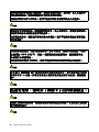
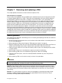
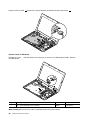
1010 Battery pack
Removal steps of battery pack
DANGER
Use only the battery specified in the parts list for your computer. Any other battery could ignite
or explode.
Unlock the spring-loaded battery latch 1 . Holding the manual battery latch in the unlocked position, remove
the battery pack in the direction shown by the arrow 2 .
1
2
2
When installing: Install the battery pack in the slot. Make sure that the battery latches are in the locked
position.
1020 Bottom slot cover
For access, remove this FRU:
• “1010 Battery pack” on page 44
44
Hardware Maintenance Manual
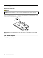
Removal steps of bottom slot cover
Remove the screws 1 , and then remove the cover 2 .
1
1
2
2
Step
Screw (quantity)
Color
Torque
1
M2 × 3 mm, flat-head, nylon-coated (2)
Black
1.85 kgf-cm
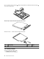
1030 Optical drive
For access, remove these FRUs in order:
• “1010 Battery pack” on page 44
• “1020 Bottom slot cover” on page 44
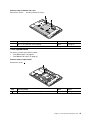
Removal steps of optical drive
Remove the screw 1 .
1
Step
Screw (quantity)
Color
Torque
1
M2 × 3 mm, flat-head, nylon-coated (1)
Black
1.85 kgf-cm
Chapter 7. Removing and replacing a FRU
45
Insert a screwdriver into the screw hole 2 and push the optical drive in the direction shown by the arrow 3 .
Then remove the optical drive.
3
2
Removal steps of optical drive bezel and optical drive bracket
Remove the screws 1 and then remove the optical drive bracket.
1
2
Step
Screw (quantity)
Color
Torque
1
M2 × 3 mm, flat-head, nylon-coated (2)
Black
1.85 kgf-cm
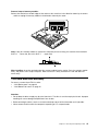
1040 Memory modules
For access, remove these FRUs in order:
• “1010 Battery pack” on page 44
• “1020 Bottom slot cover” on page 44
46
Hardware Maintenance Manual
Removal steps of memory modules
Release the two latches on both edges of the socket at the same time in the direction shown by the arrows
1 , and then unplug the memory module in the direction shown by the arrow 2 .
1
1
2
Note: If only one memory module is used on the computer you are servicing, the card must be installed in
SLOT-0 ( a : lower slot), but not in SLOT-1 ( b : upper slot).
b
a
When installing: Insert the notched end of the memory module into the socket. Press the memory module
firmly, and pivot it until it snaps into place. Make sure that it is firmly installed in the slot and does not
move easily.
1050 Hard disk drive assembly
For access, remove these FRUs in order:
• “1010 Battery pack” on page 44
• “1020 Bottom slot cover” on page 44
Attention:
• Do not drop the drive or apply any physical shock to it. The drive is sensitive to physical shock. Improper
handling can cause damage and permanent loss of data.
• Before removing the drive, have the user make a backup copy of all the information on it if possible.
• Never remove the drive while the computer is operating or is in suspend mode.
Chapter 7. Removing and replacing a FRU
47
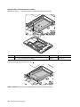
Removal steps of hard disk drive assembly
Remove the screw 1 , then pull the tab in the direction shown by the arrow 2 .
1
2
Step
Screw (quantity)
Color
Torque
1
M2 × 3 mm, flat-head, nylon-coated (1)
Black
1.85 kgf-cm
Remove the hard disk drive from the slot 3 .
3
When installing: Ensure that the hard disk drive connector is attached firmly.
48
Hardware Maintenance Manual
Removal steps of hard disk drive bracket
Remove the screws 1 .
1
1
1
1
Step
Screw (quantity)
Color
Torque
1
M3 × 4 mm, flat-head, nylon-coated (4)
Silver
4 kgf-cm
Remove the hard disk drive bracket as shown by the arrow 2 .
2
1060 PCI Express Mini Card for wireless LAN
For access, remove these FRUs in order:
• “1010 Battery pack” on page 44
• “1020 Bottom slot cover” on page 44
Chapter 7. Removing and replacing a FRU
49
Removal steps of PCI Express Mini Card for wireless LAN
In steps 1 , disconnect the cables from the card using the removal tool antenna RF connector (P/N: 08K7159)
or pick up the cables with your fingers and then gently disconnecting the cable from the card in the direction
of the arrows. Then remove the screw 2 .
1
1
2
Step
Screw (quantity)
Color
Torque
2
M2 × 3 mm, flat-head, nylon-coated (1)
Black
1.85 kgf-cm
Remove the card in the direction shown by the arrow 3 .
3
When installing: Plug the black cable (MAIN) into the jack labeled M, and the white cable (AUX) into the jack
labeled A on the card.
50
Hardware Maintenance Manual
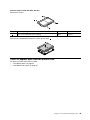
1070 mSATA solid state drive
For access, remove these FRUs in order:
• “1010 Battery pack” on page 44
• “1020 Bottom slot cover” on page 44
Attention:
• Do not drop the drive or apply any physical shock to it. The drive is sensitive to physical shock. Improper
handling can cause damage and permanent loss of data.
• Before removing the drive, have the user make a backup copy of all the information on it if possible.
• Never remove the drive while the computer is operating or is in suspend mode.
Removal steps of mSATA solid state drive
Remove the screw 1 .
1
Step
Screw (quantity)
Color
Torque
1
M2 × 3 mm, flat-head, nylon-coated (1)
Black
1.85 kgf-cm
Chapter 7. Removing and replacing a FRU
51
Remove the mSATA solid state drive 2 .
2
1080 Backup battery
For access, remove these FRUs in order:
• “1010 Battery pack” on page 44
• “1020 Bottom slot cover” on page 44
Removal steps of backup battery
DANGER
Use only the battery specified in the parts list for your computer. Any other battery could ignite
or explode.
52
Hardware Maintenance Manual
Insert a screwdriver into the backup battery hole and push the backup battery until the battery pops up.
When installing: Ensure that the connector is attached firmly.
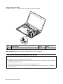
1090 Keyboard
For access, remove these FRUs in order:
• “1010 Battery pack” on page 44
• “1020 Bottom slot cover” on page 44
Chapter 7. Removing and replacing a FRU
53
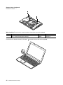
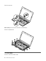
Removal steps of keyboard
Remove the screws 1 .
1
1
1
When installing: Ensure that the screws have been fastened to secure the keyboard.
Step
Screw (quantity)
Color
Torque
1
M2.5 × 8 mm, flat-head, nylon-coated (3)
Black
4.0 kgf-cm
Push hard in the direction shown by the arrow 2 to unlatch the front side of the keyboard.
2
54
Hardware Maintenance Manual
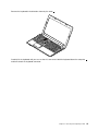
Remove the keyboard in the direction shown by the arrow 3 .
3
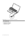
Carefully lift the keyboard until you can see how it’s connected. Hold the keyboard above the computer 4 ,
and then detach the keyboard connector.
Chapter 7. Removing and replacing a FRU
55
4
6
5
When installing: Ensure that the keyboard connector is attached firmly.
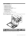
1100 Keyboard bezel
For access, remove these FRUs in order:
• “1010 Battery pack” on page 44
• “1020 Bottom slot cover” on page 44
• “1030 Optical drive” on page 45
• “1090 Keyboard” on page 53
56
Hardware Maintenance Manual
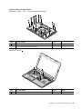
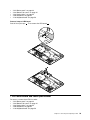
Removal steps of keyboard bezel
Remove the screws 1 and 2 that secure the keyboard bezel.
2
2
1
1
2
1
1
1
1
1
1
1
1
Step
Screw (quantity)
Color
Torque
1
M2.5 × 8 mm, flat-head, nylon-coated (10)
Black
4.0 kgfcm
2
M2 × 3 mm, flat-head, nylon-coated (3)
Black
1.85 kgf-cm
Remove the screws 3 .
3
3
3
Step
Screw (quantity)
Color
Torque
3
M2 × 5 mm, flat-head, nylon-coated (3)
Black
1.85 kgf-cm
Chapter 7. Removing and replacing a FRU
57
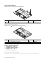
Detach the connectors.
5
4
8
9
6
7
When installing: Ensure that all the connectors are attached firmly.
Remove the keyboard bezel.
10
10
10
11
10
10
10
10
10
10
1110 LED board
For access, remove these FRUs in order:
58
Hardware Maintenance Manual
•
•
•
•
•
“1010
“1020
“1030
“1090
“1100
Battery pack” on page 44
Bottom slot cover” on page 44
Optical drive” on page 45
Keyboard” on page 53
Keyboard bezel” on page 56
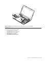
Removal steps of LED board
Peel off the mylar tape 1 . Then remove the LED board 2 .
1
2
1120 Power board and touch pad bracket
For access, remove these FRUs in order:
• “1010 Battery pack” on page 44
• “1020 Bottom slot cover” on page 44
• “1030 Optical drive” on page 45
• “1090 Keyboard” on page 53
• “1100 Keyboard bezel” on page 56
Chapter 7. Removing and replacing a FRU
59
Removal steps of power board
Remove the screw 1 and then remove the power board 2 .
2
1
Step
Screw (quantity)
Color
Torque
1
M2 × 3 mm, flat-head, nylon-coated (1)
Black
1.85 kgf-cm
Removal steps of touch pad bracket
Remove the screw 1 and then remove the touch pad bracket 2 .
2
1
Step
Screw (quantity)
Color
Torque
1
M2 × 3 mm, flat-head, nylon-coated (1)
Black
1.85 kgf-cm
1130 Microphone assembly
For access, remove these FRUs in order:
• “1010 Battery pack” on page 44
• “1020 Bottom slot cover” on page 44
• “1030 Optical drive” on page 45
• “1090 Keyboard” on page 53
• “1100 Keyboard bezel” on page 56
Removal steps of microphone assembly
Detach the connector 1 , and then remove the microphone assembly in the direction shown by the arrow 2 .
60
Hardware Maintenance Manual
When installing: Ensure that the connector is attached firmly to the system board.
1140 I/O board
For access, remove these FRUs in order:
• “1010 Battery pack” on page 44
• “1020 Bottom slot cover” on page 44
• “1030 Optical drive” on page 45
• “1090 Keyboard” on page 53
• “1100 Keyboard bezel” on page 56
Chapter 7. Removing and replacing a FRU
61
Removal steps of I/O board
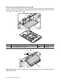
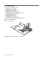
Remove the screws 1 , and then detach the cable. Remove the I/O board 4 .
1
1
4
2
3
Step
Screw (quantity)
Color
Torque
1
M2 × 5 mm, flat-head, nylon-coated (2)
Black
1.85 kgf-cm
When installing: Ensure that the cable is attached firmly to the system board.
1150 System board assembly and USB board
Important notices for handling the system board:
When handling the system board, bear the following in mind:
• Be careful not to drop the system board on a bench top that has a hard surface, such as metal, wood, or composite.
• Avoid rough handling of any kind.
• At every point in the process, be sure not to drop or stack the system board.
• If you put a system board down, be sure to put it only on a padded surface such as an ESD mat or a corrugated
conductive surface.
62
Hardware Maintenance Manual
For access, remove these FRUs in order:
• “1010 Battery pack” on page 44
• “1020 Bottom slot cover” on page 44
• “1030 Optical drive” on page 45
• “1040 Memory modules” on page 46
• “1050 Hard disk drive assembly” on page 47
• “1060 PCI Express Mini Card for wireless LAN” on page 49
• “1070 mSATA solid state drive” on page 51
• “1080 Backup battery” on page 52
• “1090 Keyboard” on page 53
• “1100 Keyboard bezel” on page 56
• “1130 Microphone assembly” on page 60
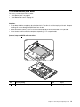
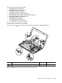
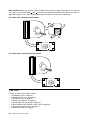
Removal steps of system board assembly
Remove the screws 1 , and then detach the connectors as shown in the following illustration.
2
3
1
1
5
4
6
1
7
10
8
9
Step
Screw (quantity)
Color
Torque
1
M2 × 5 mm, flat-head, nylon-coated (2)
Black
1.85 kgf-cm
When installing: Ensure that all the connectors are attached firmly.
Chapter 7. Removing and replacing a FRU
63
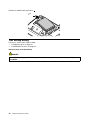
Detach the DC-in cable 11 . Remove the system board in the direction shown by the arrow 12 .
11
12
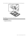
Removal steps of USB board
Remove the screw 1 , and then detach the connectors as shown in the following illustration. Remove
the USB board 4 .
3
2
1
4
Step
Screw (quantity)
Color
Torque
1
M2 × 5 mm, flat-head, nylon-coated (1)
Black
1.85 kgf-cm
When installing: Ensure that the cable is attached firmly to the system board.
64
Hardware Maintenance Manual
1160 DC-in connector
For access, remove these FRUs in order:
• “1010 Battery pack” on page 44
• “1020 Bottom slot cover” on page 44
• “1030 Optical drive” on page 45
• “1040 Memory modules” on page 46
• “1050 Hard disk drive assembly” on page 47
• “1060 PCI Express Mini Card for wireless LAN” on page 49
• “1070 mSATA solid state drive” on page 51
• “1080 Backup battery” on page 52
• “1090 Keyboard” on page 53
• “1100 Keyboard bezel” on page 56
• “1130 Microphone assembly” on page 60
• “1140 I/O board” on page 61
• “1150 System board assembly and USB board” on page 62
Removal steps of DC-in connector
Detach the connector 1 . Remove the screw 2 and the DC-in connector bracket 3 . Then remove the DC-in
connector in the direction shown by the arrow 4 .
2
3
1
4
4
Step
Screw (quantity)
Color
Torque
2
M2.5 × 5 mm, flat-head, nylon-coated (1)
Black
4 kgf-cm
When installing: Ensure that the cable is attached firmly to the system board.
Chapter 7. Removing and replacing a FRU
65
1170 Thermal module
For access, remove these FRUs in order:
• “1010 Battery pack” on page 44
• “1020 Bottom slot cover” on page 44
• “1030 Optical drive” on page 45
• “1040 Memory modules” on page 46
• “1050 Hard disk drive assembly” on page 47
• “1060 PCI Express Mini Card for wireless LAN” on page 49
• “1070 mSATA solid state drive” on page 51
• “1080 Backup battery” on page 52
• “1090 Keyboard” on page 53
• “1100 Keyboard bezel” on page 56
• “1130 Microphone assembly” on page 60
• “1150 System board assembly and USB board” on page 62
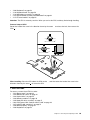
Removal steps of thermal module
Detach the fan connector 1 .
1
When installing: Ensure that the connector is attached firmly.
66
Hardware Maintenance Manual
Loosen the screws 2 to 8 .
Note: Different models might have different numbers of screws.
7
8
6
5
2
4
3
Lift the fan assembly in the direction shown by the arrow 9 .
Note: Be careful not to damage the connector.
9
Chapter 7. Removing and replacing a FRU
67
When installing: Before you attach the thermal module to the computer, apply thermal grease, at an amount
of 0.2 grams, on the part marked a and b as shown in the following illustration. Either too much or too less
application of grease can cause a thermal problem due to imperfect contact with a component.
For models with a discrete thermal module
a
b
For models with an integrated thermal module
a
1180 CPU
For access, remove these FRUs in order:
• “1010 Battery pack” on page 44
• “1020 Bottom slot cover” on page 44
• “1030 Optical drive” on page 45
• “1040 Memory modules” on page 46
• “1050 Hard disk drive assembly” on page 47
• “1060 PCI Express Mini Card for wireless LAN” on page 49
• “1070 mSATA solid state drive” on page 51
• “1080 Backup battery” on page 52
68
Hardware Maintenance Manual
•
•
•
•
•
“1090 Keyboard” on page 53
“1100 Keyboard bezel” on page 56
“1130 Microphone assembly” on page 60
“1150 System board assembly and USB board” on page 62
“1170 Thermal module” on page 66
Attention: The CPU is extremely sensitive. When you service the CPU, avoid any kind of rough handling.
Removal steps of CPU
Rotate the head of the screw in the direction shown by the arrow 1 to release the lock, then remove the
CPU 2 .
1
b
a
2
When installing: Place the CPU above the CPU socket a , and then rotate the head of the screw in the
direction shown by the arrow b to secure the CPU.
1190 LCD unit
For access, remove these FRUs in order:
• “1010 Battery pack” on page 44
• “1020 Bottom slot cover” on page 44
• “1030 Optical drive” on page 45
• “1040 Memory modules” on page 46
• “1050 Hard disk drive assembly” on page 47
• “1060 PCI Express Mini Card for wireless LAN” on page 49
• “1070 mSATA solid state drive” on page 51
• “1080 Backup battery” on page 52
• “1090 Keyboard” on page 53
Chapter 7. Removing and replacing a FRU
69
•
•
•
•
•
“1100 Keyboard bezel” on page 56
“1130 Microphone assembly” on page 60
“1140 I/O board” on page 61
“1150 System board assembly and USB board” on page 62
“1160 DC-in connector” on page 65
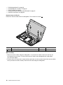
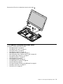
Removal steps of LCD unit
Release the antenna cables from the cable guides. Then remove the screws 1 .
1
1
1
1
Step
Screw (quantity)
Color
Torque
1
M2.5 × 5 mm, flat-head, nylon-coated (4)
Black
4 kgf-cm
When installing:
• Route the antenna cables along the cable guides. As you route the cables, make sure that they are
not subjected to any tension. Tension could cause the cables to be damaged by the cable guides,
or a wire to be broken.
• Ensure that the LCD connector is attached firmly and make sure that you do not pinch the antenna cables
when you attach the LCD assembly. Route the LCD cable along the cable guides.
70
Hardware Maintenance Manual
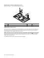
Remove the LCD unit in the direction shown by the arrow 2 .
2
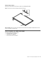
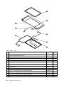
1210 Speaker assembly and base cover
For access, remove these FRUs in order:
• “1010 Battery pack” on page 44
• “1020 Bottom slot cover” on page 44
• “1030 Optical drive” on page 45
• “1040 Memory modules” on page 46
• “1050 Hard disk drive assembly” on page 47
• “1060 PCI Express Mini Card for wireless LAN” on page 49
• “1070 mSATA solid state drive” on page 51
• “1080 Backup battery” on page 52
• “1090 Keyboard” on page 53
• “1100 Keyboard bezel” on page 56
• “1130 Microphone assembly” on page 60
• “1140 I/O board” on page 61
• “1150 System board assembly and USB board” on page 62
• “1160 DC-in connector” on page 65
• “1190 LCD unit” on page 69
Chapter 7. Removing and replacing a FRU
71
Removal steps of speaker assembly and base cover
Remove the screws 1 . Then remove the speaker assembly 2 .
1
1
2
1
1
2
Step
Screw (quantity)
Color
Torque
1
M2.5 × 5.7 mm, flat-head, nylon-coated (4)
Black
4.0 kgf-cm
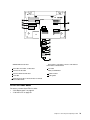
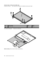
Applying labels to the base cover
The new base cover is shipped with a kit containing labels of several kinds. Apply those labels listed when
you replace the base cover. For the labels which are not shipped with the new base cover, peel them off
from the old base cover, and adhere them to the new one.
Note: If you replace a part with the Windows Certificate of Authentication (COA) label 11 , return the old part
with the label attached to the customer. Otherwise, you can provide the customer with a letter, stating the
original location of the label on the computer and the information on the label, such as the part number,
serial number, and product key.
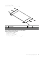
The following illustration shows the correct location of each label.
72
Hardware Maintenance Manual
13
12
1
11
10
2
3
4
5
6
7
8
9
1 WWAN IMEI barcode label
7 Brazil wireless LAN label or wireless LAN label for
United States/Canada/Taiwan
2 China label, KCC label, or MAC label
8 PPT label
3 Indonesia D side label
9 Malaysia SIRIM label
4 Indonesia WLAN and BT label
10 Vodafone label
5 Israel label
12 Rating label
6 Brazil Bluetooth label / Bluetooth label for United
States/Canada/Taiwan
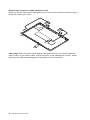
2010 LCD front bezel
For access, remove these FRUs in order:
• “1010 Battery pack” on page 44
• “1190 LCD unit” on page 69
Chapter 7. Removing and replacing a FRU
73
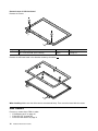
Removal steps of LCD front bezel
Remove the screws 1 .
1
1
Step
Screw (quantity)
Color
Torque
1
M2 × 5 mm, flat-head, nylon-coated (2)
Black
1.85 kgf-cm
Remove the LCD front bezel in the direction shown by the arrows 2 .
2
2
2
2
When installing: Make sure that all the latches are attached firmly. Then secure the bezel with the screws.
2020 Camera
For access, remove these FRUs in order:
• “1010 Battery pack” on page 44
• “1190 LCD unit” on page 69
• “2010 LCD front bezel” on page 73
74
Hardware Maintenance Manual
Removal steps of camera
Remove the camera from the LCD cover as shown in the following illustration.
Note: The camera is stuck on the top center of the LCD cover.
1
2
When installing: Stick the camera to the top center of the LCD cover and adjust the placement to ensure
that the connector is attached firmly.
2030 LCD panel, LCD cable, and hinges
For access, remove these FRUs in order:
• “1010 Battery pack” on page 44
• “1190 LCD unit” on page 69
• “2010 LCD front bezel” on page 73
Chapter 7. Removing and replacing a FRU
75
Removal steps of LCD panel and LCD cable
Remove the screws 1 . Then remove the LCD panel in the direction shown by the arrow 2 .
1
1
1
2
1
1
1
Step
Screw (quantity)
Color
Torque
1
M2 × 5 mm, flat-head, nylon-coated (6)
Black
1.85 kgf-cm
Turn over the LCD panel 3 . Remove the LCD cable.
5
4
When installing: Ensure that the cable is attached firmly.
76
Hardware Maintenance Manual
3
Removal steps of hinges
Remove the screws 1 . Then remove the hinges 2 .
1
2
1
1
2
1
Step
Screw (quantity)
Color
Torque
1
M2 × 3 mm, flat-head, nylon-coated (4)
Black
1.85 kgf-cm
2040 Antenna assembly and LCD rear cover
For access, remove these FRUs in order:
• “1010 Battery pack” on page 44
• “1190 LCD unit” on page 69
• “2010 LCD front bezel” on page 73
• “2020 Camera” on page 74
• “2030 LCD panel, LCD cable, and hinges” on page 75
Chapter 7. Removing and replacing a FRU
77
Removal steps of antenna assembly and LCD rear cover
Release the antenna cables from the cable guides of the LCD rear cover assembly and from the hinges in
the direction shown by the arrows 1 .
1
1
Cable routing: Route the antenna cables along the cable guides and secure the antenna boards with
adhesive tapes. As you route the cables, make sure that they are not subjected to any tension. Tension
could cause the cables to be damaged by the cable guides, or a wire to be broken.
78
Hardware Maintenance Manual
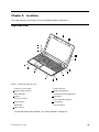
Chapter 8. Locations
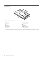
This chapter presents the locations of the Lenovo B590 hardware components.
Right-side view
2
1
2
4
15
14
3
4
13
12
5
11
6
7
10
9
8
Figure 1. Lenovo B590 right-side view
1 Camera (on some models)
9 Combo audio jack
2 Wireless module antennas
10 Media card reader slot
3 Status indicators1
11 Touch pad and touch pad buttons
4 Speakers
12 Microphone
5 ac power connector
13 Power and battery indicator1
6 USB connector
14 Power button
7 Optical drive
15 Recovery button
8 USB connector
1
For the description of the indicators, see “Status indicators” on page 38.
© Copyright Lenovo 2012
79
Bottom view
1
2
3
4
5
10
8
7
6
9
Figure 2. Lenovo B590 bottom view
1 Battery lock
6 Monitor connector
2 Battery pack
7 Ethernet connector
3 Battery latch
8 HDMI port
4 Security keyhole
9 USB 3.0 connector
5 Fan louvers
10 Bottom slot cover1
1
80
The memory modules, hard disk drive, and wireless cards are located underneath the bottom slot cover.
Hardware Maintenance Manual
Chapter 9. Parts list
This chapter contains following lists of the service parts.
• “Overall” on page 82
• “LCD FRUs” on page 85
• “Keyboard” on page 87
• “Miscellaneous parts” on page 89
• “ac power adapters” on page 90
• “Power cords” on page 91
Notes:
• Each FRU is available for all types or models, unless otherwise specified.
• A CRU is identified by a single asterisk (*) or two asterisks (**) in the CRU ID column. An N in the CRU ID column
means that the part is not a CRU. A single asterisk (*) means that the part is a self-service CRU; two asterisks
(**) means that the part is an optional-service CRU.
CRU statement for customers:
You can resolve some problems with your product with a replacement part you can install yourself, called a
“Customer Replaceable Unit” or “CRU”. Some CRUs are designated as self-service CRUs and others are
designated as optional-service CRUs. Installation of self-service CRUs is your responsibility. For optional-service
CRUs, you can either install the CRU yourself or you can request that a Service Provider install the CRU according
to the warranty service for your product. If you intend on installing the CRU, Lenovo will ship the CRU to you. CRU
information and replacement instructions are shipped with your product and are available from Lenovo at any time
upon request. You can find a list of CRUs for your product in this Hardware Maintenance Manual. An electronic
version of this manual can be found at http://www.lenovo.com/UserManuals. Follow the on-screen instructions to
find the manual for your product. You might be required to return the defective CRU. When return is required: (1)
return instructions, a prepaid shipping label, and a container will be included with the replacement CRU; and (2) you
might be charged for the replacement CRU if Lenovo does not receive the defective CRU within thirty (30) days of
your receipt of the replacement CRU. See your Lenovo Limited Warranty documentation for full details.
Lenovo computers contain the following types of CRUs:
– Self-service CRUs: These CRUs unplug or are held by no more than two screws. Examples of these types
of CRUs include the ac power adapter, power cord, battery, and hard disk drive. Other self-service CRUs
depending on product design might include the memory module, wireless card, keyboard, and palm rest
with finger print reader and touch pad.
– Optional-service CRUs: These CRUs are isolated parts within the computer that are concealed by an access
panel that is typically secured by more than two screws. Once the access panel is removed, the specific
CRU is visible.
© Copyright Lenovo 2012
81
Overall
1
22
h
2
a
g
3
21
4
20
19
b
5
18
6
17
16
7
c
15
8
14
9
d
f
10
e
13
11
12
Table 3. Parts list—Overall
No. FRU (Overall)
FRU no.
CRU
ID
1
LCD unit (see “LCD FRUs” on page 85.)
2
LB59A Power Board
90001037
N
3
LB58 LED Board W/Cable
90200814
N
82
Hardware Maintenance Manual
Table 3. Parts list—Overall (continued)
No. FRU (Overall)
FRU no.
CRU
ID
4
LB59A Upper Case WO/FP
90201912
N
5
LB59A USB Board
90001035
N
6
LB58 Speaker R
90200832
N
7
Battery, 6CELL 2.2Ah, 48Wh, Sanyo
121500047 *
7
Battery, 6CELL 2.2Ah, 48Wh, Sony
121500048 *
7
Battery, 6CELL 2.2Ah, 48Wh, LG
121500049 *
7
Battery, 6CELL 2.2Ah, 48Wh, SMP
121500050 *
7
Battery, 6CELL 2.8Ah, L11L6F01 3S2P 62Wh Batt C01 Origa, LG
121500052 *
7
Battery, 6CELL 2.8Ah, SM/S L11M6F01 3S2P 62Wh Batt C01 Origa, SMP
121500053 *
8
LB58 DC-IN Cable
90200811
N
9
LB58 Lower Case
90200822
N
10
ODD, 12.7mm Tray-in Rambo, PLDS, DS-8A8SH
25201487
*
10
ODD, 12.7mm Tray-in Rambo, Sony Optiarc, AD-7740H
25201106
*
10
ODD, 12.7mm Tray-in Rambo, TSST, SN-208AB
25201108
*
10
ODD, 12.7mm Tray-in Rambo, HLDS, GT50N
25201635
*
11
LB58 IO Board
90000234
N
12
LB59A Memory Door
90201905
N
13
HDD, 320GB 5400rpm,, MN500S WD3200LPVT-08G33T1
16200265
**
13
HDD, 320GB 5400rpm, Toshiba Capricorn BS (H6sp),Toshiba MK3265GSX 5400RPM 320G
16200097
**
13
HDD, 320GB 5400rpm, HGST Jaquar B7, HGST HTS545032A7E380 5400PRM7mm 320G
16200068
**
13
HDD, 320GB 5400rpm, Seagate Sapta 15, Seagate ST320LT020 5400RPM 7MM 320G
16005211
**
13
HDD, 500GB 5400rpm, WD ML500M, WD5000BPVT-08A1Y
16200118
**
13
HDD, 500GB 5400rpm, WD ML375M, WD5000BPVT-08HXZ
16200090
**
13
HDD, 500GB 5400rpm,, MN500S WD5000LPVT-08G33T1
16200264
**
13
HDD, 500GB 5400rpm, Toshiba Capricorn BS (H6sp), Toshiba MK5065GSX 5400RPM 500G
16200098
**
13
HDD, 500GB 5400rpm, HGST HTS545050A7E380 5400PRM7mm
16200067
**
13
HDD, 500GB 5400rpm, HTS547550A9E384 9.5mm Jet B
16200006
**
13
HDD, 500GB 5400rpm, ST500LM012 M8
16200210
**
13
HDD, 500GB 5400rpm, Yarra (1D) ST500LT012
16200211
**
13
HDD, 750GB 5400rpm, WD ML500M, WD7500BPVT-08A1Y
16200119
**
13
HDD, 750GB 5400rpm, WD ML375M, WD7500BPVT-08HXZ
16200121
**
13
HDD, 750GB 5400rpm, HGST Jaguar B, HTS541075A9E680
16200192
**
13
HDD, 750GB 5400rpm, ST750LM022 M8
16200209
**
13
HDD, 1TB 5400rpm, WD ML500M, WD10JPVT-08A1Y
16200120
**
13
HDD, 1TB 5400rpm, HGST Jaquar B, HTS541010A9E680
16200193
**
13
HDD, 1TB 5400rpm, ST1000LM024
16200208
**
Chapter 9. Parts list
83
Table 3. Parts list—Overall (continued)
No. FRU (Overall)
FRU no.
CRU
ID
13
HDD, 320GB 7200rpm, WD MX320S-1, WD3200BEKT-08PVM
16200092
**
13
HDD, 320GB 7200rpm, Toshiba Capricorn CS (H6sp), TSB MK3261GSY 7200PRM 9.5mm
320G HDD
16200099
**
13
HDD, 320GB 7200rpm, HGST Jaquar C7, HTS725032A7E630
16200194
**
13
HDD, 320GB 7200rpm, Seagate Julius 1 4K, Seagate ST320LT007 7200RPM 7MM 320G
16005030
**
13
HDD, 500GB 7200rpm, WD MX375M, WD5000BPKT-08PK4T
16200124
**
13
HDD, 500GB 7200rpm, Toshiba Capricorn CS (H6sp), TSB MK5061GSY 7200PRM 9.5mm
500G HDD
16200100
**
13
HDD, 500GB 7200rpm, Jaguar C7, HTS725050A7E630
16200195
**
14
LB58 Microphone
90200829
N
15
LB58 Speaker L
90200833
N
16
SSD, mSATA 16G, Sandisk, U100 mSATA SDSA5DK-016G
16200215
N
16
MZMPA016HMCD-000L1
16200255
N
17
WLAN, Non-Intel 1x1 11bgn + BT4.0 Combo, Broadcom 4313 + 20702
20200100
20200101
*
17
WLAN, Non-Intel 2x2 11abgn + BT4.0 Combo, Broadcom 43228 + 20702
20200098
20200099
*
17
WLAN, Intel 2x2 11bgn + BT4.0 Combo, Jackson Peak 1
20200078
*
17
WLAN, Non-Intel 1x1 11bgn, Broadcom BCM4313 1*1 BGN MOW
20200102
*
17
WLAN, Non-Intel 1x1 11bgn, Realtek bgn 1x1 HMC WLAN Stockton
20200016
*
18
Memory Module, DDRIII 1600 2GB, Samsung, M471B5773DH0-CK0 DDR3 1600 2GB
11200340
*
18
Memory Module, DDRIII 1600 2GB, Hynix, HMT325S6CFR8C-PB DDR3 1600 2GB
11200343
*
18
Memory Module, DDRIII 1600 2GB, Micron, MT8KTF25664HZ-1G6M1 DDR3 1600 2GB
11200346
*
18
Memory Module, DDRIII 1600 2GB, Memory Moduleaxel, RMT3150ED58E8W-1600 DDR3
1600 2GB
11200392
*
18
Memory Module, DDRIII 1600 2GB, Sharetronic(Micron), SM321NH08IAF DDR3 1600 2GB
11200396
*
18
Memory Module, DDRIII 1600 4GB, Samsung, M471B5273DH0-CK0 DDR3 1600 4GB
11200341
*
18
Memory Module, DDRIII 1600 4GB, Hynix, HMT351S6CFR8C-PB DDR3 1600 4GB
11200344
*
18
Memory Module, DDRIII 1600 4GB, Micron, MT16KTF51264HZ-1G6M1 DDR3 1600 4GB
11200347
*
18
Memory Module, DDRIII 1600 4GB, Ramaxel, RMT3160ED58E9W-1600 DDR3 1600 4GB
11200393
*
18
Memory Module, DDRIII 1600 4GB, Sharetronic(Micron), SM322NQ08IAF DDR3 1600 4GB
11200397
*
19
LB59A MB W8 UMA WO/SBA
90001836
N
19
LB59A MB W8P UMA WO/SBA
90001837
N
19
LB59A MB W8 DIS N13M-GE1 1G WO/SBA
90001838
N
19
LB59A MB W8P DIS N13M-GE1 1G WO/SBA
90001839
N
19
LB59B MB W8 UMA WO/SBA
90001840
N
19
LB59B MB W8P UMA WO/SBA
90001841
N
19
LB59B MB W8 DIS N13M-GE1 1G W/SBA
90001842
N
19
LB59B MB W8P DIS N13M-GE1 1G W/SBA
90001843
N
84
Hardware Maintenance Manual
Table 3. Parts list—Overall (continued)
No. FRU (Overall)
FRU no.
20
CPU, Intel I5-2520M 2.5G 3M 2c J1 PGA processor
102001067 N
20
CPU, Intel B815 1.6G Q0 2M 2cPGA processor
102500229 N
20
CPU, Intel I3-2370M 2.4G J1 3M 2cPGA processor
102500228 N
20
CPU, Intel SNB I3-2350M 2.3G 3M J1 PGA processor
102500018 N
20
CPU, Intel SNB I3-2330M 2.2G 3M J1 PGA processor
102500017 N
20
CPU, Intel SNB B950 2.1G 2M Q0 PGA processor
102500016 N
20
CPU, Intel SNB B940 2.0G 2M Q0 PGA processor
102500015 N
20
CPU, Intel SNB I3-2310M 2.1G 3M 2c J1 PGA processor
102001065 N
20
CPU, Intel B970 2.3G D2 2M 2cPGA processor
102500230 N
20
CPU, Intel SNB B800 1.5G Q0 2M 2c PGA processor
102500101 N
20
CPU, Intel SNB B960 2.2G 2M 35W PGA processor
102500133 N
20
CPU, Intel B820 1.7G Q0 2M 2cPGA processor
102500350 N
20
CPU, i5-3210M Ivy Bridge L-0 3MB 2c PGA 2.5GHz STD 35W processor
102500301 N
20
CPU, i3-3110M Ivy Bridge L-0 3MB 2c PGA 2.3GHz STD 35W processor
102500303 N
20
CPU, Intel B980 2.4G Q0 2M 2c PGA Processor
102500362 N
20
CPU, Intel B830 1.8G Q0 2M 2c PGA Processor
102500440 N
20
CPU, Intel I3-2328M 2.2G J1 3M 2c PGA Processor
102500421 N
21
LB59A Thermal Module DIS W/FAN
90201913
N
21
LB59A Thermal Module UMA W/FAN
90201914
N
22
Keyboard (see “Keyboard” on page 87.)
—
ac power adapter (see “ac power adapters” on page 90.)
CRU
ID
LCD FRUs
In Lenovo B590 models, the type of LCD is 15.6-inch high definition (HD) TFT LCD (Table 4 “Parts list LCD” on page 86).
Chapter 9. Parts list
85
1
2
7
6
3
k
4
5
Table 4. Parts list - LCD
No. FRU
FRU no.
CRU
ID
1
LB59A LCD Bezel WO/Camera Hole
90201910
N
1
LB59A LCD Bezel W/Camera Hole
90201911
N
2
LB58 Hinge L+R
90200817
N
3
LB58 Antenna R
90200826
N
4
LB58 Camera 0.3M
90000238
N
5
LB59A LCD Cover
90201909
N
6
LB58 Antenna L
90200825
N
7
Panel, 15.6 HD Wedge Glossy, SEC, LTN156AT24-L01
18200114
N
7
Panel, 15.6 HD Wedge Glossy, LGD, LP156WH4-TLN1
18200158
N
7
Panel, 15.6 HD Wedge Glossy, AUO, B156XTN02.0
18200157
N
7
Panel, 15.6 HD Wedge Anti-Glare, AUO, B156XTN02.1
18200649
N
7
Panel, 15.6 HD Wedge Anti-Glare, SEC, LTN156AT24-401
18200650
N
86
Hardware Maintenance Manual
Table 4. Parts list - LCD (continued)
No. FRU
FRU no.
CRU
ID
7
Panel, 15.6 HD Wedge Anti-Glare, CMI, N156BGE-L11
18200651
N
7
Panel, 15.6 HD Wedge Anti-Glare, LGD, LP156WH4-TLP1
18200652
N
Keyboard
Table 5. Parts list - Keyboard (Dafon)
Language
FRU NO.
(Windows 7)
FRU NO.
(Windows 8 )
CRU
ID
Arabic
25204626
25209766
N
Belgian
25204634
25209774
N
Brazilian Portuguese
25204627
25209767
N
Bulgarian
25204640
25209780
N
French, English
25204620
25209760
N
Czech, Slovak
25204639
25209779
N
C& Nordics
25204633
25209773
N
Dutch
25204629
25209769
N
French
25204624
25209764
N
German
25204625
25209765
N
Greek
25204630
25209770
N
Hebrew
25204631
25209771
N
Hungarian
25204632
25209772
N
Icelandic
25204635
25209775
N
Indian
25204641
25209781
N
Italian
25204614
25209754
N
Japanese
25204628
25209768
N
Korean
25204621
25209761
N
Latin
25204619
25209759
N
Portuguese
25204618
25209758
N
Russian
25204623
25209763
N
Slovenian
25204636
25209776
N
Swiss
25204637
25209777
N
Spanish
25204615
25209755
N
Thai
25204617
25209757
N
Traditional Chinese
25204622
25209762
N
Turkish
25204616
25209756
N
U.K. English
25204613
25209753
N
U.S. English
25204612
25209752
N
U.S. English (International, with a Euro symbol)
25204638
25209778
N
Chapter 9. Parts list
87
Table 6. Parts list - Keyboard (Sunrex)
Language
FRU NO.
(Windows 7)
FRU NO.
(Windows 8)
CRU
ID
Arabic
25204656
25209796
N
Belgian
25204664
25209804
N
Brazilian Portuguese
25204657
25209797
N
Bulgarian
25204670
25209810
N
Czech, Slovak
25204669
25209809
N
C& Nordics
25204663
25209803
N
Dutch
25204659
25209799
N
French
25204654
25209794
N
French, English
25204650
25209790
N
German
25204655
25209795
N
Greek
25204660
25209800
N
Hebrew
25204661
25209801
N
Hungarian
25204662
25209802
N
Icelandic
25204665
25209805
N
Indian
25204671
25209811
N
Italian
25204644
25209784
N
Japanese
25204658
25209798
N
Korean
25204651
25209791
N
Latin
25204649
25209789
N
Portuguese
25204648
25209788
N
Russian
25204653
25209793
N
Swiss
25204667
25209807
N
Spanish
25204645
25209785
N
Slovenian
25204666
25209806
N
Thai
25204647
25209787
N
Traditional Chinese
25204652
25209792
N
Turkish
25204646
25209786
N
U.K. English
25204643
25209783
N
U.S. English
25204642
25209782
N
U.S. English (International, with a Euro symbol)
25204668
25209808
N
Language
FRU NO.
(Windows 7)
FRU NO.
(Windows 8)
CRU
ID
Arabic
25204597
25209737
N
Belgian
25204604
25209744
N
Brazilian Portuguese
25204598
25209738
N
Bulgarian
25204610
25209750
N
Table 7. Parts list - Keyboard (Chicony)
88
Hardware Maintenance Manual
Table 7. Parts list - Keyboard (Chicony) (continued)
Language
FRU NO.
(Windows 7)
FRU NO.
(Windows 8)
CRU
ID
Czech, Slovak
25204609
25209749
N
C& Nordics
25204603
25209743
N
Dutch
25204599
25209739
N
French
25204595
25209735
N
French, English
25204591
25209731
N
German
25204596
25209736
N
Greek
25204600
25209740
N
Hebrew
25204601
25209741
N
Hungarian
25204602
25209742
N
Indian
25204611
25209751
N
Icelandic
25204605
25209745
N
Italian
25204585
25209725
N
Japanese
25204584
25209724
N
Korean
25204592
25209732
N
Latin
25204590
25209730
N
Portuguese
25204589
25209729
N
Russian
25204594
25209734
N
Slovenian
25204606
25209746
N
Swiss
25204607
25209747
N
Spanish
25204586
25209726
N
Thai
25204588
25209728
N
Traditional Chinese
25204593
25209733
N
Turkish
25204587
25209727
N
U.K. English
25204583
25209723
N
U.S. English
25204582
25209722
N
U.S. English (International, with a Euro symbol)
25204608
25209748
N
FRU
FRU no.
(a) LB58 Power Board Cable
90200809
CRU
ID
N
(b) LB58 USB Cable
90000237
N
(c) LB58 DC-IN Bracket
90200821
N
(d) LA48 ODD Bracket 33.4TD06.001
90200518
N
(e) LB59A ODD Bezel
90201906
N
(f) LA48 HDD Bracket 60.4TE08.001
90200520
N
Miscellaneous parts
Table 8. Parts list - Miscellaneous parts
Chapter 9. Parts list
89
Table 8. Parts list - Miscellaneous parts (continued)
FRU
FRU no.
(g) LB58 TP Bracket
90200820
CRU
ID
N
(h) LB58 TP Cable
90200813
N
LB58 Microphone Rubber
90200830
N
LB59A LCD Bezel Screw Pad
90201915
N
Note: Italicized letters in parentheses are references to the exploded view in “Overall” on page 82.
ac power adapters
Table 9. Parts list—2-pin (65 W) ac power adapters
FRU
FRU no.
CRU
ID
ADP-65FD AA
36200289
*
PA-1650-71I
36200291
*
A065R049L
36200293
*
Delta ADP-65SB A, EPA model
36200143
*
Liteon PA-1650-53I, EPA model
36200144
*
Chicony Power A065R028L, EPA model
36200210
*
FRU
FRU no.
CRU
ID
Delta ADP-65FD BA
36200288
*
Liteon PA-1650-72I
36200290
*
Chicony Power A065R050L
36200292
*
Delta ADP-65SB B, EPA model
36200033
*
Liteon PA-1650-54I, EPA model
36200034
*
Chicony Power A065R017L, EPA model
36200212
*
FRU
FRU no.
CRU
ID
Delta ADP-90XD AA
36200295
*
Liteon PA-1900-71I
36200297
*
Chicony Power A090A057L
36200299
*
Delta PA-1900-53I, EPA model
36200147
*
Liteon ADP-90ZH CA, EPA model
36200149
*
Chicony Power HP-A0905A2C1LF, EPA model
36200150
*
Table 10. Parts list—3-pin (65 W) ac power adapters
Table 11. Parts list—2-pin (90 W) ac power adapters
90
Hardware Maintenance Manual
Table 12. Parts list—3-pin (90 W) ac power adapters
FRU
FRU no.
CRU
ID
Delta ADP-90XD BA, EuP model
36200294
*
LITEON PA-1900-72I, EuP model
36200296
*
Chicony A090A058L, EuP model
36200298
*
Liteon PA-1900-54I, EPA model
36200030
*
Delta ADP-90ZH DA, EPA model
36200031
*
Chicony Power HP-BT090E13LF, EPA model
36200032
*
Power cords
A Lenovo power cord for a specific country or region is usually available only in that country or region.
Table 13. Parts list - 3-pin power cords (Linetek)
Country or region
FRU no.
Argentina
145000599 *
CRU
ID
• LINETEK LS15+H03VV-F+LP39 1 m
Australia, New Zealand
145000589 *
• LINETEK LS15+H03VV-F+LP-23A 1 m
Brazil
145000596 *
• LINETEK LS15 H03VV-F LP26A 1 m
CE
145000585 *
• LINETEK LP-34+H03VV-F + LS15 1 m
China
145000600 *
• LINETEK PC323+RVV300/300+LS15 1 m
Denmark
145000598 *
• LINETEK LS15+H03VV-F+LP-38 1 m
Indian
145000592 *
• LINETEK PE-361+ H05VV-F+ LS15 1 m
Israel
145000595 *
• LINETEK LS15+H03VV-F+LP-41 1 m
Italy
145000591 *
• LINETEK LS15+H03VV-F+PE-336 1 m
Japan
145000587 *
• LINETEK LS15+VCTF+LP-54 1 m
Korea
145000590 *
• LINETEK LS15+H05VV-F+LP-E04A 1 m
South Africa
145000586 *
• LINETEK LS15+H03VV-F+PE-364 1 m
Chapter 9. Parts list
91
Table 13. Parts list - 3-pin power cords (Linetek) (continued)
Country or region
FRU no.
Switzerland
145000597 *
CRU
ID
• LINETEK LS15+H03VV-F+LP-37 1 m
Taiwan
145000588 *
• LINETEK LS15+VCTF+LP-53 1 m
U.K.
145000593 *
• LINETEK LP-61L+ H03VV-F+ LS15 1 m
UL
145000594 *
• LINETEK LP-30B + SPT-2 + LS15 1 m
Table 14. Parts list - 3-pin power cords (Longwell)
Country or region
FRU no.
Argentina
145000567 *
CRU
ID
• Longwell LP-24+H03VV-F+LS-18 1 m
Australia, New Zealand
145000557 *
• Longwell LP-23A+LFC-3R+LS-18 1 m
Brazil
145000564 *
• Longwell LP-46+H03VV-F+LS-18 1 m
145000553 *
CE
• Longwell LP-34A+H03VV-F+LS-18 1 m
China
145000568 *
• Longwell LSG-31+RVV300/300+LS-18 1 m
Denmark
145000566 *
• Longwell LP-40+H03VV-F+LS-18 1 m
Indian
145000560 *
• Longwell LP-67+BIS+LS-18 1 m
Israel
145000563 *
• Longwell LP-41+H03VV-F+LS-18 1 m
Italy
145000559 *
• Longwell LP-22+H03VV-F+LS-18 1 m
Japan
145000555 *
• Longwell LP-54+VCTF+LS-18 1 m
Korea
145000558 *
• Longwell LP-486+KTLH03VV-F+LS-5 1 m
South Africa
145000554 *
• Longwell LP-39+H03VV-F+LS-18 1
Switzerland
• Longwell LP-37+H03VV-F+LS-18 1 m
92
Hardware Maintenance Manual
145000565 *
Table 14. Parts list - 3-pin power cords (Longwell) (continued)
Country or region
FRU no.
Taiwan
145000556 *
CRU
ID
• Longwell LP-71+VCTF+LS-33 1 m
U.K.
145000561 *
• Longwell LP-61L+H03VV-F+LS-18 1 m
UL
145000562 *
• Longwell LP-30B+SPT-2 18AWG+LS-18 1 m
Table 15. Parts list - 3-pin power cords (Volex)
Country or region
FRU no.
Argentina
145000528 *
CRU
ID
• VOLEX VA2073+H03VV-F+VAC5S 1 m
Australia, New Zealand
145000532 *
• VOLEX AU10S3+H03VV-F+VAC5S 1 m
Brazil
145000527 *
• VOLEX CH10S3+H03VV-F+VAC5S 1 m
CE
145000525 *
• VOLEX M2511+HO3VV-F+VAC5S 1 m
China
145000538 *
• VOLEX GB10S3+RVV 300/500+VAC5S 1 m
Denmark
145000534 *
• VOLEX MP233D+H03VV-F+VAC5S 1 m
Indian
145000536 *
• VOLEX IA6A3+IS694+VAC5S 1 m
Israel
145000526 *
• VOLEX SI16S3+H03VV-F+VAC5S 1 m
Italy
145000535 *
• VOLEX IT10S3+HO3VV-F+VAC5S 1 m
Japan
145000530 *
• VOLEX VAC5S+VCTF+M755 1 m
Korea
145000533 *
• VOLEX M2511+KETI IEC+VAC5S 1 m
South Africa
145000529 *
• VOLEX SA16A+HO3VV-F+VAC5S 1 m
Switzerland
145000524 *
• VOLEX MP232+H03VV-F+VAC5S 1 m
Taiwan
145000531 *
• VOLEX TW15CS3+VCTF+VAC5S 1 m
Chapter 9. Parts list
93
Table 15. Parts list - 3-pin power cords (Volex) (continued)
Country or region
FRU no.
U.K.
145000605 *
CRU
ID
• VOLEX MP5004+H03VV-F+VAC5S 1 m
UL
145000537 *
• Volex US15S3+SPT-2 +VAC5S 1 m
Table 16. Parts list - 2-pin power cords (Linetek)
Country or region
FRU no.
Africa
145500024 *
CRU
ID
• LINETEK PE364("O")+H03VVH2-F+LS7H 1 m
Argentina
145500030 *
• LINETEK LP40+H03VVH2-F+LS7H 1 m
Australia
145500023 *
• LINETEK LP15A+H03VVH2-F+LS7 1 m
Brazil
145500028 *
• LINETEK LP25+H03VVH2-F+LS7H 1 m
CCC
145500018 *
• LINETEK PC205+RVV 0.75/2C+COC03 1 m
145500022 *
CE
• LINETEK LP21+H03VVH2-F+ LS7 1 m
India
145500020 *
• LINETEK LP28+IS:694 0.75/2C+ LS7H 1 m
Israel
145500029 *
• LINETEK LP45+H03VV-F+LS7 1 m
Japan
145500026 *
• LINETEK LP51A+HVCTFK 0.75/2C+LS7J 1 m
Korea
145500025 *
• LINETEK LPE03A+H03VVH2-F+LS7 1 m
Taiwan
145500027 *
• LINETEK LP51A+VCTFK 0.75/2C+LS7J 1 m
UL
145500021 *
• LINETEK LP5+SPT-2 #18/2C+ LS7C 1 m
UK
145500019 *
• LINETEK LP61L+H03VVH2-F+ LS7H 1 m
94
Hardware Maintenance Manual
Appendix A. Notices
Lenovo may not offer the products, services, or features discussed in this document in all countries. Consult
your local Lenovo representative for information on the products and services currently available in your
area. Any reference to a Lenovo product, program, or service is not intended to state or imply that only that
Lenovo product, program, or service may be used. Any functionally equivalent product, program, or service
that does not infringe any Lenovo intellectual property right may be used instead. However, it is the user's
responsibility to evaluate and verify the operation of any other product, program, or service.
Lenovo may have patents or pending patent applications covering subject matter described in this
document. The furnishing of this document does not give you any license to these patents. You can send
license inquiries, in writing, to:
Lenovo (United States), Inc.
1009 Think Place - Building One
Morrisville, NC 27560
U.S.A.
Attention: Lenovo Director of Licensing
LENOVO PROVIDES THIS PUBLICATION “AS IS” WITHOUT WARRANTY OF ANY KIND, EITHER EXPRESS
OR IMPLIED, INCLUDING, BUT NOT LIMITED TO, THE IMPLIED WARRANTIES OF NON-INFRINGEMENT,
MERCHANTABILITY OR FITNESS FOR A PARTICULAR PURPOSE. Some jurisdictions do not allow
disclaimer of express or implied warranties in certain transactions, therefore, this statement may not apply
to you.
This information could include technical inaccuracies or typographical errors. Changes are periodically
made to the information herein; these changes will be incorporated in new editions of the publication.
Lenovo may make improvements and/or changes in the product(s) and/or the program(s) described in this
publication at any time without notice.
The products described in this document are not intended for use in implantation or other life support
applications where malfunction may result in injury or death to persons. The information contained in this
document does not affect or change Lenovo product specifications or warranties. Nothing in this document
shall operate as an express or implied license or indemnity under the intellectual property rights of Lenovo
or third parties. All information contained in this document was obtained in specific environments and is
presented as an illustration. The result obtained in other operating environments may vary.
Lenovo may use or distribute any of the information you supply in any way it believes appropriate without
incurring any obligation to you.
Any references in this publication to non-Lenovo Web sites are provided for convenience only and do not in
any manner serve as an endorsement of those Web sites. The materials at those Web sites are not part of
the materials for this Lenovo product, and use of those Web sites is at your own risk.
Any performance data contained herein was determined in a controlled environment. Therefore, the result
obtained in other operating environments may vary significantly. Some measurements may have been
made on development-level systems and there is no guarantee that these measurements will be the same
on generally available systems. Furthermore, some measurements may have been estimated through
extrapolation. Actual results may vary. Users of this document should verify the applicable data for their
specific environment.
© Copyright Lenovo 2012
95
Electronic emissions notices
For electronic emission information on Class B digital devices, refer to the corresponding information in
the User Guide.
EU contact: Lenovo, Einsteinova 21, 851 01 Bratislava, Slovakia
Trademarks
The following terms are trademarks of Lenovo in the United States, other countries or both:
Lenovo
OneKey
Windows is the trademark of the Microsoft group of companies.
Intel is the trademark of Intel Corporation or its subsidiaries in the United States, other countries, or both.
Other company, product, or service names may be the trademarks or service marks of others.
96
Hardware Maintenance Manual
Part Number:
Printed in China
(1P) P/N:
*1P*