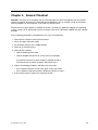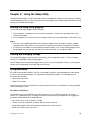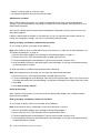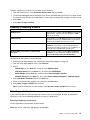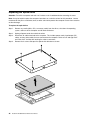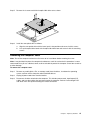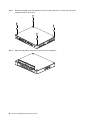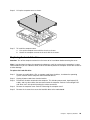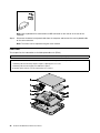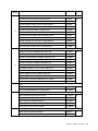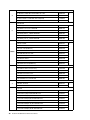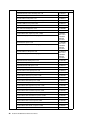
1
IdeaCentre Q190
Hardware Maintenance Manual
ideaideaideaCentreidea
Machine Types: 10115/6281
IdeaCentre Q190
Hardware Maintenance Manual
Machine Types: 10115/6281
Second Edition (December 2012)17th
© Copyright Lenovo 2012.
LIMITED AND RESTRICTED RIGHTS NOTICE: If data or software are delivered pursuant a General Services
Administration “GSA” contract, use, reproduction, or disclosure is subject to restrictions set forth in Contract No.
GS-35F-05925
Contents
Chapter 1. About this manual . . . . . . 1
Important Safety Information . . . . . . . . . .
1
Chapter 2. Safety information . . . . . . 3
General safety . . . . . . . . . . . .
Electrical safety . . . . . . . . . . .
Safety inspection guide . . . . . . . .
Handling electrostatic discharge-sensitive
devices . . . . . . . . . . . . . .
Grounding requirements . . . . . . . .
Safety notices . . . . . . . . . . . .
.
.
.
.
.
.
.
.
.
.
.
.
.
.
.
.
.
.
.
.
.
.
.
.
.
.
.
.
17
17
18
18
21
Locating components, controls and connectors .
Hardware components . . . . . . . . . . .
21
22
. . . .
. . . .
. . . .
5
6
6
Chapter 8. Replacing hardware . . . .
25
9
11
Chapter 5. Using the Setup Utility. . .
13
.
.
.
.
.
.
13
13
13
15
15
16
Chapter 6. Symptom-to-FRU Index . .
17
© Copyright Lenovo 2012
.
.
.
.
Chapter 7. Locations . . . . . . . . .
Chapter 4. General Checkout . . . . .
.
.
.
.
.
.
.
.
.
.
3
3
5
Specifications . . . . . . . . . . . . . . . .
.
.
.
.
.
.
.
.
.
.
. . . .
. . . .
. . . .
Chapter 3. General information . . . . . 9
Starting the Setup Utility program . .
Viewing and changing settings . . .
Using passwords. . . . . . . . .
Enabling or disabling a device . . .
Selecting a startup device . . . . .
Exiting from the Setup Utility program
Hard disk drive boot error
Power Supply Problems .
POST error codes . . .
Undetermined problems .
.
.
.
.
.
.
.
.
.
.
.
.
General information . . . . . . .
Replacing the optical drive . . . .
Removing the computer cover . .
Replacing the hard disk drive . . .
Replacing a memory module . . .
Replacing the WLAN card . . . .
Replacing the heat-sink . . . . .
Replacing the system fan . . . .
Replacing the motherboard. . . .
Replacing the keyboard and mouse
FRU lists . . . . . . . . . . .
.
.
.
.
.
.
.
.
.
.
.
.
.
.
.
.
.
.
.
.
.
.
.
.
.
.
.
.
.
.
.
.
.
.
.
.
.
.
.
.
.
.
.
.
.
.
.
.
.
.
.
.
.
.
.
.
.
.
.
.
.
.
.
.
.
.
25
26
27
29
30
31
32
33
34
35
36
Chapter 9. Additional Service
Information . . . . . . . . . . . . . .
43
iii
iv
IdeaCentre Q190Hardware Maintenance Manual
Chapter 1. About this manual
This manual contains service and reference information for IdeaCentre Q190 computers listed on the cover.
It is intended only for trained servicers who are familiar with Lenovo computer products.
Before servicing a Lenovo product, be sure to read the Safety Information.
The description of the TV card in this manual is only used for the machines which have the TV card. It is
invalid for those machines which do not have TV card.
Important Safety Information
Be sure to read all CAUTION and DANGER sections in this manual before following any of the instructions.
Veuillez lire toutes les consignes de type DANGER et ATTENTION du présent document avant d’exécuter
les instructions.
Lesen Sie unbedingt alle Hinweise vom Typ “ACHTUNG” oder “VORSICHT” in dieser Dokumentation, bevor
Sie irgendwelche Vorgänge durchführen
Leggere le istruzioni introdotte da ATTENZIONE e PERICOLO presenti nel manuale prima di eseguire una
qualsiasi delle istruzioni
Certifique-se de ler todas as instruções de cuidado e perigo neste manual antes de executar qualquer
uma das instruções
Es importante que lea todas las declaraciones de precaución y de peligro de este manual antes de seguir
las instrucciones.
© Copyright Lenovo 2012
1
2
IdeaCentre Q190Hardware Maintenance Manual
Chapter 2. Safety information
This chapter contains the safety information that you need to be familiar with before servicing a computer.
General safety
Follow these rules to ensure general safety:
• Observe good housekeeping in the area of the machines during and after maintenance.
• When lifting any heavy object:
1. Ensure you can stand safely without slipping.
2. Distribute the weight of the object equally between your feet.
3. Use a slow lifting force. Never move suddenly or twist when you attempt to lift.
4. Lift by standing or by pushing up with your leg muscles; this action removes the strain from the
muscles in your back.
Do not attempt to lift any objects that weigh more than 16 kg (35 lb) or objects that you think are
too heavy for you.
• Do not perform any action that causes hazards to the customer, or that makes the equipment unsafe.
• Before you start the machine, ensure that other service representatives and the customer’s personnel are
not in a hazardous position.
• Place removed covers and other parts in a safe place, away from all personnel, while you are servicing
the machine.
• Keep your tool case away from walk areas so that other people will not trip over it.
• Do not wear loose clothing that can be trapped in the moving parts of a machine. Ensure that your sleeves
are fastened or rolled up above your elbows. If your hair is long, fasten it.
• Insert the ends of your necktie or scarf inside clothing or fasten it with a nonconductive clip, approximately
8 centimeters (3 inches) from the end.
• Do not wear jewelry, chains, metal-frame eyeglasses, or metal fasteners for your clothing.
Remember: Metal objects are good electrical conductors.
• Wear safety glasses when you are: hammering, drilling soldering, cutting wire, attaching springs, using
solvents, or working in any other conditions that might be hazardous to your eyes.
• After service, reinstall all safety shields, guards, labels, and ground wires. Replace any safety device
that is worn or defective.
• Reinstall all covers correctly before returning the machine to the customer.
Electrical safety
CAUTION:
Electrical current from power, telephone, and communication cables can be hazardous. To avoid
personal injury or equipment damage, disconnect the attached power cords, telecommunication
systems, networks, and modems before you open the computer covers, unless instructed otherwise
in the installation and configuration procedures.
© Copyright Lenovo 2012
3
Observe the following rules when working on electrical equipment.
Important: Use only approved tools and test equipment. Some hand tools have handles covered with a soft
material that does not insulate you when working with live electrical currents. Many customers have, near
their equipment, rubber floor mats that contain small conductive fibers to decrease electrostatic discharges.
Do not use this type of mat to protect yourself from electrical shock.
• Find the room emergency power-off (EPO) switch, disconnecting switch, or electrical outlet. If an electrical
accident occurs, you can then operate the switch or unplug the power cord quickly.
• Do not work alone under hazardous conditions or near equipment that has hazardous voltages.
• Disconnect all power before:
– Performing a mechanical inspection
– Working near power supplies
– Removing or installing Field Replaceable Units (FRUs)
• Before you start to work on the machine, unplug the power cord. If you cannot unplug it, ask the customer
to power-off the wall box that supplies power to the machine and to lock the wall box in the off position.
• If you need to work on a machine that has exposed electrical circuits, observe the following precautions:
– Ensure that another person, familiar with the power-off controls, is near you.
Remember: Another person must be there to switch off the power, if necessary.
– Use only one hand when working with powered-on electrical equipment; keep the other hand in your
pocket or behind your back.
Remember: There must be a complete circuit to cause electrical shock. By observing the above rule,
you may prevent a current from passing through your body.
– When using a tester, set the controls correctly and use the approved probe leads and accessories for
that tester.
– Stand on suitable rubber mats (obtained locally, if necessary) to insulate you from grounds such as
metal floor strips and machine frames.
Observe the special safety precautions when you work with very high voltages; these instructions are in
the safety sections of maintenance information. Use extreme care when measuring high voltages.
• Regularly inspect and maintain your electrical hand tools for safe operational condition.
• Do not use worn or broken tools and testers.
• Never assume that power has been disconnected from a circuit. First, check that it has been powered-off.
• Always look carefully for possible hazards in your work area. Examples of these hazards are moist floors,
nongrounded power extension cables, power surges, and missing safety grounds.
• Do not touch live electrical circuits with the reflective surface of a plastic dental mirror. The surface is
conductive; such touching can cause personal injury and machine damage.
• Do not service the following parts with the power on when they are removed from their normal operating
places in a machine:
– Power supply units
– Pumps
– Blowers and fans
– Motor generators
and similar units. (This practice ensures correct grounding of the units.)
• If an electrical accident occurs:
– Use caution; do not become a victim yourself.
– Switch off power.
4
IdeaCentre Q190Hardware Maintenance Manual
– Send another person to get medical aid.
Safety inspection guide
The intent of this inspection guide is to assist you in identifying potentially unsafe conditions on these
products. Each machine, as it was designed and built, had required safety items installed to protect users
and service personnel from injury. This guide addresses only those items. However, good judgment should
be used to identify potential safety hazards due to attachment of features or options not covered by this
inspection guide.
If any unsafe conditions are present, you must determine how serious the apparent hazard could be and
whether you can continue without first correcting the problem.
Consider these conditions and the safety hazards they present:
• Electrical hazards, especially primary power (primary voltage on the frame can cause serious or fatal
electrical shock).
• Explosive hazards, such as a damaged CRT face or bulging capacitor
• Mechanical hazards, such as loose or missing hardware
The guide consists of a series of steps presented in a checklist. Begin the checks with the power off, and
the power cord disconnected.
Checklist:
1. Check exterior covers for damage (loose, broken, or sharp edges).
2. Power-off the computer. Disconnect the power cord.
3. Check the power cord for:
a. A third-wire ground connector in good condition. Use a meter to measure third-wire ground
continuity for 0.1 ohm or less between the external ground pin and frame ground.
b. The power cord should be the appropriate type as specified in the parts listings.
c. Insulation must not be frayed or worn.
4. Remove the cover.
5. Check for any obvious alterations. Use good judgment as to the safety of any alterations.
6. Check inside the unit for any obvious unsafe conditions, such as metal filings, contamination, water or
other liquids, or signs of fire or smoke damage.
7. Check for worn, frayed, or pinched cables.
8. Check that the power-supply cover fasteners (screws or rivets) have not been removed or tampered with.
Handling electrostatic discharge-sensitive devices
Any computer part containing transistors or integrated circuits (ICs) should be considered sensitive to
electrostatic discharge (ESD). ESD damage can occur when there is a difference in charge between objects.
Protect against ESD damage by equalizing the charge so that the machine, the part, the work mat, and the
person handling the part are all at the same charge.
Notes:
1. Use product-specific ESD procedures when they exceed the requirements noted here.
2. Make sure that the ESD protective devices you use have been certified (ISO 9000) as fully effective.
When handling ESD-sensitive parts:
• Keep the parts in protective packages until they are inserted into the product.
Chapter 2. Safety information
5
• Avoid contact with other people while handling the part.
• Wear a grounded wrist strap against your skin to eliminate static on your body.
• Prevent the part from touching your clothing. Most clothing is insulative and retains a charge even when
you are wearing a wrist strap.
• Use the black side of a grounded work mat to provide a static-free work surface. The mat is especially
useful when handling ESD-sensitive devices.
• Select a grounding system, such as those listed below, to provide protection that meets the specific
service requirement.
Note: The use of a grounding system is desirable but not required to protect against ESD damage.
– Attach the ESD ground clip to any frame ground, ground braid, or green-wire ground.
– Use an ESD common ground or reference point when working on a double-insulated or
battery-operated system. You can use coax or connector-outside shells on these systems.
– Use the round ground-prong of the ac plug on ac-operated computers.
Grounding requirements
Electrical grounding of the computer is required for operator safety and correct system function. Proper
grounding of the electrical outlet can be verified by a certified electrician.
Safety notices
The caution and danger safety notices in this section are provided in the language of English.
DANGER
Electrical current from power, telephone and communication cables is hazardous.
To avoid a shock hazard:
• Do not connect or disconnect any cables or perform installation, maintenance, or reconfiguration
of this product during an electrical storm.
• Connect all power cords to a properly wired and grounded electrical outlet.
• Connect to properly wired outlets any equipment that will be attached to this product.
• When possible, use one hand only to connect or disconnect signal cables.
• Never turn on any equipment when there is evidence of fire, water, or structural damage.
• Disconnect the attached power cords, telecommunications systems, networks, and modems
before you open the device covers, unless instructed otherwise in the installation and configuration
procedures.
• Connect and disconnect cables as described in the following table when installing, moving, or
opening covers on this product or attached devices.
6
IdeaCentre Q190Hardware Maintenance Manual
To Connect
To Disconnect
1. Turn everything OFF.
1. Turn everything OFF.
2. First, attach all cables to devices.
2. First, remove power cords from outlet.
3. Attach signal cables to connectors.
3. Remove signal cables from connectors.
4. Attach power cords to outlet.
4. Remove all cables from devices.
5. Turn device ON.
CAUTION:
When replacing the lithium battery, use only Part Number 45C1566 or an equivalent type battery
recommended by the manufacturer. If your system has a module containing a lithium battery, replace
it only with the same module type made by the same manufacturer. The battery contains lithium and
can explode if not properly used, handled, or disposed of.
Do not:
• Throw or immerse into water
• Heat to more than 100°C (212°F)
• Repair or disassemble
Dispose of the battery as required by local ordinances or regulations.
CAUTION:
When laser products (such as CD-ROMs, DVD-ROM drives, fiber optic devices, or transmitters) are
installed, note the following:
• Do not remove the covers. Removing the covers of the laser product could result in exposure to
hazardous laser radiation. There are no serviceable parts inside the device.
• Use of controls or adjustments or performance of procedures other than those specified herein
might result in hazardous radiation exposure.
DANGER
Some laser products contain an embedded Class 3A or Class 3B laser diode. Note the following:
Laser radiation when open. Do not stare into the beam, do not view directly with optical
instruments, and avoid direct exposure to the beam.
Chapter 2. Safety information
7
≥18 kg(37 lbs)
≥32 kg(70.5 lbs)
≥55 kg(121.2 lbs)
CAUTION:
Use safe practices when lifting.
CAUTION:
The power control button on the device and the power switch on the power supply do not turn off
the electrical current supplied to the device. The device also might have more than one power
cord. To remove all electrical current from the device, ensure that all power cords are disconnected
from the power source.
2
1
CAUTION:
Do not place any object weighing more than 82 kg (180 lbs.) on top of rack-mounted devices.
8
IdeaCentre Q190Hardware Maintenance Manual
Chapter 3. General information
This chapter provides general information that applies to all machine types supported by this publication.
Specifications
This section lists the physical specifications for your computer.
This section lists the physical specifications for your computer.
Type IdeaCentre Q190
This section lists the physical specifications.
Environment
Air temperature:
Operating: 10° to 35°C
Transit: -20° to 55°C
Humidity:
Operating: 35% to 80%
Transit: 20% to 93% (40°C)
Altitude: 86KPa to 106KPa
Electrical input:
Input voltage: 90V-264V(AC)
Input frequency: 47Hz-63Hz
© Copyright Lenovo 2012
9
10
IdeaCentre Q190Hardware Maintenance Manual
Chapter 4. General Checkout
Attention: The drives in the computer you are servicing might have been rearranged or the drive startup
sequence changed. Be extremely careful during write operations such as copying, saving, or formatting.
Data or programs can be overwritten if you select an incorrect drive.
General error messages appear if a problem or conflict is found by an application program, the operating
system, or both. For an explanation of these messages, refer to the information supplied with that software
package.
Use the following procedure to help determine the cause of the problem:
1. Power-off the computer and all external devices.
2. Check all cables and power cords.
3. Set all display controls to the middle position.
4. Power-on all external devices.
5. Power-on the computer.
• Look for displayed error codes
• Look for readable instructions or a main menu on the display.
If you did not receive the correct response, proceed to step 6.
If you do receive the correct response, proceed to step 7.
6. Look at the following conditions and follow the instructions:
• If the computer displays a POST error, go to “POST error codes”.
• If the computer hangs and no error is displayed, continue at step 7.
7. If you cannot continue, replace the last device tested.
© Copyright Lenovo 2012
11
12
IdeaCentre Q190Hardware Maintenance Manual
Chapter 5. Using the Setup Utility
The Setup Utility program is used to view and change the configuration settings of your computer, regardless
of which operating system you are using. However, the operating-system settings might override any similar
settings in the Setup Utility program.
Starting the Setup Utility program
To start the Setup Utility program, do the following:
1. If your computer is already on when you start this procedure, shut down the operating system and
turn off the computer.
2. Press and hold the F1 key then turn on the computer. When you hear multiple beeps, release the F1 key.
Notes:
1. If you are using a USB keyboard and the Setup Utility program does not display using this method,
repeatedly press and release the F1 key rather than leaving it pressed when turning on the computer.
2. If a Power-On Password or an administrator password has been set, the Setup Utility program menu is
not displayed until you type your password. For more information, see “Using passwords.”
Viewing and changing settings
The Setup Utility program menu lists items that identify system configuration topics. To view or change
settings, see “Starting the Setup Utility program.”
When working with the Setup Utility program menu, you must use the keyboard. The keys used to perform
various tasks are displayed on the right side of each screen.
Using passwords
By using the Setup Utility program, you can set passwords to prevent unauthorized persons from gaining
access to your computer and data. See “Starting the Setup Utility program.” The following types of
passwords are available:
• Administrator Password
• Power-On Password
You do not have to set any passwords to use your computer. However, if you decide to set any passwords,
read the following sections.
Password considerations
A password can be any combination of up to 64 characters (a-z and 0-9) and symbols. For security
reasons, it is a good idea to use a strong password that cannot be easily compromised. We suggest the
passwords should adhere to the following rules:
• Must have at least seven characters in length
• Contain at least one alphabetic character and one numeric character
• Setup Utility program and hard disk drive passwords are not case sensitive
• Not be your name or your user name
© Copyright Lenovo 2012
13
• Not be a common word or a common name
• Be significantly different from your previous password
Administrator password
When a Administrator Password is set, it deters unauthorized persons from changing configuration
settings. If you are responsible for maintaining the settings of several computers, you might want to set a
Administrator Password.
After you set a Administrator Password, a password prompt is displayed each time you try to access the
Setup Utility program.
If both the Administrator and Power-On Password are set, you can type either password. However, to
change any configuration settings, you must use your Administrator password.
Setting, changing, and deleting a Administrator password
To set, change, or delete a password, do the following:
Note: A password can be any combination of up to 64 characters (a-z, and 0-9). For more information, see
“Password considerations” on page 13.
1. Start the Setup Utility program (see “Starting the Setup Utility program” on page 13).
2. From Security menu, select Set Administrator Password and press Enter.
3. The password dialog box will be displayed. Type the new password, and press Enter.
4. when prompted to confirm the password, type the password again. If you type the password correctly,
the password will be installed.
To delete a previously set Administrator password, do the following :
Note: When prompted for a password, you must type your Administrator password.
1. From Security menu, select Set Administrator Password and press Enter.
2. The password dialog box will be displayed. Enter Current Password and press Enter. Press Enter in New
Password and confirm New Password dialog. A setup notice will display that changes have been saved.
3. Select Exit.
4. Select Save changes and Exit.
Power-On Password
When a Power-On Password is set, you cannot start the Setup Utility program until a valid password is
typed from the keyboard.
Setting, changing, and deleting a Power-On Password
To set, change, or delete a Power-On Password, do the following:
Note: A password can be any combination of up to 64 characters(a-z, and 0-9).
1. Start the Setup Utility program (See ”Starting the Setup Utility program”.)
2. From the Security menu, selet Set Power-On Password and press Enter.
3. The password dialog box will be displayed. Type the new password, and press Enter.
4. when prompted to confirm the password, type the password again. If you type the password correctly,
the password will be installed.
14
IdeaCentre Q190Hardware Maintenance Manual
To delete a previously set Power-On Password, do the following :
1. From the Security menu, select Set Power-On Password and press Enter.
2. The password dialog box will be displayed. Enter Current Password and press Enter. Press Enter in New
Password and confirm New Password dialog. A setup notice will display that changes have been saved.
3. Select Exit.
4. Select Save changes and Exit.
Enabling or disabling a device
The Devices options is used to enable or disable user access to the following devices:
USB Functions
Select whether to enable or disable USB (Universal Serial
Bus) functions. If the functions are disabled, no USB
devices can be used.
SATA Controller
When feature is set to Disabled, all devices connected to
the SATA connectors (e.g. hard disk drives or the optical
disk drive) are disabled and can’t be accessed.
Onboard Audio Controller
Select whether to enable or disable the Onboard Audio
Controller, when feature is set to Disabled all devices
connected to the audio connectors (e.g. a headphone or
a microphone) are disabled and can’t be used.
Onboard Ethernet Controller or Onboard PXE
Controller
Select whether to enable or disable Onboard Ethernet
Controller, or select whether to enable or disable load
onboard PXE (Preboot Execution Environment).
To enable or disable a device, do the following:
1. Start the Setup Utility program (see “Starting the Setup Utility program” on page 13).
2. From the Setup Utility program menu, select Devices.
3. Select:
USB Setup press the Enter key, and then select USB Functions.
ATA Drives Setup press the Enter key , and then select SATA Mode.
Audio Setup press the Enter key, and then select Onboard Audio Controller.
Network Setup press the Enter key, then select Onboard Ethernet Support or LAN Boot Agent.
4. Select Disabled or Enabled and press the Enter key.
5. Return to the Setup Utility program menu and select the Exit option.
6. Select Save changes and Exit from the menu.
Note: If you do not want to save the settings, select Discard changes and Exit from the menu.
Selecting a startup device
If your computer does not start up (boot) from a device such as the CD-ROM, diskette, or hard disk as
expected, use one of the following procedures to select a startup device.
Selecting a temporary startup device
Use this procedure to startup from any boot device.
Note: Not all CDs, hard disks, and diskettes are bootable.
Chapter 5. Using the Setup Utility
15
1. Turn off your computer.
2. Press and hold the F12 key then turn on the computer. When the Startup Device Menu appears, release
the F12 key.
Note: If you are using a USB keyboard and the Startup Device Menu does not display using this method,
repeatedly press and release the F12 key rather than leaving it pressed when turning on the computer.
3. Select the desired startup device from the Startup Device Menu and press Enter to begin.
Note: Selecting a startup device from the Startup Device menu does not permanently change the
startup sequence.
Selecting or changing the startup device sequence
To view or permanently change the configured startup device sequence, do the following:
1. Start the Setup Utility program (see “Starting the Setup Utility program” on page 13).
2. Select Start Up.
3. Select Quick Boot Mode, Numlock, Option Keys Display, to set these devices.
4. Select Disabled or Enabled and press Enter.
5. Press ESC to return to Exit and select Save changes and Exit.
If you have changed these settings and want to return to the default settings, select Load Optimal Defaults
on the Setup Utility menu.
Exiting from the Setup Utility program
When you finish viewing or changing settings, press Esc to return to the Setup Utility program menu (you
might have to press Esc several times). If you want to save the new settings, select Save changes and Exit
before you exit. Otherwise, your changes will not be saved.
16
IdeaCentre Q190Hardware Maintenance Manual
Chapter 6. Symptom-to-FRU Index
The Symptom-to-FRU index lists error symptoms and possible causes. The most likely cause is listed first.
Always begin with Chapter 4, “General Checkout,” on page 11. This index can also be used to help you
decide which FRUs to have available when servicing a computer. If you are unable to correct the problem
using this index, go to “Undetermined problems” on page 18.
Notes:
• If you have both an error message and an incorrect audio response diagnose the error message first.
• If you cannot run the diagnostic tests or you get a diagnostic error code when running a test but did
receive a POST error message diagnose the POST error message first.
• If you did not receive any error message look for a description of your error symptoms in the first part of
this index.
Hard disk drive boot error
A hard disk drive boot error (error codes 1962 and I999030X) can have the following causes.
Error
FRU/Action
The start-up drive is not in the boot sequence in
configuration.
Check the configuration and ensure the start-up drive is
in the boot sequence.
No operating system installed on the boot drive.
Install an operating system on the boot drive.
The boot sector on the start-up drive is corrupted.
The drive must be formatted do the following:
1. Attempt to back-up the data on the failing hard disk
drive.
2. Using the operating systems programs format the
hard disk drive.
The drive is defective.
Replace the hard disk drive.
Power Supply Problems
If you suspect a power problem, use the following procedures.
Check/Verify
FRU/Action
Check the following for proper installation.
Reseat connectors
• Power Cord
• On/Off Switch connector
• On/Off Switch Power Supply connector
• System Board Power Supply connectors
• Microprocessor(s) connection
Check the power cord for continuity.
Power Cord
Check the power-on switch for continuity.
Power-on Switch
© Copyright Lenovo 2012
17
POST error codes
Each time you power-on the system, it performs a series of tests that check the operation of the system
and some options. This series of tests is called the Power-On Self-Test, or POST. POST does the following
operations.
• Checks some basic system-board operations
• Checks the memory operation
• Starts the video operation
• Verifies that the boot drive is working
If the POST detects a problem, an error message appears on the screen. A single problem can cause several
error messages to appear. When you correct the cause of the first error message, the other error messages
probably will not appear on the screen the next time you turn on the system.
POST Error Message
Description/Action
CMOS Date/Time Not Set
The CMOS Date and/or Time are invalid. This error can
be resolved by readjusting the system time in AMI BIOS
Setup.
CMOS Battery Low
The CMOS battery is no longer functional. Replace the
battery.
CMOS Checksum Bad
Checksum of CMOS is incorrect. The computer loads the
default configuration settings. This error might indicate
that CMOS has become corrupt due to a weak CMOS
battery.
Primary Master Hard Disk Error
The IDE/ATAPI device configured as Primary
Master/Primary Slave/ Secondary Master/Secondary
Slave could not be found or initialized. Make sure the
hard drive is correctly installed.
Primary Slave Hard Disk Error
Secondary Master Hard Disk Error
Secondary Slave Hard Disk Error
Keyboard error
Cannot initialize the keyboard. Make sure the keyboard
is properly connected to the computer and that no keys
are held pressed during POST. To purposely configure the
computer without a keyboard, set keyboardless operation
in Setup to Enable. The BIOS then ignores the missing
keyboard during POST.
System Halted
The system has been halted. A reset or power cycle is
required to reboot the machine. This message appears
after a fatal error has been detected.
Reboot and Select proper Boot device or Insert Boot
Media in selected Boot device
The BIOS was unable to find a suitable boot device. Make
sure the boot drive is properly connected to the computer.
Make sure you have bootable media.
Undetermined problems
If this computer has a parallel ATA hard disk drive, make sure that the hard disk drive is jumpered as a
master and the optical drive is jumpered as a slave.
1. Power-off the computer.
2. Remove or disconnect the following components (if installed) one at a time.
a. External devices (modem, printer, or mouse)
b. Any adapters
18
IdeaCentre Q190Hardware Maintenance Manual
c. Memory modules
d. Extended video memory
e. External Cache
f. External Cache RAM
g. Hard disk drive
h. Diskette drive
3. Power-on the computer to re-test the system.
4. Repeat steps 1 through 3 until you find the failing device or adapter.
If all devices and adapters have been removed, and the problem continues, replace the system board.
Chapter 6. Symptom-to-FRU Index
19
20
IdeaCentre Q190Hardware Maintenance Manual
Chapter 7. Locations
This section provides illustrations to help locate the various connectors, controls and components of the
computer.
Locating components, controls and connectors
The following illustrations will help you to locate the various components, controls and connectors on your
computer.
Font view
The following illustration shows the location of controls and components on the front of the computer.
1. Eject button
2. Power button
3. Hard disk drive indicator
4. Optical drive (selected models only)
5. Memory card reader
6. USB ports (2)
7. Headphone connector
8. Microphone connector
© Copyright Lenovo 2012
21
Rear view
The following illustration shows the location of connectors on the rear of the computer.
Attention: Be sure not to block any air vents on the computer. Blocked air vents may cause overheating.
1. S/P DIF port
2. VGA connector
3. USB ports (5)
4. HDMI-out port
5. Ethernet connector
6. Power connector
Hardware components
The following illustration shows the components that make up your computer.
22
IdeaCentre Q190Hardware Maintenance Manual
1
2
9
3
8
4
7
5
6
1. Computer cover
6. Chassis
2. System fan
7. RTC battery
3. Heat-sink
8. Memory module
4. Wi-Fi card
9. Hard disk drive
5. Motherboard
Chapter 7. Locations
23
Identifying parts on the motherboard
The motherboard (sometimes called the planar or system board) is the main circuit board in your computer.
It provides basic computing functions and supports a variety of devices that are factory-installed or that you
can install later.
1
17
2
16
3
4
15
5
14
6
13
7
12
8
9
10
11
1. Hard disk drive SATA connector
10. RTC battery
2. Microphone connector
11. Mini PCIE connector
3. Line out connector
12. SPDIF port
4. RTC battery connector
13. VGA connector
5. USB ports (2)
14. USB ports (2)
6. Card reader
15. HDMI-out port
7. Memory slot
16. Ethernet connector
8. Power button
17. Power connector
9. System fan power connector
24
IdeaCentre Q190Hardware Maintenance Manual
Chapter 8. Replacing hardware
Attention: Do not remove the computer cover or attempt any repair before reading the “Important safety information”
in the Safety and Warranty Guide that was included with your computer or in the Hardware Maintenance Manual
(HMM) for the computer. To obtain copies of the Safety and Warranty Guide or HMM, go to the Support Web site
at: http://consumersupport.lenovo.com.
Note: Use only parts provided by Lenovo.
General information
Pre-disassembly instructions
Before proceeding with the disassembly procedure, make sure that you do the following:
1. Turn off the power to the system and all peripherals.
2. Unplug all power and signal cables from the computer.
3. Place the system on a flat, stable surface.
© Copyright Lenovo 2012
25
Replacing the optical drive
Attention: Turn off the computer and wait 3 to 5 minutes to let it cool down before removing the cover.
Note: It may be helpful to place the computer face-down on a soft flat surface for this procedure. Lenovo
recommends that you use a blanket, towel, or other soft cloth to protect the computer screen from scratches
or other damage.
To replace the optical drive
Step 1.
Remove any media (disks, CDs, or memory cards) from the drives, shut down the operating
system, and turn off the computer and all attached devices.
Step 2.
Unplug all power cords from electrical outlets.
Step 3.
Disconnect all cables attached to the computer. This includes power cords, input/output (I/O)
cables, and any other cables that are connected to the computer. Refer to “Left and right view”
and “Rear view” for help with locating the various connectors.
Step 4.
Remove the 4 screws and open the optical disk drive box as shown.
26
IdeaCentre Q190Hardware Maintenance Manual
Step 5.
Remove the 3 screws and slide the optical disk drive out as shown.
Step 6.
Install the new optical drive as follows:
a.
Align the new optical drive with the bezel, push it into position and secure it with 3 screws.
b.
Line up the optical drive bezel with the optical disk drive box and secure it with the remaining
screws.
Removing the computer cover
Note: Turn off the computer and wait 3 to 5 minutes to let it cool down before removing the cover.
Note: It may be helpful to place the computer face-down on a soft flat surface for this procedure. Lenovo
recommends that you use a blanket, towel, or other soft cloth to protect the computer screen from scratches
or other damage.
To remove the computer cover
Step 1.
Remove any media (disks, CDs, or memory cards) from the drives, shut down the operating
system, and turn off the computer and all attached devices.
Step 2.
Unplug all power cords from electrical outlets.
Step 3.
Disconnect all cables attached to the computer. This includes power cords, input/output (I/O)
cables, and any other cables that are connected to the computer. Refer to “Left and right view”
and “Rear view” for help with locating the various connectors.
Chapter 8. Replacing hardware
27
Step 4.
Remove the rubber caps that protects the screws, then remove the 4 screws that secure the
computer cover to the chassis.
Step 5.
Open the side door and remove the cover from this side gently.
28
IdeaCentre Q190Hardware Maintenance Manual
Step 6.
Lift up the computer cover as shown.
Step 7.
To install the computer cover:
a.
Line up the computer cover with the chassis as shown.
b.
Secure the computer cover to the chassis with the 4 screws.
Replacing the hard disk drive
Attention: Turn off the computer and wait 3 to 5 minutes to let it cool down before removing the cover.
Note: It may be helpful to place the computer face-down on a soft flat surface for this procedure. Lenovo
recommends that you use a blanket, towel, or other soft cloth to protect the computer screen from scratches
or other damage.
To replace the hard disk drive
Step 1.
Remove any media (disks, CDs, or memory cards) from the drives, shut down the operating
system, and turn off the computer and all attached devices.
Step 2.
Unplug all power cords from electrical outlets.
Step 3.
Disconnect all cables attached to the computer. This includes power cords, input/output (I/O)
cables, and any other cables that are connected to the computer. Refer to “Left and right view”
and “Rear view” for help with locating the various connectors.
Step 4.
Remove the computer cover. Refer to “Removing the computer cover”.
Step 5.
Remove the 4 screws that secure the hard disk drive to the motherboard.
Chapter 8. Replacing hardware
29
Step 6.
Lift up the back of the hard disk drive and pull it out as shown.
Step 7.
Remove the 4 screws that secure the hard disk drive to the hard disk drive bay.
Step 8.
Slide out the hard disk drive out of the bay to remove
it.
Step 9.
To install the new hard disk drive as follows:
a.
Slide the new hard disk drive bay into bay and secure it to the bay with the 4 screws.
b.
Slide the new hard disk drive and bay into position and secure it to the chassis with the
4 screws.
Step 10. Reattach the computer cover.
Replacing a memory module
Attention: Turn off the computer and wait 3 to 5 minutes to let it cool down before removing the cover.
30
IdeaCentre Q190Hardware Maintenance Manual
Note: It may be helpful to place the computer face-down on a soft flat surface for this procedure. Lenovo
recommends that you use a blanket, towel, or other soft cloth to protect the computer screen from scratches
or other damage.
To replace a memory module
Step 1.
Remove any media (disks, CDs, or memory cards) from the drives, shut down the operating
system, and turn off the computer and all attached devices.
Step 2.
Unplug all power cords from electrical outlets.
Step 3.
Disconnect all cables attached to the computer. This includes power cords, input/output (I/O)
cables, and any other cables that are connected to the computer. Refer to “Left and right view”
and “Rear view” for help with locating the various connectors.
Step 4.
Remove the computer cover. Refer to “Removing the computer cover”.
Step 5.
Push out the latches on both sides of the memory socket to release the memory module. 1
Gently pull the memory module upward to remove it from its socket. 2
1
2
1
Step 6.
Align the new memory module with the memory socket, then insert it and push down on the top
edge. Make sure the latches lock the memory module in place.
Step 7.
Reattach the computer cover and secure it with the screws.
Replacing the WLAN card
Note: Turn off the computer and wait 3 to 5 minutes to let it cool down before removing the cover.
Note: It may be helpful to place the computer face-down on a soft flat surface for this procedure. Lenovo
recommends that you use a blanket, towel, or other soft cloth to protect the computer screen from scratches
or other damage.
To replace the WLAN card:
Step 1.
Remove any media (disks, CDs, or memory cards) from the drives, shut down the operating
system, and turn off the computer and all attached devices.
Step 2.
Unplug all power cords from electrical outlets.
Step 3.
Disconnect all cables attached to the computer. This includes power cords, input/output (I/O)
cables, and any other cables that are connected to the computer. Refer to “Left and right view”
and “Rear view” for help with locating the various connectors.
Step 4.
Remove the computer cover. Refer to “Removing the computer cover”.
Chapter 8. Replacing hardware
31
Step 5.
Disconnect the 2 antenna cables from the WLAN card. 1
Step 6.
Remove the screw that secures the WLAN card to the motherboard. 2
Step 7.
Pull the WLAN card upward to remove it from the card port.
2
1
Step 8.
Line up the new WLAN card, then insert it into the card port and secure it to the motherboard
with the screw.
Step 9.
Connect the 2 antenna cables to the new WLAN card.
Step 10. Reattach the computer cover.
Replacing the heat-sink
Note: Turn off the computer and wait 3 to 5 minutes to let it cool down before removing the cover.
Note: It may be helpful to place the computer face-down on a soft flat surface for this procedure. Lenovo
recommends that you use a blanket, towel, or other soft cloth to protect the computer screen from scratches
or other damage.
To replace the heat-sink:
Step 1.
Remove any media (disks, CDs, or memory cards) from the drives, shut down the operating
system, and turn off the computer and all attached devices.
Step 2.
Unplug all power cords from electrical outlets.
Step 3.
Disconnect all cables attached to the computer. This includes power cords, input/output (I/O)
cables, and any other cables that are connected to the computer. Refer to “Left and right view”
and “Rear view” for help with locating the various connectors.
Step 4.
Remove the computer cover. Refer to “Removing the computer cover”.
Step 5.
Remove the system fan. Refer to “Replacing the system fan”.
32
IdeaCentre Q190Hardware Maintenance Manual
Step 6.
Remove the 4 screws that secure the system fan to the motherboard.
Step 7.
Remove the heat-sink by lifting it up.
Step 8.
To install the new heat-sink:
Step 9.
a.
Line up the new heat-sink with the mounting holes on the chassis and place it into position.
b.
Secure the new heat-sink with the 4 screws.
Reattach the system fan and computer cover.
Replacing the system fan
Note: Turn off the computer and wait 3 to 5 minutes to let it cool down before removing the cover.
Note: It may be helpful to place the computer face-down on a soft flat surface for this procedure. Lenovo
recommends that you use a blanket, towel, or other soft cloth to protect the computer screen from scratches
or other damage.
To replace the system fan:
Step 1.
Remove any media (disks, CDs, or memory cards) from the drives, shut down the operating
system, and turn off the computer and all attached devices.
Step 2.
Unplug all power cords from electrical outlets.
Step 3.
Disconnect all cables attached to the computer. This includes power cords, input/output (I/O)
cables, and any other cables that are connected to the computer. Refer to “Left and right view”
and “Rear view” for help with locating the various connectors.
Step 4.
Remove the computer cover. Refer to “Removing the computer cover”.
Chapter 8. Replacing hardware
33
Step 5.
Remove the 3 screws that secure the system fan to the motherboard.
Step 6.
Disconnect the system fan power cables from the motherboard.
Step 7.
Remove the system fan by lifting it up.
Step 8.
To install the new system fan:
Step 9.
a.
Line up the new system fan with the mounting holes on the chassis and place it into position.
b.
Secure the new system fan with the 3 screws.
c.
Connect the new system fan power cable to the connector on the motherboard.
Reattach the computer cover.
Replacing the motherboard
Note: Turn off the computer and wait 3 to 5 minutes to let it cool down before removing the cover.
Note: It may be helpful to place the computer face-down on a soft flat surface for this procedure. Lenovo
recommends that you use a blanket, towel, or other soft cloth to protect the computer screen from scratches
or other damage.
To replace the motherboard:
Step 1.
Remove any media (disks, CDs, or memory cards) from the drives, shut down the operating
system, and turn off the computer and all attached devices.
Step 2.
Unplug all power cords from electrical outlets.
Step 3.
Disconnect all cables attached to the computer. This includes power cords, input/output (I/O)
cables, and any other cables that are connected to the computer. Refer to “Left and right view”
and “Rear view” for help with locating the various connectors.
Step 4.
Remove the computer cover. Refer to “Removing the computer cover”.
Step 5.
Remove the hard disk drive. Refer to “Replacing the hard disk drive”.
34
IdeaCentre Q190Hardware Maintenance Manual
Step 6.
Remove the memory module. Refer to “Replacing a memory module”.
Step 7.
Remove the WLAN card. Refer to “Replacing the WLAN card”.
Step 8.
Remove the power button. Refer to “Removing the power button”.
Step 9.
Remove the system fan. Refer to “Replacing the system fan”.
Step 10. Remove the heat-sink. Refer to “Replacing the heat-sink”.
Step 11. Remove all the cables connected to the motherboard.
Step 12. Remove the four screws that secure the motherboard to the chassis.
Step 13. Slide the motherboard up then lift it out to remove it.
Step 14. Place the new motherboard into the chassis, aligning the screw holes in the motherboard with
the mounting holes in the chassis.
Step 15. Secure the new motherboard to the chassis using the screw.
Step 16. Attach all related components to the new motherboard.
Step 17. Reattach the computer cover.
Replacing the keyboard and mouse
Attention: Turn off the computer and wait 3 to 5 minutes to let it cool down before removing the cover.
Note: It may be helpful to place the computer face-down on a soft flat surface for this procedure. Lenovo
recommends that you use a blanket, towel, or other soft cloth to protect the computer screen from scratches
or other damage.
To replace the keyboard and mouse
Step 1.
Remove any media (disks, CDs, or memory cards) from the drives, shut down the operating
system, and turn off the computer and all attached devices.
Step 2.
Unplug all power cords from electrical outlets.
Step 3.
Disconnect all cables attached to the computer. This includes power cords, input/output (I/O)
cables, and any other cables that are connected to the computer. Refer to “Left and right view”
and “Rear view” for help with locating the various connectors.
Chapter 8. Replacing hardware
35
Note: Your keyboard will be connected to a USB connector on one side or at the rear of the
computer.
Step 4.
Disconnect the defective keyboard cable from the computer and connect the new keyboard cable
to the same connector.
Note: The mouse can be replaced using the same method.
FRU lists
This chapter lists the information on the field replaceable units (FRUs).
Attention: Be sure to read and understand all the safety information before replacing any FRUs.
Notes: FRUs that have a 1 or 2 in the CRU column are Customer Replaceable Units (CRUs).
• 1 identifies parts that are fairly simple to replace, requiring few or no tools.
• 2 identifies parts that are slightly more difficult to replace.
• N identifies parts that are not to be replaced by the customer.
1
2
9
3
4
8
7
5
6
36
IdeaCentre Q190Hardware Maintenance Manual
Item #
Description
Lenovo P/N
CRU
ID
M471B5773DH0-CK0 2GB D3-1600S RAM-HF
1-100226
N
HMT325S6CFR8C-PB 2GB D3-1600S RAM-HF
1-100227
MT8KTF25664HZ-1G6M1 2GB D3L-1600S RAM-HF
1-100228
Elp_R J2108BDBG-GN-F 2GB D3-1600S RAM
1-100425
M471B5273DH0-CK0 4GB D3-1600S RAM-HF
1-100230
HMT351S6CFR8C-PB 4GB D3-1600S RAM-HF
1-100231
MT16KTF51264HZ-1G6M1 4GB D3L-1600S RAM-HF
1-100232
Elp_R J2108BDBG-GN-F 4GB D3-1600S RAM
1-100426
M471B1G73BH0-CK0-CK0 8GB D3-1600S RAM-HF
1-100234
HMT41GS6MFR8C-PB 8GB D3-1600S RAM-HF
1-100235
MT16JTF1G64HZ-1G6D1 8GB D3-1600S RAM-HF
1-100099
RAM
8
HDD
9
Seagate ST320LT012 5400RPM 7MM 320G HDD
16-200212
WD3200LPVT-08G33T1 7mm 5.4K rpm 320G HDD
16-200265
Hitachi HTS545032A7E380 5400RPM 320G HDD 7mm
16-200068
WD WD3200BPVT 5400RPM 320G HDD
16-200022
Seagate ST500LT012 5400RPM 7MM 500G HDD
16-200211
ST500LM012 5.4K 9.5 500G HDD
16-200210
WD5000LPVT-08G33T1 7mm 5.4K rpm 500G HDD
16-200264
Hitachi HTS545050A7E380 5400RPM 500G HDD 7mm
16-200067
WD WD5000BPVT-24HXZ 5400RPM 500G HDD
16-004846
ST1000LM024 5.4K 9.5 1T HDD
16-200208
WD WD10JPVT-24A1YT0 5400PRM 9.5mm 1T HDD
16-200071
HT HTS541010A9E680 5400RPM 1TB HDD
16-200193
N
SSD
Sandisk U100 SDSA5DK 24G mSATA SSD
16-200252
Samsung MZMPA024HMCD 24G mSATA SSD
16-200256
N
ODD
HLDS CA40N Slim SATA Slot BD Combo
25-205779
Panasonic UJ265 Slot BD Combo
25-209300
SONY Optiarc AD-7800H Slot Rambo
25-203881
Panasonic UJ8C5 Slot Rambo
25-209301
HLDS GA31N Slim SATA Slot DVDRW
25-009580
N
Power Supply
Delta ADP-65YB DA 65W ADAPTER
36200337
Liteon PA-1650-52LC NB Power Adapter (EPS2.0)
36001678
1
Chapter 8. Replacing hardware
37
Wi-Fi Card
4
Cbt BCM4313 MOW M PCIE NB HMC wifi card
20002505
LTN RTL8188EE 11n HMC WiFi card
20200218
LTN RTL8188CE 11n SB HMC WiFi card(wowl)
11200352
Q190 WLAN Antenna(White and black)
90202225
N
Motherboard
5
Q190 NON_WIN8 Celeron 887 HM70 MB
90001754
Q190 WIN8 Celeron 887 HM70 MB
90001755
Q190 WIN8_PRO Celeron 887 HM70 MB
90001756
Q190 NON_WIN8 I3_2365M HM76 MB
90001982
Q190 WIN8 I3_2365M HM76 MB
90001983
Q190 WIN8_PRO I3_2365M HM76 MB
90001984
N
Chasiss
1&6&9
Q190 IO COVER
90202214
Q190 Bottom Case
90202215
Q190 TOP Case(W/Button)
90202216
Q190 ODD Bracket
90202217
Q190 HDD Bracket For HDD
90202218
Q190 HDD Bracket For SSD
90202219
Q190 Bottom Stand
90202220
Q190 ODD Bottom Case
90202221
Q190 ODD TOP Case(W/Button)
90202222
N
Other Connector and Cable
Q180 USB to USB connector assy
31052494
Q180 ODD button cable
31052499
Q190 SSD Connector Card
90001979
Q190 USB to SATA Connection board
90001980
Q190 ODD Button Control Board
90001981
N
Thermal Module
3
Q190 AVC Thermal
90202223
Q190 DELTA FAN
90202224
N
Keyboard
38
Sunrex EKB-10YA(US) B-Silk USB KB-LVT8
25209111
Primax KB4721(US) B-Silk USB KB-LVT8
25209112
Chicony KU-1153(US) B-Silk USB KB-LVT8
25209113
Sunrex EKB-10YA(TW) B-Silk USB KB-LVT8
25209114
Sunrex EKB-10YA(TH) B-Silk USB KB-LVT8
25209115
Sunrex EKB-10YA(CZ-SL) B-S USB KB-LVT8
25209116
Sunrex EKB-10YA(IN) B-Silk USB KB-LVT8
25209117
Sunrex EKB-10YA(RU) B-Silk USB KB-LVT8
25209118
IdeaCentre Q190Hardware Maintenance Manual
1
Sunrex EKB-10YA(UK) B-Silk USB KB-LVT8
25209119
Sunrex EKB-10YA(Nordic) B-S USB KB-LVT8
25209120
Sunrex EKB-10YA(LA) B-Silk USB KB-LVT8
25209121
Sunrex EKB-10YA(AR) B-Silk USB KB-LVT8
25209122
Sunrex EKB-10YA(SW) B-Silk USB KB-LVT8
25209123
Sunrex EKB-10YA(GE) B-Silk USB KB-LVT8
25209124
Sunrex EKB-10YA(TR) B-Silk USB KB-LVT8
25209125
Sunrex EKB-10YA(SP) B-Silk USB KB-LVT8
25209126
Sunrex EKB-10YA(SL) B-Silk USB KB-LVT8
25209127
Sunrex EKB-10YA(IT) B-Silk USB KB-LVT8
25209128
Sunrex EKB-10YA(HB) B-Silk USB KB-LVT8
25209129
Sunrex EKB-10YA(FR) B-Silk USB KB-LVT8
25209130
Sunrex EKB-10YA(GK) B-Silk USB KB-LVT8
25209131
Sunrex EKB-10YA(HG) B-Silk USB KB-LVT8
25209132
Sunrex EKB-10YA(BG) B-Silk USB KB-LVT8
25209133
Sunrex EKB-10YA(HR) B-Silk USB KB-LVT8
25209134
Sunrex EKB-10YA(JP) B-Silk USB KB-LVT8
25209135
Sunrex EKB-10YA(EN-FR) B-S USB KB-LVT8
25209136
Sunrex EKB-10YA(PT) B-Silk USB KB-LVT8
25209137
Sunrex EKB-10YA(BE-EN) B-S USB KB-LVT8
25209138
Sunrex EKB-10YA(DU) B-S USB KB-LVT8
25209139
USB Mouse
Liteon LXH-SM-8825 B-Silk Mouse
25200528
Chicony LXH-MSU-1111 B-Silk Mouse
25200529
Sunrex LXH-EMS-10ZA B-Silk Mouse
25200530
1
2.4GHz Wireless KB/MS
MultimediaRemoteN5902(US-Eng-W8)
25-014044
MultimediaRemoteN5902(FR-Gray-W8)
25-014045
MultimediaRemoteN5902(UK-Gray-W8)
25-014046
MultimediaRemoteN5902(GR-Gray-W8)
25-014048
MultimediaRemoteN5902(LA-SP-Gray-W8)
25-014049
MultimediaRemoteN5902(JP-Gray-W8)
25-014050
1
VESA Mount
Q180 Small VESA Mount W/O ODD
31052512
Q180 Big VESA Mount W/ODD
31052511
N
Chapter 8. Replacing hardware
39
Power Cord
longwell black1.0m 3wire ULCSA power cord
31-033857
Volex 1M C5 US power cord
31-033858
Luxshare1.0M C5 US power cord
31-049517
Grandsun black1.0m3wire CCC power cord(R)
31-032953
Luxshare 1.0M C5 CCC power cord
31-045147
longwell black 1.0m SAA power cord
31-035397
Volex 1M C5 Australia power cord
31-049500
Luxshare1.0M C5 Australia power cord
31-049520
Longwell black1.0m Japan C5 power cord(R)
31038887
line cord +
31039655
3pin2pin
converter
Longwell JPN 3_2pin convert AC plug(R)
Volex1MC5JPN power cord
Longwell JPN 3_2pin convert AC plug(R)
Luxshare1.0M C5 JPN power cord
Longwell JPN 3_2pin convert AC plug(R)
40
31-049506
line cord +
31039655
3pin2pin
converter
31-049519
line cord +
31039655
3pin2pin
converter
longwell black1.0m ASTA power cord
31-035396
Volex1MC5BRT power cord
31-049496
longwell black1.0m VDE power cord
31-035332
Volex1MC5 European power cord
31-049497
Luxshare1.0M C5 European power cord
31-049518
longwell black1.0m India power cord
31-035395
Longwell black1.0m Italy C5 power cord®
31-039104
Volex 1M C5 Italy power cord
31-049504
Longwell black1.0m Brazil power cord®
31-035828
Volex 1M C5 Brazil power cord
31-049505
Longwell black1.0m Argentina C5 power cord®
31-039100
Volex 1M C5 LA power cord
31-049507
Longwell black1.0m Denmark C5 power cord®
31-039101
Volex 1M C5 Danmark power cord
31-049503
Longwell black1.0m Switzerland C5 power cord®
31-039103
Volex 1M C5 Switzerland power cord
31-049508
Longwell black1.0m Israel C5 power cord®
31-039107
Volex 1M C5 Israel power cord
31-049502
Longwell black1.0m Taiwan C5 power cord®
31-038885
Volex 1M C5 TW power cord
31-049499
IdeaCentre Q190Hardware Maintenance Manual
1
Longwell black1.0m Korea C5 power cord®
31-039106
Volex 1MC5 Korea power cord
31-049498
Longwell black1.0m SA C5 power cord®
31-039105
Volex 1M C5 South Africa power cord
31-049501
Chapter 8. Replacing hardware
41
42
IdeaCentre Q190Hardware Maintenance Manual
Chapter 9. Additional Service Information
This chapter provides additional information that the service representative might find helpful.
Power management
Power management reduces the power consumption of certain components of the computer such as the
system power supply, processor, hard disk drives, and some monitors.
Automatic configuration and power interface (ACPI) BIOS
Being an ACPI BIOS system, the operating system is allowed to control the power management features
of the computer and the setting for Advanced Power Management (APM) BIOS mode is ignored. Not
all operating systems support ACPI BIOS mode.
Automatic Power-On features
The Automatic Power-On features within the Power Management menu allow you to enable and disable
features that turn on the computer automatically.
• Resume On RTC Alarm: You can specify a date and time at which the computer will be turned on
automatically. This can be either a single event , a daily event or a weekly event.
• On LAN Wake Up: This feature allows LAN adapter card to wake the System.
© Copyright Lenovo 2012
43