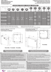
1
Onyx II® Model 9560 Bluetooth® Fingertip Oximeter OEM Specification and Technical Information ® NONIN Medical, Inc. 13700 1st Avenue North Plymouth, Minnesota 55441-5443 USA 763-553-9968 800-356-8874 (USA and Canada) Fax 763-553-7807 E-mail: [email protected] www.nonin.com ® © 2008 NONIN Medical, Inc. 6470-000-01 Table of Contents ® ® NONIN Onyx II Model 9560 Bluetooth Fingertip Oximeter Technology Specifications ................... 1 Input/Output Formatting Options .............................................................................................................. 3 Data Format Solutions .........................................................................................................3 Communications Interface ...................................................................................................3 Selecting the Data Format ............................................................................................................... 4 Setting / Retrieving Time in the 9560............................................................................................... 4 Data Format 13 - SmartPoint™ Algorithm............................................................................5 Data Packet Description.................................................................................................................. 6 Serial Date Format #2:.........................................................................................................8 Packet Description........................................................................................................................... 8 Formatted for Recording Purposes: .............................................................................................. 10 Formatted for Display Purposes: .................................................................................................. 10 Serial Data Format #7:.......................................................................................................12 Packet Description......................................................................................................................... 12 Formatted for Recording Purposes: .............................................................................................. 14 Formatted for Display Purposes: .................................................................................................. 15 Serial Data Format #8........................................................................................................16 Packet Description......................................................................................................................... 16 Indications for Use.................................................................................................................................... 18 Contraindications...................................................................................................................................... 18 Warnings .................................................................................................................................................... 18 Cautions ..................................................................................................................................................... 18 Regulatory Information............................................................................................................................. 20 Declaration of Conformity with FCC and Canadian Ministry of Health Rules for Electromagnetic Compatibility .........................................................................................20 Federal Communications Commission (FCC) Notice .........................................................20 Using the Model 9560 ............................................................................................................................... 21 Guide to Symbols on the Module .......................................................................................21 Installing Batteries .............................................................................................................21 Using Model 9560 and Verifying Operation........................................................................22 Using the Lanyard and Carrying Case ...............................................................................22 Model 9560 Care, Maintenance, and Cleaning ..................................................................23 Cleaning the Inner Surfaces of the Model 9560 ............................................................................ 23 Manufacturer’s Declaration...................................................................................................................... 24 Testing Summary ...................................................................................................................................... 27 SpO2 Accuracy Testing......................................................................................................27 Low Perfusion Testing .......................................................................................................27 i NONIN® Onyx II Model 9560 Bluetooth® Fingertip Oximeter Technology Specifications 1. Oxygen Saturation Range (SpO2) 0 to 100% 2. Pulse Rate Range 18 to 321 beats per minute (BPM) 3. Measurement Wavelengths and Output Power* Red: 660 nanometers @ 0.8 mW maximum average Infrared 910 nanometers @ 1.2 mW maximum average ® (using NONIN PureLight Sensor): 4. SpO2 Accuracy (Arms**) Oxygen Saturation Accuracy Low Perfusion Oxygen Saturation Accuracy: 5. Pulse Rate Accuracy (Arms**) Pulse Rate Accuracy (20-250 BPM): Low Perfusion Pulse Rate Accuracy (40-240 BPM): 70-100% ± 2 digits ± 2 digits ± 3 digits ± 3 digits Internal Power 6. Battery: Operating Life: Storage Life: Two 1.5 volt AAA batteries 600 spot-checks (30 secs/spot-check) in a 6 month period. 12 months 7. Weight 8. Temperature 9. Operating Altitude -40C to +70***C Up to 40,000 feet / 12,192 meters 10. Hyperbaric Pressure Up to 4 atmospheres 11. Humidity 63 grams with batteries installed Operating: Storage/Transportation: Operating: Storage/Transportation: 12. Enclosure Degree of Ingress Protection +5C to +40C 10% to 95% relative humidity, non-condensing 10% to 95% relative humidity, non-condensing Allow to stabilize IP32 * This information is especially useful for clinicians performing photodynamic therapy. ** ±1 Arms represents approximately 68% of measurements. *** When the Model 9560 is transferred from a non-operating temperature/humidity condition, allow one hour of stabilization to operating temperature/humidity specifications prior to use. 1 13. Bluetooth Information Bluetooth Compliance: Operating Frequency: Output Power: Operating Range: Network Topology: Operation: Antenna Type: Modulation Type: Band Width: Bluetooth Profiles Supported: Antenna Type: Antenna Gain: 14. Dimensions 15. Ruggedness Shock: Vibration: 17. ¹ 2 Warranty Line of sight when connected to a class 1 device. Version 2.0 2.4 to 2.4835 GHz <20dBm 100-meter radius indoors¹ Point-to-Point Slave: Model 9560 L-shaped PWB whip-type antenna Frequency Shift Keying Frequency Hopping Spread Spectrum 1 MHz Serial Port Profile Inverted F type antenna +2 dB (typ.), +3 dB (max.) 3.23cm x 6.40cm x 3.78cm (W x H x D) IEC 60068-2-27 Sinusoidal – IEC 60068-2-6 Random – IEC 60068-2-64, IEC 60068-2-36 Bump – IEC 60068-2-29 Two years from the date of purchase. Input/Output Formatting Options Data Format Solutions The 9560 features four data format solutions. They are: Data format 13 – provides easy spot-check measurements with the storage and forwarding of measurements. Data format 8 – provides real-time oximetry measurements every second. Data format 2 – provides real-time oximetry measurements with compressed waveform (8 bit waveform) every th 1/75 of a second. Data format 7 – provides real-time oximetry measurements with full resolution waveform (16 bit waveform) th every 1/75 of a second. For greater detail see the appropriate data format section in this document. Communications Interface Using Bluetooth communications terms, the 9560 oximeter is a slave device. To connect the 9560 oximeter to a master device, the master device must initiate the connection by first pairing with the 9560. The 9560 has a six digit identification number printed on the battery door. To complete the pairing process the six digit number must be provided to the master as the Bluetooth PassKey (Bluetooth PIN). Once the pairing is complete the 9560 will automatically reconnect to the master device when possible. The six digit Bluetooth PassKey on the 9560 must be entered only during the pairing to a new master. Note: To connect to a new device (new master) the 9560 must be out of range from the previous master or unpaired from that master. Specific to Data format 13, after the 9560 turns on and a measurement is available to wirelessly send, the 9560 will send a Bluetooth “Page” message to reestablish the connection with the master with which it is paired. If the master is not available the 9560 will become discoverable for pairing to a new master. For backwards compatibility, when using data formats 2, 7, or 8, the 9560 will not initiate the Bluetooth “Page”. The master must initiate the Bluetooth “Page Scan” to automatically reestablish the connection to the 9560. Once the Bluetooth connection is made the 9560 will automatically send continuous data to the master as defined in the data format sections. For greater detail on establishing a Bluetooth wireless connection refer to Nonin’s Bluetooth Connection Brief. Note: A Bluetooth connection indicator is not available on the 9560 product. Once the Bluetooth connection is established, the 9560 receives and transmits data using the SPP protocol using the following settings: Bits per second Data bits 9600 8 Parity None Stop bits Flow Control 1 None Note: Throughout this document all values are in decimal unless otherwise noted. The decimal number must be converted to 8 bit hex for data transmission. A hex value will be described with this format: 0xZZ, where ZZ is the hex value with a range of 0 to FF. 3 Selecting the Data Format To select the data format the host must send the 9560 the following 6 byte command string: Byte 1 Byte2 Byte3 Byte4 Byte5 Byte6 Start(STX) Op Code Data Size Data Type Data Format ETX 0x02 0x70 0x02 0x02 0xZZ where ZZ is 0x03 (0D, 08, 07, or 02) Response: During the first five seconds from connection after the 9560 receives a command it will respond with an ACK (0x06) for a supported command or NAK (0x15) for an unsupported command. Once the data format is changed, the 9560 will retain the new data format until changed to a different data format. Because the data format is retained in non-volatile memory, the data format will be retained after a battery change. If the data format is not changed the 9560 will default to data format 13. Setting / Retrieving Time in the 9560 The host can set and retrieve the time from the 9560. The date and time must conform to the ranges defined below. The date and time will be lost when replacing the batteries. Name Dec Range YY (year) 00-99 MM (month) 1-12 DD (day) 1-31* hh (hour) 0-23 mm (minute) 0-59 ss (second) 0-59 Comments Depends on leap-year, and month for accurate range Setting the Time: To set the time in the 9560 the host must send the 9560 a 10 byte command. Byte 1 Byte2 Byte3 Byte4 Byte5 Byte6 Byte7 Byte8 Byte9 Byte10 Start(STX) Op Code Data Size Year Month Day Hour Minute Second ETX 0x02 0x72 0x06 YY MM DD hh mm ss 0x03 Example: Date: 12-31-2050 & Time: 14:30:15 (Hours:Minutes:Seconds) Byte 1 Byte2 Byte3 Byte4 Byte5 Byte6 Byte7 Byte8 Byte9 Byte10 Start(STX) Op Code Data Size Year Month Day Hour Minute Second ETX 0x02 0x72 0x06 0x32 0x0C 0x1F 0x0E 0x1E 0x0F 0x03 Response: None. 4 Retrieving Time from the 9560 To retrieve the time from the 9560, the host must send a 4 byte command string. Byte 1 Byte 2 Byte 3 Byte 4 Start (STX) Op Code Data size End(ETX) 02 hex 72 hex 00 03 hex Response: The 9560 sends the date and time as part of the following 10 byte string. Byte 1 Byte2 Byte3 Byte4 Byte5 Byte6 Byte7 Byte8 Byte9 Byte10 Start(STX) Op Code Data Size Year Month Day Hour Minute Second ETX 02 hex F2 hex 06 hex YY MM DD hh mm ss 03 hex Data Format 13 - SmartPoint™ Algorithm Data format 13 uses a SmartPoint Algorithm to determine a reliable single point measurement. The 9560 will acquire a SmartPoint measurement within 40 seconds from power-on. An indicator on the 9560 display flashes while acquiring the measurement and stops flashing after the SmartPoint value is transmitted or stored into memory when a wireless transmission is not possible. If after 40 seconds a high quality measurement is not possible the SmartPoint Algorithm will send the current measurement and mark the measurement as not completing the algorithm. Low perfusion (weak pulse signal conditions) or artifact pulse conditions may affect the ability to obtain the high quality measurement indication. If the 9560 is unable to establish a wireless connection the SmartPoint measurement will be stored into memory. The 9560 has memory capacity to store a minimum of 20 SmartPoint measurements. When a wireless connection is made the 9560 oximeter will forward the oldest stored measurements prior to sending the new measurement. After stored measurements are sent they are removed from memory. Notes: If the finger is removed before 40 seconds and a high quality measurement is not available no data will be sent or stored in memory. Stored measurements will be lost after battery replacement. 5 Data Packet Description The 9560 includes 6 bytes of header information, a minimum of 14 bytes of spot-check data, and 2 bytes of footer information. To determine the total length for the expandable Spot-check data, the host must capture the data length from bytes 5 and 6 of the header. With the minimum data length of 14, the data length defined in bytes 5 and 6 will be (0x00) (0x0E) (14 bytes decimal). The Spot-check data consists of – time of spot-check, SpO2, Pulse Rate, and status. Header Byte # Data Information Format 1 00 NULL start sync Hex 2 02 STX – start of packet Hex 3 00 Packet type MSB Hex 4 0D Packet type LSB Hex 5 00 * Data Length MSB (variable) Hex 6 0E * Data Length LSB (variable) Hex *expandable 7 20 Hundredths place of Year (default to 20) BCD Spot-check 8 Year of Measurement Year of Measurement (00-99) BCD data 9 Month of Measurement Month of Measurement (01-12) BCD 10 Day of Measurement Day of Measurement (01-31 depending on the month) BCD 11 Hour of Measurement Hour of Measurement (00-23) BCD 12 Minute of Measurement Minute of Measurement (00-59) BCD 13 Second of Measurement Second of Measurement (00-59) BCD 14 00 Fraction of second BCD 15 STATUS MSB See STATUS specification below Hex 16 STATUS LSB See STATUS specification below Hex 17 Pulse Rate MSB See HR format below Hex 18 Pulse Rate LSB See HR format below Hex 19 00 to FF Reserved for future use Hex 20 SpO2 See SpO2 format below Hex 21 Checksum LSB LSB of sum of Spot-check Data Hex 22 03 ETX – end of transmission Hex Footer * This data section is expandable. As new parameters are available the data length will increase. The minimum length of the Spot-check Data is 14 bytes (0x0E). 6 Data Format #13 Data Packet Description (continued) Status (MSB) BIT7 BIT6 R BIT5 R BIT4 R R BIT3 BIT2 R R BIT1 SPA BIT0 NOMS Status (LSB) BIT7 BIT6 R BIT5 R R BIT4 MEM BIT3 BIT2 R R BIT1 R BIT0 LOW BAT The following are all active high: SPA: NOMS: MEM: LOW BAT: R: SmartPoint Algorithm High Quality SmartPoint Measurement. No Measurement No measurement for SpO2 or Pulse Rate. From Memory Stored measurement from memory Low Battery condition Low Batteries. Replace batteries as soon as possible. Reserved Reserved for future use 16-Bit HR Format: HR MSB HR LSB 7 6 5 4 3 2 1 0 R R R R R R R HR8 7 6 5 4 3 2 1 0 HR7 HR6 HR5 HR4 HR3 HR2 HR1 HR0 7 6 5 4 3 2 1 0 R SP6 SP5 SP4 SP3 SP2 SP1 SP0 8-Bit SpO2 Format: SpO2 When SpO2 and HR cannot be computed, the system will send a missing data indicator. For missing data, the HR equals 511 and the SpO2 equals 127. The missing data could be result of these conditions: 1. Device is positioned improperly on finger. 2. Device was removed from the finger prior to a reading. 3. Signal at the finger is not discernable - warm the hand. 7 Serial Date Format #2: This data format provides continuous data transmission of a 5 byte data packet sent 75 times per second. The data packet includes real-time data of: 8-bit waveform value, beat-to-beat SpO2 value, SpO2 and Pulse Rates values formatted for both recording and display purposes, status of the measurement and battery. Packet Description A frame consists of 5 bytes; a packet consists of 25 frames. Three packets (75 frames) are transmitted each second. Byte 1 1 2 3 4 5 6 7 8 9 10 11 12 13 14 15 16 17 18 19 20 21 22 23 24 25 01 01 01 01 01 01 01 01 01 01 01 01 01 01 01 01 01 01 01 01 01 01 01 01 01 Byte 2 STATUS STATUS STATUS STATUS STATUS STATUS STATUS STATUS STATUS STATUS STATUS STATUS STATUS STATUS STATUS STATUS STATUS STATUS STATUS STATUS STATUS STATUS STATUS STATUS STATUS Byte 3 PLETH PLETH PLETH PLETH PLETH PLETH PLETH PLETH PLETH PLETH PLETH PLETH PLETH PLETH PLETH PLETH PLETH PLETH PLETH PLETH PLETH PLETH PLETH PLETH PLETH Notes: Byte number 1 in each frame is set to a value of 1. Reserved bytes are undefined (range of 0 to 255). 8 Byte 4 HR MSB HR LSB SpO2 SREV reserved TMR MSB TMR LSB STAT2 SpO2-D SpO2 Fast SpO2 B-B reserved reserved E-HR MSB E-HR LSB E-SpO2 E-SpO2-D reserved reserved HR-D MSB HR-D LSB E-HR-D MSB E-HR-D LSB reserved reserved Byte 5 CHK CHK CHK CHK CHK CHK CHK CHK CHK CHK CHK CHK CHK CHK CHK CHK CHK CHK CHK CHK CHK CHK CHK CHK CHK Byte 1 – START BYTE: Always set to a 01 value. Byte 2 – STATUS BYTE th This byte provides status information at a rate of 1/75 of second. Range: 128 to 255 Byte 2 - Status BIT7 1 BIT6 BIT5 R ARTF BIT4 OOT BIT3 BIT2 BIT1 SNSF YPRF RPRF GPRF BIT0 SYNC *Note: Bit 7 is always set. The following are all active high: R: Reserved Reserved for future use ARTF: Artifact – short term Indicates artifact condition of each pulse (occurs only during pulse) OOT: Out Of Track An absence of consecutive good pulse signals. Indicates sustained periods of Artifact. SNSA: Sensor Alarm Device is providing unusable data for analysis ( set when the finger is removed) RPRF: *Red Perfusion Amplitude representation of low/poor signal quality (occurs only during pulse). YPRF: *Yellow Perfusion Amplitude representation of low/marginal signal quality (occurs only during pulse). GPRF: *Green Perfusion Amplitude representation of high signal quality (occurs only during pulse). SYNC: Frame Sync 1 on Frame 1 (0 on frames 2 through 25). * The oximeter reports each pulse by setting/clearing the RPRF and GPRF bits for a period of 12 frames (160mS). The table below describes the condition and state of the pulse perfusion bits. Condition RPRF Bit 2 of GPRF Bit 1 of Status Byte Status Byte Green – high pulse signal 0 1 Yellow – low/marginal pulse signal 1 1 Red – low/no pulse signal 1 0 Byte 3 – PLETH BYTE This byte consists of an 8 bit plethsmographic waveform (pulse waveform). The pulse oximeter infra-red signal is filtered and then compressed into an 8 bit value. The compression provides good detail for low to large pulse signals. For uncompressed waveform refer to Data Format 7. Range: 00 to 255 9 Byte 4 – FLOAT BYTE This byte is used for SpO2, Pulse Rate, and information that can be processed at a rate of 1/3 of second. Range: 00 to 127 SREV: Oximeter Firmware Revision Level TMR: 1/3 Second Timer, LSB=least significant 7 bits, MSB=most significant 7 bits STAT2: Status Byte 2 (occurs 1 of 25) - description given below Byte 4: STAT2 BIT7 0 LOW BAT: SPA: R: BIT6 BIT5 BIT4 BIT3 BIT2 BIT1 R SPA R R R R BIT0 LOW BAT 1= Low Batteries. Replace batteries as soon as possible. 1 = High Quality SmartPoint Measurement Reserved (range- 0 or 1) Formatted for Recording Purposes: These values are formatted for recording purposes every 1/3 of second. When the finger is removed from the device these values will be formatted with the missing data value. These values are retained for legacy purposes and are formatted with the missing data values during periods of sustained artifact. HR: E-HR: SpO2: E-SpO2: SpO2 Fast: SpO2 B-B: 4-beat Pulse Rate Average 8-beat Pulse Rate Extended Average 4-beat SpO2 Average 8-beat SpO2 Extended Average 4-beat Average optimized for fast responding Beat to Beat value – No Average When SpO2 and HR cannot be computed, the system will send a missing data indicator. For missing data, the HR equals 511 and the SpO2 equals 127. Formatted for Display Purposes: These values are formatted for display purposes every 1.5 seconds. They provide the most reliable readings possible during periods of artifact. When the device is removed from the finger the last SpO2 and Pulse Rate reading will be reported for 10 seconds before changing to the missing data value. During this 10 second period the sensor alarm bit (SNSA) is set, indicating that the finger has been removed. This feature is useful for spot-check measurements. HR-D: E-HR-D: SpO2-D: E-SpO2-D: 4-beat Pulse Rate Average 8-beat Pulse Rate Extended Average 4-beat SpO2 Average 8-beat SpO2 Extended Average When SpO2 and HR cannot be computed, the system will send a missing data indicator. For missing data, the HR equals 511 and the SpO2 equals 127. 10 HR Format: HR MSB HR LSB 7 6 5 4 3 2 1 0 0 R R R R R HR8 HR7 7 6 5 4 3 2 1 0 0 HR6 HR5 HR4 HR3 HR2 HR1 HR0 7 6 5 4 3 2 1 0 0 SP6 SP5 SP4 SP3 SP2 SP1 SP0 SpO2 Format: SpO2 R = Reserved (range 0 or 1) Byte 5 – CHK This byte is used for the checksum of bytes 1 through 4. Range: 00 to 255 CHK: Checksum = (Byte 1) + (Byte 2) + (Byte 3) + (Byte 4) modulo 256 11 Serial Data Format #7: This data format provides the same information as Data Format 2, except that the waveform value provides the full resolution of 16-bits instead of 8-bits. Packet Description A frame consists of 5 bytes; a packet consists of 25 frames. Three packets (75 frames) are transmitted each second. 1 2 3 4 5 6 7 8 9 10 11 12 13 14 15 16 17 18 19 20 21 22 23 24 25 Byte 1 Byte 2 Byte 3 STATUS STATUS STATUS STATUS STATUS STATUS STATUS STATUS STATUS STATUS STATUS STATUS STATUS STATUS STATUS STATUS STATUS STATUS STATUS STATUS STATUS STATUS STATUS STATUS STATUS PLETH MSB PLETH MSB PLETH MSB PLETH MSB PLETH MSB PLETH MSB PLETH MSB PLETH MSB PLETH MSB PLETH MSB PLETH MSB PLETH MSB PLETH MSB PLETH MSB PLETH MSB PLETH MSB PLETH MSB PLETH MSB PLETH MSB PLETH MSB PLETH MSB PLETH MSB PLETH MSB PLETH MSB PLETH MSB PLETH LSB PLETH LSB PLETH LSB PLETH LSB PLETH LSB PLETH LSB PLETH LSB PLETH LSB PLETH LSB PLETH LSB PLETH LSB PLETH LSB PLETH LSB PLETH LSB PLETH LSB PLETH LSB PLETH LSB PLETH LSB PLETH LSB PLETH LSB PLETH LSB PLETH LSB PLETH LSB PLETH LSB PLETH LSB Notes: Byte number 1 in each frame is greater than 127. Reserved bytes are undefined (range of 0 to 255). 12 Byte 4 HR MSB HR LSB SpO2 SREV reserved TMR MSB TMR LSB STAT2 SpO2-D SpO2 Fast SpO2 B-B reserved reserved E-HR MSB E-HR LSB E-SpO2 E-SpO2-D reserved reserved HR-D MSB HR-D LSB E-HR-D MSB E-HR-D LSB reserved reserved Byte 5 CHK CHK CHK CHK CHK CHK CHK CHK CHK CHK CHK CHK CHK CHK CHK CHK CHK CHK CHK CHK CHK CHK CHK CHK CHK Byte 1 – STATUS BYTE This byte provides status information at a rate of 1/75 th of a second. Range: 128 to 255 Byte 1 - Status BIT7 1 BIT6 BIT5 R ARTF BIT4 OOT BIT3 BIT2 BIT1 SNSF YPRF RPRF GPRF BIT0 SYNC *Note: Bit 7 is always set. The following are all active high: R: Reserved Reserved for future use. ARTF: Artifact Indicates artifact condition of each pulse (occurs only during pulse). OOT: Out Of Track An absence of consecutive good pulse signals. Indicates sustained period of Artifact. SNSA: Sensor Alarm Device is providing unusable data for analysis (set when the finger is removed). RPRF: *Red Perfusion Amplitude representation of low/no pulse signal (occurs only during pulse). YPRF: *Yellow Perfusion Amplitude representation of low/marginal signal quality (occurs only during pulse). GPRF: *Green Perfusion Amplitude representation of high signal quality (occurs only during pulse). SYNC: Frame Sync = 1 to Frame 1 (=0 on frames 2 through 25). * The oximeter reports each pulse by setting/clearing the RPRF and GPRF bits for a period of 12 frames (160mS). The table below describes the condition and state of the pulse perfusion bits. Condition RPRF Bit 2 of GPRF Bit 1 of Status Byte Status Byte Green – high pulse signal 0 1 Yellow – low/marginal pulse signal 1 1 Red – low/no pulse signal 1 0 Byte 2 & 3 – PLETH BYTE These two bytes consist of a 16 bit plethsmographic waveform (pulse waveform). Range: 0 to 65535 (MSB:LSB ) Byte 2 = MSB Pulse Waveform Byte 3 = LSB Pulse Waveform Pulse waveform value = (Byte 2 decimal value * 256) + Byte 3 decimal value 13 Byte 4 – FLOAT BYTE This byte is used for SpO2, Pulse Rate, and information that can be processed at a rate of 1/3 of second. Range: 00 to 127 SREV: TMR: STAT2: Oximeter Firmware Revision Level 1/3 Second Timer, LSB=least significant 7 bits, MSB=most significant 7 bits Status Byte 2 (occurs 1 of 25) - description given below Byte 4: STAT2 BIT7 BIT6 BIT5 BIT4 BIT3 BIT2 BIT1 BIT0 0 R SPA R R R R LOW BAT LOW BAT: SPA: R: 1 = Low Batteries. Replace batteries as soon as possible. 1 = High quality SmartPoint Measurement = Reserved (range - 0 or 1) Formatted for Recording Purposes: These values are formatted for recording purposes every 1/3 of second. When the finger is removed from the device these values will immediately be formatted with the missing data value. These values are retained for legacy purposes and are formatted with the missing data values during periods of sustained artifact. HR: E-HR: SpO2: E- SpO2: SpO2 Fast: SpO2 B-B: 4-beat Pulse Rate Average 8-beat Pulse Rate Extended Average 4-beat SpO2 Average 8-beat SpO2 Extended Average 4-beat Average optimized for fast responding Beat to Beat value – No Average When SpO2 and HR cannot be computed, the system will send a missing data indicator. For missing data, the HR equals 511 and the SpO2 equals 127. 14 Formatted for Display Purposes: These values are formatted for display purposes every 1.5 seconds. They provide the most reliable reading possible during periods of artifact. When the device is removed from the finger the last SpO2 and Pulse Rate reading will be reported for 10 seconds before changing to the missing data value. During this 10 second period the sensor alarm bit (SNSA) is set, indicating that the finger has been removed. This feature is useful for spot-check measurements. HR-D: E-HR-D: SpO2-D: E- SpO2-D: 4-beat Pulse Rate Average 8-beat Pulse Rate Extended Average 4-beat SpO2 Average 8-beat SpO2 Extended Average When SpO2 and HR cannot be computed, the system will send a missing data indicator. For missing data, the HR equals 511 and the SpO2 equals 127. HR Format: HR MSB HR LSB 7 6 5 4 3 2 1 0 0 R R R R R HR8 HR7 7 6 5 4 3 2 1 0 0 HR6 HR5 HR4 HR3 HR2 HR1 HR0 7 6 5 4 3 2 1 0 0 SP6 SP5 SP4 SP3 SP2 SP1 SP0 SpO2 Format: SpO2 R = Reserved (range- 0 or 1) Byte 5 – CHK This byte is used for the checksum of bytes 1 through 4. Range: 00 to 255 CHK: Checksum = (Byte 1) + (Byte 2) + (Byte 3) + (Byte 4) modulo 256 15 Serial Data Format #8 This data format provides continuous data transmission of a 4 byte data packet sent once per second. The data packet includes real-time data of: SpO2 and Pulse Rate formatted for display, status information of the measurement, and status of the battery. Packet Description Three bytes of data are transmitted 1 once per second. Byte 1 - Status BIT7 BIT6 BIT5 1 R OOT *Note: Bit 7 is always set BIT4 LPRF BIT3 MPRF BIT2 ARTF BIT1 HR8 BIT0 HR7 Byte 2 - Heart Rate (HR-D BIT7 BIT6 BIT5 0 HR6 HR5 *Note: Bit 7 is always clear BIT4 HR4 BIT3 HR3 BIT2 HR2 BIT1 HR1 BIT0 HR0 Byte 3 - SpO2-D BIT7 BIT6 BIT5 0 SP6 SP5 *Note: Bit 7 is always clear BIT4 SP4 BIT3 SP3 BIT2 SP2 BIT1 SP1 BIT0 SP0 Byte 4 – Status2 BIT7 BIT6 BIT5 0 R SPA *Note: Bit 7 is always clear BIT4 R BIT3 SNSF BIT2 R BIT1 R BIT0 LOW BAT The following are all active high: ARTF: Artifact Indicated artifact condition on each pulse OOT: Out Of Track An absence of consecutive good pulse signals. Indicates sustained period of Artifact LPRF: Low Perfusion Amplitude representation of low/no signal quality (holds for entire duration). MPRF: Marginal Perfusion Amplitude representation of low/marginal signal quality (holds for entire duration). SNSA: Sensor Alarm Device is providing unusable data for analysis (set when the finger is removed) SPA: SmartPoint Algorithm High quality SmartPoint measurement LOW BAT: Low Battery condition Low Batteries. Replace batteries as soon as possible. HR8 – HR0: Heart Rate (HR-D) 4-beat Pulse Rate average formatted for display SP6 – SP0: SpO2 (SpO2-D) 4-beat SpO2 average formatted for display R Reserved (range – 0 or 1) Reserved for future use. 16 The SpO2 and Pulse Rate values are formatted for display purposes every 1.5 seconds. They provide the most reliable reading possible during periods of artifact. When the device is removed from the finger the last SpO2 and Pulse Rate reading will be reported for 10 seconds before changing to the missing data value. During this 10 second period the sensor alarm bit (SNSA) is set, indicating that the finger has been removed. This feature is useful for spot-check measurements. HR-D: 4-beat Pulse Rate Average SpO2-D: 4-beat SpO2 Average When SpO2 and HR cannot be computed, the system will send a missing data indicator. For missing data, the HR equals 511 and the SpO2 equals 127. 17 Indications for Use ® The NONIN Model 9560 Finger Pulse Oximeter is a small, lightweight, portable, wireless device indicated for use in measuring and displaying functional oxygen saturation of arterial hemoglobin (%SpO2) and pulse rate of patients who are well or poorly perfused. It is intended for spot-checking of adult and pediatric patients on fingers (other than the thumb) between 0.3 – 1.0 inch (0.8 – 2.5 cm) thick. Caution: Federal law (USA) restricts this device to sale by or on the order of a licensed practitioner. Contraindications Do not use this module in a Magnetic Resonance (MR) environment. Do not use this device in an explosive atmosphere or in the presence of flammable anesthetics or gases This device is not defibrillation proof per IEC 60601-1:1990 clause 17h. Warnings Use the Model 9560 within its designated range (approximately 328 feet/100 meters, spherical radius, line of sight when connected to a class I device, from patient module to the display). Moving outside this range may cause missing, lost, and / or inaccurate data. This device is intended only as an adjunct in patient assessment. It must be used in conjunction with other methods of assessing clinical signs and symptoms. The device must be able to measure the pulse properly to obtain an accurate SpO2 measurement. Verify that nothing is hindering the pulse measurement before relying on the SpO2 measurement. Operation of this device below the minimum amplitude of 0.3% modulation may cause inaccurate results. General operation of the device may be affected by the use of an electrosurgical unit (ESU). The use of batteries other than those specified in these instructions may result in increased electromagnetic emission and/or decreased immunity of this device. This device should not be used adjacent to or stacked with other equipment. If adjacent or stacked use is necessary, the device should be observed carefully to verify normal operation. Cautions This device is designed to determine the percentage of arterial oxygen saturation of functional hemoglobin. Significant levels of dysfunctional hemoglobin may affect measurement accuracy. This device has no audible alarms and is intended only for spot-checking. This device is designed to determine the percentage of arterial oxygen saturation of functional hemoglobin. Factors that may degrade pulse oximeter performance or affect the accuracy of the measurement include the following: 18 Do not apply the pulse oximeter on the same arm as a blood pressure cuff, arterial catheter or infusion line(s) (IVs) excessive light, such as sunlight or direct home lighting excessive motion moisture in the device improperly applied device finger is outside recommended size range poor pulse quality venous pulsations anemia or low hemoglobin concentrations cardiogreen or other intravascular dyes carboxyhemoglobin methemoglobin dysfunctional hemoglobin Cautions artificial nails or fingernail polish The device may not work when circulation is reduced. Warm or rub the finger, or re-position the device. This device’s display will go blank after 30 seconds of no readings or poor readings. Do not sterilize, autoclave or immerse this device in liquid. Do not use caustic or abrasive cleaning agents or any cleaning products containing ammonium chloride. A flexible circuit connects the two halves. Do not twist or pull the flexible circuit or overextend the device’s spring. Do not hang the lanyard from the device’s flexible circuit/strain relief. A functional tester cannot be used to assess the accuracy of a pulse oximeter monitor or sensor. This equipment complies with IEC EN 60601-1-2:2001 for electromagnetic compatibility for medical electrical equipment and/or systems. This standard is designed to provide reasonable protection against harmful interference in a typical medical installation. However, because of the proliferation of radio-frequency transmitting equipment and other sources of electrical noise in healthcare and other environments, it is possible that high levels of such interference due to close proximity or strength of a source might disrupt the performance of this device. Medical electrical equipment needs special precautions regarding EMC, and all equipment must be installed and put into service according to the EMC information specified in this manual. Portable and mobile RF communications equipment can affect medical electrical equipment. Batteries may leak or explode is used or disposed of improperly. Remove batteries if the device will be stored for more than 30 days. Do not use different types of batteries at the same time. Do not mix fully charged and partially charged batteries at the same time. These actions may cause the batteries to leak. Follow local, state and national governing ordinances and recycling instructions regarding disposal or recycling of the device and device components, including batteries. In compliance with the European Directive on Waste Electrical and Electronic Equipment (WEEE) 2002/96/EC, do not dispose of this product as unsorted municipal waste. This device contains WEEE materials; please contact your distributor regarding take-back or recycling of the device. If you are unsure how to reach your distributor, please call ® NONIN for your distributor’s contact information. 19 Regulatory Information Declaration of Conformity with FCC and Canadian Ministry of Health Rules for Electromagnetic Compatibility Nonin Medical, Inc., of 13700 1st Avenue North, Plymouth, Minnesota, 55441, declares under its sole responsibility that Model 9560, to which this declaration relates, comply with part 15 of the FCC Rules. Operation is subject to the following two conditions: (1) this device may not cause harmful interference, and (2) this device must accept any interference received, including interference that may cause undesired operation. Ministry of Health (Canada), Safety Code 6: standards include a substantial safety margin designed to ensure the safety of all persons, regardless of age and health. The exposure standard for wireless mobile phones employs a unit of measurement known as the Specific Absorption Rate, or SAR. The SAR limit set by the FCC is 1.6W/kg. Federal Communications Commission (FCC) Notice This equipment has been tested and found to comply with the limits for a class B digital device, pursuant to part 15 of the FCC Rules. These limits are designed to provide reasonable protection against harmful interference in a residential installation. This equipment generates, uses, and can radiate radio frequency energy. If not installed and used in accordance with the instructions, it may cause harmful interference to radio or television reception, which can be determined by turning the equipment off and on. The user is encouraged to try to correct the interference by one or more of the following measures: Reorient or relocate the receiving antenna. Increase the distance between the equipment and the receiver. Connect the equipment to an outlet on a circuit different from the outlet where the receiver is connected. Consult the dealer or an experienced radio/TV technician for assistance. RF Exposure: For body worn operation, to maintain compliance with FCC RF exposure guidelines, use only accessories that contain no metallic components and provide a separation distance of 15mm (0.6 inches) to the body. Use of other accessories may violate FCC RF exposure guidelines and should be avoided. The Model 9560 is designed and manufactured not to exceed the emission limits for exposure to radio frequency (RF) energy set by the United States FCC. These limits are part of comprehensive guidelines and establish permitted levels of RF energy for the general population. The guidelines are based on the safety standards previously set by both U.S. and international standards bodies. This EUT has been shown to be capable of compliance for localized specific absorption rate (SAR) for uncontrolled environment/general population exposure limits specified in ANSI/IEEE Std. C95.1-1992 and has been tested in accordance with the measurement procedures specified in FCC/OET Bulletin 65 Supplement C (2001) and IEEE Std. 1528-200X (Draft 6.5, January 2002). The FCC requires the user to be notified that any changes or modifications to this device that are not expressly approved by Nonin Medical, Inc. may void the user’s authority to operate the equipment. 20 Using the Model 9560 Guide to Symbols on the Module Consult Instructions for Use. Caution! Type BF Applied Part (Patient isolation from electrical shock). UL Mark for Canada and the United States with respect to electric shock, fire, and mechanical hazards only in accordance with UL 60601-1 30EM and CAN/CSA C22.2 No. 601.1. CE Marking indicating conformance to EC directive No. 93/42/EEC concerning medical devices. Serial Number Battery Orientation Non-ionizing electromagnetic radiation. Equipment includes RF transmitters; interference may occur in the vicinity of equipment marked with this symbol. Remote Alarms; Not for Continuous Monitoring. Indicates separate collection for electrical and electronic equipment (WEEE). Bluetooth® Installing Batteries ® Two 1.5 volt AAA-size batteries power the Model 9560 for approximately 600 spot checks. NONIN recommends using alkaline batteries (included with each new Model 9560). When batteries are low, the numeric displays flash once per second. Remove batteries if the device will be stored for more than 30 days. Replace low batteries as soon as possible, using the instructions below. Note: Rechargeable batteries may be used; however, they require more frequent replacement. #1 1. Hold the Model 9560 as shown above, pressing upward and then pulling outward slightly with the thumb to release the device’s battery tray. 2. Remove the battery cover and the depleted batteries, disposing of the batteries properly. 3. Insert two new 1.5 volt AAA-size batteries. Follow the polarity markings (+ and -) as illustrated. Proper positioning of the batteries is essential for operation. #3 21 4. Carefully guide the battery cover back onto the Model 9560, pressing downward and pushing inward slightly to resecure the battery cover. Do not force it into place; it fits only when properly positioned. #4 5. Visually inspect to ensure that the battery cover is properly placed. 6. Insert your finger into the device to verify operation. Using Model 9560 and Verifying Operation The Model 9560 contains numeric LEDs that display oxygen saturation and pulse rate. A tricolor LED display provides a visual indication of the pulse signal quality, while blinking at the corresponding pulse rate. This display changes colors to alert you to changes in pulse quality that may affect the readings: green indicates a good pulse signal, yellow indicates a marginal pulse signal and red indicates an inadequate pulse signal. Activate the Model 9560 by inserting the patient’s finger into the unit. The Model 9560 detects the inserted finger and automatically illuminates the displays. Correct positioning of the light emitter and photodetector on the finger is critical for accurate measurements. All emitted light must pass through the fingertip. Caution: Do not apply the pulse oximeter on the same arm as a blood pressure cuff, arterial catheter or infusion line(s) (IVs). While on the finger, do not press the Model 9560 against any surface and do not squeeze or hold it together. The internal spring provides the correct pressure; additional pressure may cause inaccurate readings. 1. Insert the patient’s finger, nail side up, into the Model 9560 until the fingertip touches the built-in stop guide. 2. Make sure the finger is lying flat (not on its side) and is centered within the device. For best results, keep the Model 9560 at the patient’s heart or chest level. 3. If the device does not turn on, remove the finger and wait a few seconds before reinserting it. When a finger is inserted, the Model 9560 performs a brief startup sequence. Verify that all LEDs illuminate during the ® startup sequence. If any LED is not lit, do not use the Model 9560; contact NONIN Technical Service for repair or replacement. In the factory default mode after the startup sequence, the two flashing red bars will appear on the left hand side of the Model 9560 display. Wait until these bars disappear before removing the finger. A minus sign (-) appears in the left-most digit of the %SpO2 display when the Model 9560 senses that the finger has been removed. The last measured SpO2 and pulse rate values freeze for 10 seconds, and then the displays go blank. The device will automatically shut off (to conserve battery life) approximately 20 seconds after the finger is removed, or after a 2-minute period of inadequate pulse signal Using the Lanyard and Carrying Case A lanyard and carrying case are provided for convenience. The Model 9560 will function with or without the lanyard. If lanyard use is desired, thread the lanyard as shown below. 22 Model 9560 Care, Maintenance, and Cleaning The advanced digital circuitry within the Model 9560 requires no calibration or periodic maintenance other than battery replacement. Field repair of the Model 9560 circuitry is not possible. Do not attempt to open the Model 9560 case or repair the electronics. Opening the case will damage the Model 9560 and void the warranty. Do not open the Model 9560 more the 90°, and do not twist or pull on the device when cleaning. Cleaning the Inner Surfaces of the Model 9560 1. Wipe the surfaces with a soft cloth dampened with isopropyl alcohol or a mild detergent; see CAUTION below. If low-level disinfection is required, a cloth dampened with 10% bleach / 90% water solution may also be used. Do not use undiluted bleach or andy cleaning solution other than those recommended here, as permanent damage could result. 2. Dry with a soft cloth, or allow to air dry. Ensure that all surfaces are completely dry. Caution: Do not sterilize, autoclave or immerse this device in liquid. Do not use caustic or abrasive cleaning agents or any cleaning products containing ammonium chloride. 23 Manufacturer’s Declaration See the following tables for specific information regarding this module’s compliance to IEC 60601-1-2:2001. Table 1: Electromagnetic Emissions Emissions Test Compliance Electromagnetic Environment—Guidance This module is intended for use in the electromagnetic environment specified below. The customer and/or user of this device should ensure that it is used in such an environment. RF Emissions CISPR 11 RF Emissions CISPR 11 Harmonic Emissions IEC 61000-3-2 Voltage Fluctuations/ Flicker Emissions IEC 61000-3-3 This module uses RF energy only for its internal function. Therefore, its RF emissions are very low and are not likely to cause any interference in nearby electronic equipment. Group 1 Class B This module is suitable for use in all establishments, including domestic and those directly connected to the public lowvoltage power supply network that supplies buildings used for domestic purposes. N/A N/A Table 2: Electromagnetic Immunity Immunity Test IEC 60601 Test Level Compliance Level Electromagnetic Environment—Guidance This module is intended for use in the electromagnetic environment specified below. The customer and/or user of this device should ensure that it is used in such an environment. Electrostatic ±6 kV contact ±6 kV contact Floors should be wood, concrete, or ceramic tile. If Discharge (ESD) floors are covered with synthetic material, the relative ±8 kV air ±8 kV air humidity should be at least 30%. IEC 61000-4-2 Electrical Fast Mains power quality should be that of a typical Transient/Burst N/A N/A commercial or hospital environment. IEC 61000-4-4 Surge Mains power quality should be that of a typical N/A N/A commercial or hospital environment. IEC 61000-4-5 Voltage dips, short Mains power quality should be that of a typical interruptions, and commercial or hospital environment. If the user of the voltage variations module requires continued operation during power N/A N/A on power supply mains interruptions, it is recommended that the input lines device be powered from an uninterruptible power supply or battery pack. IEC 61000-4-11 Power Frequency Power frequency magnetic fields should be at levels (50/60 Hz) 3 A/m 3 A/m characteristic of a typical location in a typical Magnetic Field commercial or hospital environment. IEC 61000-4-8 Note: UT is the AC mains voltage before application of the test level. 24 Table 3: Guidance and Manufacturer’s Declaration—Electromagnetic Immunity Immunity Test IEC 60601 Test Level Compliance Level Electromagnetic Environment—Guidance This module is intended for use in the electromagnetic environment specified below. The customer and/or user of this module should ensure that it is used in such an environment. Portable and mobile RF communications equipment should be used no closer to any part of the module, including cables, than the recommended separation distance calculated from the equation applicable to the frequency of the transmitter. Recommended Separation Distance Conducted RF IEC 61000-4-6 3 Vrms 150 kHz to 80 MHz 3V Radiated RF IEC 61000-4-3 3 V/m 80 MHz to 2.5 GHz 3 V/m d = 1.17 P d = 1.17 P 80 MHz to 800MHz d = 2.33 P 800MHz to 2.5 GHz where P is the maximum output power rating of the transmitter in watts (W) according to the transmitter manufacturer and d is the recommended separation distance in meters (m). Field strengths from fixed RF transmitters, as determined a, by an electromagnetic site survey should be less than the b compliance level in each frequency range. Interference may occur in the vicinity of equipment marked with the following symbol: Notes: At 80 MHz and 800MHz, the separation distance for the higher frequency range applies. These guidelines may not apply in all situations. Electromagnetic propagation is affected by absorption and reflection from structures, objects, and people. a) Field strengths from fixed transmitters, such as base stations for radio (cellular/cordless) telephones and land mobile radios, amateur radio, AM and FM radio broadcast and TV broadcast cannot be predicted theoretically with accuracy. To assess the electromagnetic environment due to fixed RF transmitters, an electromagnetic site survey should be considered. If the measured field strength in the location in which the device is used exceeds the applicable RF compliance level above, the device should be observed to verify normal operation. If abnormal performance is observed, additional measures may be necessary, such as reorienting or relocating the module. b) Over the frequency range 150 kHz to 80 MHz, field strengths should be less than [3] V/m. 25 Table 4: Recommended Separation Distances The following table describes the recommended separation distances between portable and mobile RF communications equipment and this module. This module is intended for use in an electromagnetic environment in which radiated RF disturbances are controlled. Customers or users of this module can help prevent electromagnetic interference by maintaining a minimum distance between portable and mobile RF communication equipment (transmitters) and the module as recommended below, according to maximum output power of the communications equipment. Separation Distance According to Frequency of Transmitter Rated Maximum Output Power of Transmitter 150 kHz to 80 MHz 80 MHz to 800 MHz 800 MHz to 2.5 GHz d = 1.17 P d = 1.17 P d = 2.33 P W 0.01 0.12 0.12 0.23 0.1 0.37 0.37 0.74 1 1.2 1.2 2.3 10 3.7 3.7 7.4 100 12 12 23 For transmitters rated at a maximum output power not listed above, the recommended separation distance d in meters (m) can be estimated using the equation applicable to the frequency of the transmitter, where P is the maximum output power rating of the transmitter in watts (W) according to the transmitter manufacturer. Notes: At 80 MHz and 800MHz, the separation distance for the higher frequency range applies. 26 These guidelines may not apply in all situations. Electromagnetic propagation is affected by absorption and reflection from structures, objects, and people. Testing Summary ® SpO2 accuracy, motion and low perfusion testing was conducted by NONIN Medical, Incorporated as described below. SpO2 Accuracy Testing SpO2 accuracy testing is conducted during induced hypoxia studies on healthy, non-smoking, light-to-dark-skinned subjects during motion and no-motion conditions in an independent research laboratory. The measured arterial hemoglobin saturation value (SpO2) of the sensors is compared to arterial hemoglobin oxygen (SaO2) value, determined from blood samples with a laboratory co-oximeter. The accuracy of the sensors in comparison to the co-oximeter samples measured over the SpO2 range of 70 – 100%. Accuracy data is calculated using the root-mean-squared (Arms value) for all subjects, per ISO 9919:2005, Standard Specification for Pulse Oximeters for Accuracy. Low Perfusion Testing This test uses an SpO2 Simulator to provide a simulated pulse rate, with adjustable amplitude settings at various SpO2 levels. The module must maintain accuracy in accordance with ISO 9919:2005 for pulse rate and SpO2 at the lowest obtainable pulse amplitude (0.3% modulation). 27