1
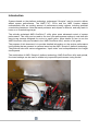
AMD FX Processors Unleashed | a Guide to
Performance Tuning with AMD OverDrive
and the new AMD FX Processors
Disclaimer
The information presented in this document is for informational purposes only and may contain
technical inaccuracies, omissions and typographical errors.
The information contained herein is subject to change and may be rendered inaccurate for many
reasons, including but not limited to product and roadmap changes, component and motherboard
version changes, new model and/or product releases, product differences between differing
manufacturers, software changes, BIOS flashes, firmware upgrades, or the like. AMD assumes no
obligation to update or otherwise correct or revise this information. However, AMD reserves the right
to revise this information and to make changes from time to time to the content hereof without
obligation of AMD to notify any person of such revisions or changes.
AMD MAKES NO REPRESENTATIONS OR WARRANTIES WITH RESPECT TO THE CONTENTS
HEREOF AND ASSUMES NO RESPONSIBILITY FOR ANY INACCURACIES, ERRORS OR
OMISSIONS THAT MAY APPEAR IN THIS INFORMATION.
AMD SPECIFICALLY DISCLAIMS ANY IMPLIED WARRANTIES OF MERCHANTABILITY OR
FITNESS FOR ANY PARTICULAR PURPOSE. IN NO EVENT WILL AMD BE LIABLE TO ANY
PERSON FOR ANY DIRECT, INDIRECT, SPECIAL OR OTHER CONSEQUENTIAL DAMAGES
ARISING FROM THE USE OF ANY INFORMATION CONTAINED HEREIN, EVEN IF AMD IS
EXPRESSLY ADVISED OF THE POSSIBILITY OF SUCH DAMAGES.
WARNING: AMD processors are intended to be operated only within their associated specifications
and factory settings. Operating your AMD processor outside of official AMD specifications or outside
of factory settings, including but not limited to the conducting of overclocking (including use of any
overclocking guide or software, even if such documentation or software has been directly or indirectly
provided by AMD or otherwise affiliated in any way with AMD), may damage your processor and/or
lead to other problems, including but not limited to, damage to your system components (including
your motherboard and components thereon (e.g. memory)); system instabilities (e.g. data loss and
corrupted images); reduction in system performance; shortened processor, system component and/or
system life; and in extreme cases, total unrecoverable system failure. AMD does not provide support
or service for issues or damages related to use of an AMD processor outside of official AMD
specifications or outside of factory settings. You may also not receive support or service from your
board or system manufacturer. Please make sure you have saved all important data before using this
overclocking software. DAMAGES CAUSED BY USE OF YOUR AMD PROCESSOR OUTSIDE OF
OFFICIAL AMD SPECIFICATIONS OR OUTSIDE OF FACTORY SETTINGS ARE NOT COVERED
UNDER ANY AMD PRODUCT WARRANTY AND MAY NOT BE COVERED BY YOUR BOARD OR
SYSTEM MANUFACTURER’S WARRANTY. SEE THE AMD OVERDRIVE UTILITY END USER
LICENSE AGREEMENT OR THE APPLICABLE AMD OVERCLOCKING UTILITY FOR DETAILS.
Use of this documentation is subject to the terms and conditions of the AMD OverDrive™ utility End
User License Agreement. If you have not agreed to the End User License Agreement you do not
have permission to use this guide or the AMD OverDrive™ software.
2
Introduction
Systems based on the platform technology codenamed “Scorpius” may be tuned to deliver
added system performance. The AMD FX™ CPUs and the AMD 9-series chipset
motherboards offer an exciting amount of performance tuning options, including potential
overclocking headroom. Note that each processor and chipset is different, and may result in
lower or no overclocking margin.
The critically acclaimed AMD OverDrive™ utility gives users advanced control of system
performance. This utility can be used to fine tune your performance settings in real time with
easy-to-use screens designed for novice to expert users. More details on how to use the
AMD OverDrive utility are included in the “AMD OverDrive utility” section of this guide.
The purpose of this document is to provide detailed information on the various performance
tuning knobs that are present in systems based on the AMD “Scorpius” platform technology.
The guide will also offer various suggestions, “tips & tricks” and a comprehensive list of target
clock speeds.
The combination of AMD “Scorpius” platform technology, AMD OverDrive utility and optimal,
fine tuned settings can be used to enable truly impressive performance tuning results!
“AMD Scorpius” AM3 platform with aggressive cooling solution has achieved record breaking results.
3
Glossary of Terms
HyperTransport™ Reference Clock (HT ref. clk): The base clock for various clock domains on the AMD
“Scorpius” platform technology. HT ref. clock is 200MHz by default. CPU, CPU NB, HT Link and Memory clocks
are all linked to HT ref. clock. HT ref. clock adjustment is a good tool for fine tuning the various clocks to optimal
values. The HT ref. clock value itself doesn’t have any impact on performance.
CPU: Central Processing Unit – the engine of the AMD “Scorpius” platform technology. CPU core clock
frequency has the biggest impact on overall performance of the system. It’s the primary target of tuning.
CPU NB: CPU NorthBridge (should not be confused with NorthBridge chipset, such as the AMD 990FX chipset)
– part of the CPU that has its own clock domain and voltage plane. CPU NB clock frequency determines the
Memory controller and L3 cache speed. CPU NB has a notable impact on overall system performance.
CPU FID: CPU Core Clock multiplier. In the case of the FX-8150 CPU, the default, base-level CPU multiplier is
x18 (18x200MHz = 3600MHz). CPU Multiplier can be adjusted on the fly with AMD OverDrive™ utility in steps
of 0.5x. CPU Multiplier is unlocked on all of the AMD FX-series CPUs.
CPU NB FID: CPU NB Clock Multiplier. Determines the CPU NB frequency. In the case of the AMD FX-8150
CPU, the default value is x11 (11x200MHz = 2200MHz). CPU NB Multiplier adjustment requires a reboot (it can
not be adjusted on the fly). Can be adjusted in steps of x1. Note that CPU NB clock should be 2x Memory clock
or higher (e.g. DDR3-2400 (1200MHz) would require at least 2400MHz CPU NB clock). CPU NB Multiplier is
unlocked on all of the AMD FX-series CPUs.
HT Link Multiplier: This multiplier determines the clock speed of the HT Link. In the case of the AMD FX-8150
CPU, the default value is x13 (13x200MHz = 2600MHz). In most cases a reboot is required for HT Link
Multiplier value adjustment. The maximum value of HT Link Multiplier is x13. HT Link Multiplier is unlocked on
all of the AMD FX-series CPUs.
CPU VID: CPU Voltage Identification Digital – a register value that programs the motherboard voltage regulator
(VR) to a specific value. In short, the CPU VID determines the CPU Core Voltage level. In the case of the AMD
FX-8150BE CPU, the default CPU base clock VID is usually from 1.250V to 1.350V. The Maximum CPU VID
value is 1.550V. NOTE: VID value may not always equal to the actual voltage level (see “Voltage
OFFSET”). VID value can be adjusted on the fly with AMD OverDrive utility.
CPU NB VID: CPU Voltage Identification Digital – a register value that programs the motherboard voltage
regulator (VR) to a specific value. In short, the CPU NB VID determines the CPU NB Core Voltage level. In the
case of the AMD FX-8150BE CPU the default CPU NB VID is usually 1.100V. The Maximum CPU NB VID
value is 1.550V. NOTE: VID value may not always equal to the actual voltage level (see “Voltage
OFFSET”). VID value can be adjusted on the fly with the AMD OverDrive™ utility.
4
Glossary of Terms – continued
CPU / CPU NB Voltage OFFSET: Most AMD “Scorpius” platform technology motherboards have a BIOS option
that allows Voltage adjustments beyond the CPU VID Voltage range. This voltage offset is added on top of the
VID value. Voltage offset could be negative or positive. Actual voltage level = CPU or CPU NB VID + OFFSET.
Example: VID 1.350V + 0.100V OFFSET = 1.450V actual voltage level.
One of the following options will be available in the BIOS menu (depending on motherboard model):
• “CPU Voltage” and “CPU NB Voltage” item that includes both VID and OFFSET values merged into one
voltage adjustment item (the range can go to over 2.0V)
• Separate items for CPU VID and CPU Voltage – here the “CPU Voltage” value starts from the VID
value and then adds Offset on top of the VID
• CPU and CPU NB “OFFSET” items that control the amount of Voltage offset
In all cases the voltage level can be tuned on the fly with AMD OverDrive utility (VID sliders). Please monitor the
actual voltage level via the Hardware Monitoring.
CPU / CPU NB Voltage OVERRIDE: Some AMD “Scorpius” platform technology motherboards (such as the
ASUS Crosshair 5) have a BIOS option that allows the motherboard to override the CPU VID value requested
by the CPU by directly programming the voltage regulator. In this case the CPU Core Voltage and/or CPU NB
Voltage will remain at a fixed voltage level. The motherboard BIOS may call this option as “manual voltage
mode”. VID Override (or VID Bypass) may allow voltage levels that exceed the range of CPU VID values. In the
case of AMD FX-8150 the VID range enables voltages of up to 1.550V – VID OVERRIDE may allow over 2.0V.
Note: If VID OVERRIDE / Bypass has been activated the CPU VID value adjustments via AMD OverDrive (or
other software) will no longer have any impact on the actual voltage level. The only way to adjust the voltage is
by directly programming the voltage regulator. The motherboard vendor may provide a software for this
purpose.
AMD Turbo Core Technology: AMD Turbo Core Technology and Application Power Management (APM) allow
the CPU cores to run above the CPU Base clock value as long as the CPU remains within the thermal and
power limits. As an example the AMD FX-8150 CPU has a base clock of 3600MHz but it can run at 3900MHz
when up to 8 cores are active and at 4200MHz when up to 4 cores are active assuming it stays within the power
and thermal limits. Under very heavy workloads the CPU will return to the base clock – 3600MHz in the case of
AMD FX-8150 CPU.
Since APM sets a predefined TDP limit it is usually recommended to disable both AMD Turbo Core Technology
and APM features when increasing the CPU frequency and voltage above the default levels. The AMD Turbo
Core Technology and APM can be disabled via AMD OverDrive utility or from the motherboard BIOS menu.
5
AMD OverDrive™ utility
The AMD OverDrive™ utility is a comprehensive utility for performance tuning, system
monitoring and testing. PLEASE NOTE THAT THE AMD PRODUCT WARRANTY DOES
NOT COVER DAMAGES CAUSED BY RUNNING COMPONENTS OUTSIDE OF
SPECIFICATION.
Download from AMD Game! Website - http://sites.amd.com/us/game/downloads/amd-overdrive/Pages/overview.aspx
Advanced Mode
The AMD OverDrive utility is a powerful tool with numerous features and options. However,
in this section we have limited our discussion to only cover the Advanced User mode. The
Advanced User mode of the AMD OverDrive utility allows full control over all the performance
settings. This includes various clock frequency adjustments, clock multiplier settings, voltage
tuning and memory timings.
4
1
5
2
3
Figure 1: Screenshot from AMD OverDrive utility.
* AMD is not responsible for damages caused by overclocking (even when overclocking is enabled with AMD OverDrive™ Software). See
disclaimer on page two (2) for more information.
6
Figure 1, presented above shows all the available clock/voltage tuning options available in
the AMD OverDrive™ utility. The processor, northbridge, PCIe and memory can all be
adjusted to obtain an optimally tuned system.
Detailed description of Figure 1 (AMD OverDrive utility screenshot):
Current clock speeds (1)
PCIe® Speed (5)
This section offers real-time monitoring for all the
crucial clock speeds
This item controls the PCIe® clock frequency of the
PCIe® graphics slots. By default this value is 100MHz.
Increasing this value can provide slightly improved 3D
performance.
Target clock speeds (1)
The values under this section are calculated based
on the clock sliders. It is a convenient way to see the
target clock speeds before actually applying the
settings.
CPU Multiplier (2)
The sliders in this section control the CPU multiplier.
In the case of AMD FX-8150 CPU the best practice is
to adjust all CPU cores to the same value. Target
clock speed (1) should be taken into account when
adjusting CPU Multiplier to ensure that the CPU core
clock speed doesn’t reach unstable value.
The sliders adjust the CPU multiplier of the base
frequency (P0). If the AMD Turbo Core technology
feature is enabled the multiplier range will be limited
to the AMD Turbo Core clock multiplier. Disabling the
Turbo Core will extend the range.
HyperTransport™ (HT) reference clock (3)
Almost all the clocks are based on the HT reference
clock (200MHz by default). Therefore adjusting the
HT reference clock will increase the clock speed of
most key components in the system. This includes
CPU core clock, CPU NB clock (Memory controller),
Memory clock and HT clock frequency. Again,
please refer to the “Target Speed” section before
actually applying the HT reference clock adjustment.
In many cases the HT reference clock margin can be
limited by the System Memory clock. If this is the
case, it is a good idea to adjust the System Memory
settings to a lower value from the System BIOS [e.g.
adjust Memclk mode from DDR3-1833(933MHz) to
DDR3-1600(800MHz) and ensure that safe, manual
memory timings and voltage are applied from the
BIOS.]
HyperTransport™ (HT) Link multiplier (3)
This item can be used to adjust the HT Link multiplier
value.
The range of HT Link multiplier depends on the CPU
capabilities: with HT1 generation CPU the slider can
only go up to X5 (1GHz mode), with HT3 generation
of CPUs it can go up to X13 (2.6GHz mode). If HT3
CPU is booted up in HT1 mode (e.g. X5 or lower HT
Link multiplier) it cannot be adjusted to HT3 mode on
the fly. Switching from HT1 to HT3 mode requires a
BIOS adjustment. In most cases it is best to adjust
the HT Link multiplier from the BIOS.
7
CPU Core voltage adjustment (5)
This item can have two sliders: CPU VID and CPU VDDC.
The amount of sliders depends on the motherboard that is
being used. The CPU VID value is limited to max VID value
(1.55V for instance) supported by the CPU. CPU VDDC (or
CPU Vcore Offset) slider can be used to adjust the CPU
Vcore above the max VID value.
NOTE: If VID OVERRIDE (or “manual mode”) has been
enabled from the BIOS the VID sliders have no impact on
actual voltage level.
NOTE2: The CPU VID slider has no impact on the voltage
that is applied in Turbo Core clock modes. This slider
adjusts the voltage of the base frequency mode (P0). The
range of the slider is limited to the Turbo Core mode
voltage value. Disabling Turbo Core will extend the range
to the maximum supported VID value (1.550V in the case
of the AMD FX-8150 CPU).
Boosting the CPU Vcore voltage can improve the
performance tuning headroom of the CPU Core.
PLEASE NOTE THAT CPU POWER AND THERMAL
REQUIREMENTS INCREASE EXPONENTIALLY WHEN
THE VOLTAGE IS INCREASED. VOLTAGE
ADJUSTMENT IS ALWAYS A RISK AND CAN
DAMAGE THE HARDWARE AND / OR SHORTEN THE
LIFESPAN OF THE CPU OR OTHER COMPONENTS.
System Memory voltage adjustment (5)
This item can also have two sliders (depending on the
motherboard that is being used). “Memory VDDQ”
(memory core voltage) that defaults to 1.5V is the slider
that should be adjusted in most cases. The other slider
(Memory VTT) will adjust automatically according to the
VDDQ slider adjustment. Normally the VTT level should
be 50% of VDDQ level.
Boosting the memory voltage can improve System
memory performance tuning.
PLEASE KEEP IN MIND THAT MEMORY VOLTAGE
ADJUSTMENT CAN DESTROY NOT ONLY THE
MEMORY BUT ALSO THE CPU AND CAN
Chipset voltage controls (5)
There are several voltage rails connected to the AMD 9series chipset. The PCIe® bus, HyperTransport™ link and
Chipset core all have separate voltage rails and controls.
Boosting these voltage levels can result in improved
performance tuning margin for these interfaces. For an
example, boosting the HyperTransport™ link voltage by
0.1V can enable higher HT Link frequencies.
Memory Tuning
1
2
Figure2: AMD OverDrive™ utility Memory Tuning
Memory timing adjustments (1)
Memory Drive strength control (2)
The items circled with red color can directly affect
the overall system performance. Reducing these
values can improve the performance / lower
memory clock tuning margin whereas using higher
values can enable higher memory clock speeds
(but lower clock-to-clock performance).
The lower half of the Memory tuning screen
includes various Drive Strength control items.
PLEASE NOTE THAT SETTING ANY OF THESE
VALUES TO AN INCORRECT / UNSTABLE
VALUE CAN RESULT IN PROGRAM ERRORS
OR SYSTEM CRASH / REBOOT. THE SAFE
DEFAULT SETTINGS WILL BE APPLIED AFTER
REBOOT.
Some of the items are read-only and can only be
adjusted from the System BIOS.
8
Most of these items don’t have an impact on
performance; however, they can improve Memory
clock tuning margin noticeably in some
configurations.
AN INCORRECT SETTING CAN CAUSE THE
SYSTEM TO CRASH / REBOOT.
AMD OverDrive™ utility Stability Test
The AMD OverDrive™ utility features an impressive system stability assessment. The
“Stability Test” tab under “Performance Control” incorporates AMD’s CPU test algorithms to
stress the CPUs worst-case scenario. The test consists of various parts that can be set to run
only on a specific CPU core or on all CPU cores. It is also possible to select only specific
tests to run. The amount of time the test will run can also be adjusted with the slider.
Figure 3: AMD OverDrive™ utility Stability Testing
Switching to other tabs in the AMD OverDrive™ utility does not impact the Stability Test. For
instance, the settings under “Performance Control” can be adjusted while running the
Stability Test.
9
AMD “Scorpius” platform – Performance Tuning Suggestions
CPU Core Clock Performance Tuning
CPU core clock is the most important item to adjust for the advanced users when tuning the performance of the
system. The CPU Clock speed has a big impact on overall system performance. The following steps explain
how to determine the CPU tuning margin.
PLEASE NOTE THAT THE AMD PRODUCT WARRANTY DOES NOT COVER DAMAGES CAUSED BY
RUNNING COMPONENTS OUTSIDE OF SPECIFICATION INCLUDING DAMAGES CAUSED BY
OVERCLOCKING (EVEN WHEN OVERCLOCKING IS ENABLED WITH THE AMD OVERDRIVE UTILITY).
The key BIOS settings to adjust before proceeding with CPU Performance tuning:
•
•
•
•
•
•
Disable AMD Turbo Core Technology (can also be disabled via AMD OverDrive utility)
Disable APM (Application Power Management) (disabling the AMD Turbo Core Technology via
AMD OverDrive utility will also disable APM)
Disable “Cool ‘n’ Quiet” –power saving item from the BIOS menu
Disable “C1E” –item from the BIOS menu
Disable “CPU Fan Control” –item from the BIOS menu (allows max cooling)
Ensure that CPU NB, Memory or HT Link values are running at default stable values
Figure 4: Initial CPU settings from the BIOS menu
Figure 5: Voltage regulator settings for performance tuning (example above for ASUS Crosshair 5)
10
The key settings in the Windows® XP, Windows Vista® or Windows 7® operating system to adjust before
overclocking the CPU:
•
•
•
Close all major applications and background tools and save any open documents
Set OS to “High performance” mode via “Control Panel / Power Options”
Close any third party hardware / clock monitoring and system information programs
CPU tuning with the AMD OverDrive™ utility:
PLEASE NOTE THAT THE AMD PRODUCT WARRANTY DOES NOT COVER DAMAGES CAUSED BY
RUNNING COMPONENTS OUTSIDE OF SPECIFICATION INCLUDING DAMAGES CAUSED BY
OVERCLOCKING (EVEN WHEN OVERCLOCKING IS ENABLED WITH THE AMD OVERDRIVE UTILITY).
1) open AMD OverDrive (“AOD”)
2) enter the “Clock / Voltage” –tab under the “Performance Control” section
3) the two key sliders are “CPU Core Multiplier” and “CPU VID” – monitor the “Target speed” values
before applying them. Make sure that “Select all cores” is checked
Figure 6: AMD OverDrive™ utility CPU Clock multiplier and CPU VID controls
4) increase the values in small steps (example: set CPU Multiplier from x18 to x16 and CPU VID from
1.250V to 1.300V)
5) Verify stability of the new settings with AOD Stability test or with 3rd party multithreaded benchmark
(Cinebench 11.5 or Prime95 for example) or stress tester (OCCT) before increasing the CPU Multiplier
or VID values to the next level. Note that the stress tester must be able to fully stress all CPU cores.
Please refer to “AMD “Scorpius” Platform Technology Performance Tuning Targets” for the expected / optimal
Multiplier and VID values.
HT reference clock slider can be used for finer control over the CPU Core clock. 1MHz HT reference clock
steps are available. This translates to 10-30MHz CPU Core clock steps depending on the CPU Multiplier used.
Note that the motherboard BIOS must enable support for HT reference clock slider – if the BIOS code is
missing then this value cannot be adjusted via AOD. The motherboard vendor may have a software utility
available for this purpose.
11
CPU NorthBridge Performance Tuning
The CPU NorthBridge (CPU NB) clock speed determines the efficiency and bandwidth capacity of the Memory
controller. L3 cache runs at this frequency as well. CPU NB performance tuning gives a measurable boost for
overall system performance. In particular it can reduce the Memory latency and improve L3 cache bandwidth
and latency. In some scenarios the CPU NB should be tuned in order to take the full advantage of overclocked
Memory frequency and bandwidth. In general the CPU NB clock should be at least two times the Memory clock
(example in case of DDR3-1600: 2 x 800MHz = 1600MHz NB clock).
In terms of power delivery and voltage regulation the latest AM2+ and AM3/AM3+ motherboards have a
dedicated power plane for the CPU NB Voltage rail. The voltage level of CPU NB power plane (CPU NB VID)
can be set independently from the CPU Core Voltage rail (CPU VID).
The frequency of CPU NB is determined by the CPU NB Multiplier (CPU NB FID) and by the HT reference clock
(HT ref. clock, 200MHz by default). CPU NB Multiplier can not be changed on the fly (as various memory
parameters and memory training is based on the NB clock value). A reboot is required in order to adjust the
CPU NB Multiplier. Therefore the performance tuning of CPU NB is mostly done thru the BIOS menu. Note that
CPU NB Multipliers are integer values and therefore the adjustment will be in steps of 200MHz or more
(depending on HT ref clock value). The combination of “HT ref clock” and the “CPU NB Multiplier” adjustment in
the BIOS menu will allow finer steps.
HT reference clock adjustments can be done on the fly via the AMD OverDrive™ utility or via the motherboard
vendors utility and this allows finer granularity for CPU NB Performance tuning and may reduce the time
required for tuning (as there is no need to reboot the system between different HT ref. clock values).
PLEASE NOTE THAT THE AMD PRODUCT WARRANTY DOES NOT COVER DAMAGES CAUSED BY
RUNNING COMPONENTS OUTSIDE OF SPECIFICATION INCLUDING DAMAGES CAUSED BY
OVERCLOCKING (EVEN WHEN OVERCLOCKING IS ENABLED WITH THE AMD OVERDRIVE UTILITY).
CPU NB performance tuning with AMD OverDrive™ utility (HT ref. clock):
1) Set CPU NB and HT Link multiplier to known good values (example: 2000MHz or x10)
2) Set CPU Core Multiplier(s) / Voltage to a known stable setting before proceeding with CPU NB
performance tuning (to ensure that CPU core doesn’t cause stability issues / crashes)
3) Set Memory clock and timings to known stable settings (example: DDR3-1333 CL9-9-9) and note that
the Memory interface will also be overclocked when HT ref. clock is adjusted. Memory must be able to
run 10% above the default clock during CPU NB tests. Set Memory to DDR3-1333 (or DDR3-1600
depending on your memory specification) and boost Memory voltage to 1.600V to ensure stability
4) Adjust “HT ref. clock” slider in AOD (2MHz steps for accuracy, 5MHz steps for less accurate but faster
results)
a. NOTE: If you motherboard doesn’t have BIOS support for AOD HT Ref. clock adjustment you
could use the motherboard vendors software utility for this step
12
Figure 7: AMD OverDrive™ utility HT ref. clock slider
5) Run a stability test before increasing the HT ref. clock to another level
6) Adjust CPU NB VID voltage slider in AOD if there were any stability issues (in 0.050V steps – the AMD
FX-8150 CPU may require 1.300…1.375V CPU NB Voltage to reach the full performance tuning
potential on air/watercooling)
a. NOTE: ensure that CPU NB Voltage set to default from the BIOS and that the motherboard is
not overriding the VID value (“manual voltage mode” in some BIOS menus)
7) Once the CPU NB clock has been increased by 200MHz (the next step available via CPU NB Multiplier
change) while maintaining good stability, reboot and enter the BIOS menu in order to increase the NB
Multiplier (see the next section)
8)
PLEASE NOTE THAT THE AMD PRODUCT WARRANTY DOES NOT COVER DAMAGES CAUSED BY
RUNNING COMPONENTS OUTSIDE OF SPECIFICATION INCLUDING DAMAGES CAUSED BY
OVERCLOCKING (EVEN WHEN OVERCLOCKING IS ENABLED WITH THE AMD OVERDRIVE UTILITY).
13
CPU NB performance tuning through the BIOS menu:
1) Set the CPU NB clock speed up to the next available value (example: if 1800MHz / x9 is the default and
NB clock testing via AMD OverDrive utility was OK at 2000MHz then set CPU NB BIOS item to
2000MHz / x10 now)
2) Set CPU NB Voltage to a known stable value (based on the NB clock testing done thru AMD OverDrive
utility)
3) Keep HT Link multiplier at default value or lower it by one step (example: 2400MHz or x12 in the case
of the AMD FX-8150 CPU)
4) Set CPU Core Multiplier(s) / Voltage to a known stable setting before proceeding with CPU NB
performance tuning (to ensure that CPU core doesn’t cause stability issues / crashes)
5) Set Memory clock and timings to known stable settings (example: DDR3-1333 CL9-9-9) note that
Memory interface will also be overclocked when HT ref. clock is adjusted. Memory must be able to run
10% above default clock during the CPU NB tests. Set Memory to DDR3-1333 and boost Memory
voltage to 1.600V to ensure stability
6) Reboot the system with the new CPU NB Multiplier / Voltage value and continue HT ref. clock testing
thru AMD OverDrive™ utility (as instructed in the previous section)
Figure 8: CPU NB settings to adjust from the BIOS menu
The alternative approach is to adjust all the items directly from the BIOS menu and utilize a bootable standalone stability tester such as Memtest86 or Memtest86+ (may be installed on a bootable USB key).
Please refer to “AMD “Scorpius” Platform Technology Performance Tuning Targets” for the expected / optimal
Multiplier and VID values.
PLEASE NOTE THAT THE AMD PRODUCT WARRANTY DOES NOT COVER DAMAGES CAUSED BY
RUNNING COMPONENTS OUTSIDE OF SPECIFICATION INCLUDING DAMAGES CAUSED BY
OVERCLOCKING (EVEN WHEN OVERCLOCKING IS ENABLED WITH THE AMD OVERDRIVE UTILITY).
14
Memory Performance tuning – AM3+ / DDR3
PLEASE NOTE THAT THE AMD PRODUCT WARRANTY DOES NOT COVER DAMAGES CAUSED BY
RUNNING COMPONENTS OUTSIDE OF SPECIFICATION INCLUDING DAMAGES CAUSED BY
OVERCLOCKING (EVEN WHEN OVERCLOCKING IS ENABLED WITH THE AMD OVERDRIVE UTILITY).
Memory clock speed is tied to HT ref. clock with certain ratios. The following Memory clock modes are
available on the AMD “Scorpius” platform technology with AM3+ socket and DDR3 support:
•
•
•
•
•
•
•
DDR3-800 (400MHz) – 2:1 ratio
DDR3-1066 (533MHz) – 8:3 ratio
DDR3-1333 (667MHz) – 10:3 ratio
DDR2-1600 (800MHz) – 4:1 ratio
DDR3-1866 (933MHz) – 14:3 ratio
DDR3-2133 (1066MHz) – 16:3 ratio *
DDR3-2400 (1200MHz) – 6:1 ratio *
(* = not an officially supported memory clock mode
In the case of AM3+ DDR3 platform and AMD FX-series CPUs there are two key strategies for Memory tuning:
1) utilize the maximum memory clock mode that matches your DIMM module specification (or known
performance tuning headroom) - example DDR3-1866 or DDR3-2133 mode with CL9-11-9 timings
2) utilize a lower memory clock mode with faster CL5-5-5…CL7-7-7 timings and HT ref. clock boost (the
amount of HT ref. clock boost will depend on the DIMM OC headroom) – example DDR3-1600 mode
with CL6-6-6 timings
Please refer to the DIMM module specification to determine the optimal Memory voltage value (example 1.65V).
The optimal Tras and Trc timing parameter value is calculated as follows:
Tras = Tcl + Trcd + Trp
Example: Tras should be set to 21 in case of CL7-7-7 -settings
Trc = Tras + Tcl
Example: Trc should be set to 28 in case of CL7 + Tras = 21 -settings
NOTE: Setting Trc to a higher value may improve the margins – example: 42
Enabling 2T –timing mode can improve stability with 4GB or 8GB memory configurations (but will cause a slight
performance hit).
The Memory controller of AMD Phenom and AMD Phenom II CPUs can be set to run in Ganged mode or in
Unganged mode. Ganged mode means that there is a single 128bit wide dual-channel DRAM Controller (DCT)
enabled. Unganged mode enables two 64bit wide DRAM Controllers (DCT0 and DCT1).
The recommended setting in most cases is the Unganged memory mode. Ganged mode may allow slightly
higher Memory performance tuning and performs well in single-threaded benchmarks.
Depending on the motherboard and BIOS, it may be required manually setting the timing parameters for each
DCT (in Unganged mode) when performance tuning the memory or fine tuning the timings. Some BIOS
versions apply the same timings automatically for both DCTs in an Unganged mode.
The DIMM slots furthest away from the CPU socket should be equipped first (usually marked as DIMM slot 1&3
or A2&B2).
15
Advanced Memory tuning examples:
The following BIOS settings may improve the Memory performance tuning margin and enable operation at the
higher memory clock modes (DDR3-1866…2400).
Figure 9: Example settings for DDR3-1866 memory clock mode (2 DIMMs, one DIMM per channel)
16
Figure 10: Example settings for DDR3-2133 memory clock mode (2 DIMMs, one DIMM per channel)
The following memory timing fine tune parameters that may further improve the clock margins and/or stability:
Figure 11: Memory clock fine tuning parameters
NOTE: “Address/CMD Setup Time” & “Address/CMD Fine Delay” –parameters may also be set to “0”
17
HyperTransport™ (HT) reference clock
HT reference clock value has no direct impact on system performance. Therefore the maximum amount of HT
reference clock tuning is not required in order to get the highest performance. HT ref. clock can be used to fine
tune and dial in the other key clock values on the AMD “Scorpius” platform technology. In some cases a
relatively high (over 250MHz) HT reference clock might be required for optimal performance.
In general it’s a good idea to test how high the HT reference clock can be pushed. This is a useful data point to
have when performance tuning the system (even an unlocked CPU).
PLEASE NOTE THAT THE AMD PRODUCT WARRANTY DOES NOT COVER DAMAGES CAUSED BY
RUNNING COMPONENTS OUTSIDE OF SPECIFICATION INCLUDING DAMAGES CAUSED BY
OVERCLOCKING (EVEN WHEN OVERCLOCKING IS ENABLED WITH THE AMD OVERDRIVE UTILITY).
1) Configure CPU, CPU NB, Memory mode, Memory timings and HT Link multiplier to values that allow
good margin for HT reference clock overclocking
o The mentioned clock domains must be able to run at least 20% higher than the specified
multiplier / memclk mode
o This is to ensure that HT ref. clock margin testing is not limited by the other components
2) Load OS and start AMD OverDrive utility or motherboard vendors software utility for HT ref. clock tuning
3) Start the AMD OverDrive utility stability tester
4) Adjust HT reference clock slider in 2MHz steps until the system becomes unstable or hangs
5) Enter the BIOS menu and set HT ref. clock to a value that is a bit lower than the value that previously
failed (example: if 260MHz failed in AMD OVERDRIVE utility, then set BIOS to 255MHz)
o Check that CPU, CPUNB, HT Link and Memory are still at safe values after the HT ref. clock
change. Reduce multiplier values as needed
6) Return to step #2 and repeat until the maximum HT reference clock value is found
Please refer to “AMD “Scorpius” Platform Technology Performance Tuning Targets” for the expected HT ref.
clock tuning margin.
HyperTransport™ (HT) Link frequency
HyperTransport Link frequency will determine the available bandwidth between the CPU and the NorthBridge
Chipset (such as AMD 990FX). In most single CPU socket configurations the default 2.6GHz HT Link value
offers sufficient amount of bandwidth even for multi-GPU configurations.
Similar to CPU and CPU NB clock, the HT Link frequency is tied to HT reference clock (increase in HT ref. clock
will increase the HT Link frequency). Multiplier values from x1 thru x13 are available in case of an unlocked
AMD FX-series AM3+ CPU. It is possible to tune the HT Link frequency by adjusting the HT Link multiplier to a
higher value and / or by increasing the HT reference clock.
In most cases the ideal approach is to adjust the HT Link multiplier to a value that keeps the resulting HT Link
frequency near the default (2600MHz in the case of AMD FX-8150 CPU).
18
AMD “Scorpius” Platform Technology – Performance Tuning
Targets
The following table lists some possible results for an unlocked AMD FX-8150 CPU as well as the optimal
voltage values for most AMD “Scorpius” platform technology systems.
Note that these results are strictly estimates based on overclocking data from a limited sample size. The actual
results will vary depending on the CPU, motherboard, cooling solution and memory modules used in the tests.
The “air cooling” column and the suggested Voltage and Frequency values are based on the assumption that a
high-end heatsink and fan is used.
The “extreme” column lists the suggested Voltage settings and expected target Frequency values for Liquid
Nitrogen (LN2) cooling solution (-196C).
Item
CPU Core clock
CPU NB clock
HT Link clock
DDR3 Memory clock
HT reference clock
Voltage
air cooling
extreme
1.35 - 1.50V
1.35 - 1.45V
1.20 - 1.35V
1.60 - 1.80V
NA
19
1.75 - 2.00V
1.40 - 1.65V
1.20 - 1.35V
1.65 – 1.85V
NA
Frequency
air cooling
extreme
4500 - 5000MHz
2500 - 2700MHz
2600 - 3000MHz
DDR3-1866…2600
250 - 330MHz
6500 - 7500MHz
3700 - 4200MHz
2000 - 3000MHz
DDR3-1866…2800
250 - 400MHz
ATTRIBUTION
© 2011 Advanced Micro Devices, Inc. All rights reserved. AMD, the AMD Arrow logo, ATI,
the ATI logo, , AMD OverDrive and combinations thereof are trademarks of Advanced Micro
Devices, Inc. HyperTransport is a licensed trademark of the HyperTransport Technology
Consortium. PCIe is a registered trademark of PCI-SIG. Windows, Windows 7 and Windows
Vista are registered trademarks of Microsoft Corporation. Other names are for informational
purposes only and may be trademarks of their respective owners.
20