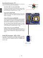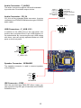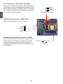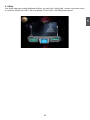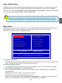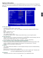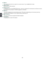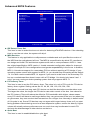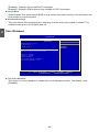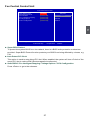
1
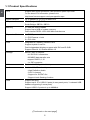
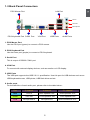
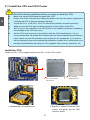
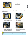
A76GMV Motherboard
User’s Manual
Statement:
This manual is the intellectual property of Foxconn, Inc. Although the information
in this manual may be changed or modified at any time, Foxconn does not obligate
itself to inform the user of these changes.
Trademark:
All trademarks are the property of their respective owners.
Version:
User’s Manual V1.0 for A76GMV motherboard.
CA
UT
IO
N
Symbol description:
!
Caution : refers to important information that can help you to use motherboard
better, and tells you how to avoid problems.
NING
AR
!
W
Warning : indicating a potential risk of hardware damage or physical injury
may exist.
WEEE:
The use of this symbol indicates that this product may not be treated as household
waste. By ensuring this product is disposed of correctly, you will help prevent potential
negative consequences for the environment and human health, which could otherwise be caused by inappropriate waste handling of this product. For more detailed
information about recycling of this product, please contact your local city office, your
household waste disposal service or the shop where you purchased this product.
More information:
If you want more information about our products, please visit Foxconn’s
website: http://www.foxconnchannel.com
© All rights reserved.
All trade names are registered trademarks of respective manufacturers listed.
All images are for reference only, please refer to the physical motherboard for specific features.
Declaration of conformity
HON HAI PRECISION INDUSTRY COMPANY LTD
66 , CHUNG SHAN RD., TU-CHENG INDUSTRIAL DISTRICT,
TAIPEI HSIEN, TAIWAN, R.O.C.
declares that the product
Motherboard A76GMV
is in conformity with
(reference to the specification under which conformity is declared in
accordance with 89/336 EEC-EMC Directive)
■ EN 55022:1998/A2: 2003 Limits and methods of measurements of radio disturbance characteristics of information technology equipment
■ EN 61000-3-2/:2000 Electromagnetic compatibility (EMC)
Part 3: Limits
Section 2: Limits for harmonic current emissions
(equipment input current <= 16A per phase)
■ EN 61000-3-3/A1:2001 Electromagnetic compatibility (EMC)
Part 3: Limits
Section 2: Limits of voltage fluctuations and flicker in low voltage supply systems for equipment with rated current <= 16A
■ EN 55024/A2:2003 Information technology equipment-Immunity characteristics limits and methods of measurement
Signature : Printed Name : James Liang Place / Date : TAIPEI/2010
Declaration of conformity
Trade Name:
FOXCONN
Model Name:
Responsible Party:
Address:
Telephone:
Facsimile:
A76GMV
Equipment Classification:
Type of Product:
Manufacturer:
Address:
FCC Class B Subassembly
Motherboard
HON HAI PRECISION INDUSTRY
COMPANY LTD
66 , CHUNG SHAN RD., TU-CHENG
INDUSTRIAL DISTRICT, TAIPEI HSIEN, TAIWAN, R.O.C.
PCE Industry Inc.
458 E. Lambert Rd.
Fullerton, CA 92835
714-738-8868
714-738-8838
Supplementary Information:
This device complies with Part 15 of the FCC Rules. Operation is subject to the following
two conditions : (1) this device may not cause harmful interference, and (2) this device
must accept any interference received, including interference that may cause undesired
operation.
Tested to comply with FCC standards.
Signature : Date :
2010
Installation Precautions
NING
AR
!
W
■
CA
UT
IO
N
■
!
■
■
■
■
■
■
■
■
Electrostatic discharge (ESD) is the sudden and momentary electric current
that flows between two objects at different electrical potentials. Normally it
comes out as a spark which will quickly damage your electronic equipment.
Please wear an electrostatic discharge (ESD) wrist strap when handling
components such as a motherboard, CPU or memory.
Ensure that the DC power supply is turned off before installing or removing
CPU, memory, expansion cards or other peripherals. It is recommended to
unplug the AC power cord from the power supply outlet. Failure to unplug
the power supply cord may result in serious damage to your system.
Please carefully read the following procedures to install your computer :
It is suggested to select high-quality, certified fans in order to avoid damage
to the motherboard and CPU due to high temperature. Never turn on the
computer if the CPU fan is not properly installed.
We cannot guarantee that your system can operate normally when your
CPU is overclocked. Normal operation depends on the overclocking capacity of your device.
If there is any, when connecting USB, audio, RS232 COM, IrDA or S/PDIF
cables to the internal connectors on the motherboard, make sure their
pinouts are matching with the connectors on the motherboard. Incorrect connections might damage the motherboard.
When handling the motherboard, avoid touching any metal leads or connectors.
If there is a PCI Express x16 graphics card installed in your system, we
recommend using a 24-pin ATX power supply to get the best performance.
Before turning on the power, please make sure the power supply AC input
voltage setting has been configured to the local standard.
To prevent damage to the motherboard, do not allow screws to come in contact
with the motherboard circuit or its components. Also, make sure there are no
leftover screws or metal components placed on the motherboard or within the
computer casing.
If you are uncertain about any installation steps or have a problem related to
the use of the product, please consult a certified computer technician.
Table of Contents
Chapter 1 Product Introduction
Product Specifications...............................................................................2
Layout.......................................................................................................4
Back Panel Connectors.............................................................................5
Chapter 2 Hardware Install
Install the CPU and CPU Cooler...............................................................8
Install the Memory...................................................................................10
Install an Expansion Card.......................................................................12
Install other Internal Connectors.............................................................13
Jumpers...................................................................................................17
Install driver and utility.............................................................................18
Chapter 3 BIOS Setup
Enter BIOS Setup....................................................................................21
Main Menu..............................................................................................21
System Information.................................................................................23
Advanced BIOS Features.......................................................................25
Core Releaser.........................................................................................26
Fox Central Control Unit..........................................................................27
Advanced Chipset Features....................................................................32
Integrated Peripherals.............................................................................36
Power Management Setup......................................................................40
PC Health Status.....................................................................................42
BIOS Security Features..........................................................................43
Load Optimal Defaults.............................................................................43
Save & Exit Setup...................................................................................43
Exit Without Saving.................................................................................43
Chapter 4 RAID Configuration
RAID Introduction....................................................................................45
Install SATA Hard Disks...........................................................................46
RAID Configuration.................................................................................46
Create RAID Driver Disk.........................................................................48
Install Windows OS.................................................................................49
Technical Support :
Support
Website :
http://www.foxconnchannel.com
Support Website :
http://www.foxconnsupport.com
Worldwide Online Contact Support :
http://www.foxconnsupport.com/inquiry.aspx
CPU Support List :
http://www.foxconnsupport.com/cpusupportlist.aspx
Memory, VGA Compatibility List :
http://www.foxconnsupport.com/complist.aspx
Thank you for buying Foxconn A76GMV motherboard. Foxconn
products are engineered to maximize computing power, providing
only what you need for break-through performance.
With advanced overclocking capability and a range of connectivity
features for today multi-media computing requirements, A76GMV
enables you to unleash more power from your computer.
This chapter includes the following information:
■
Product Specifications
■
Layout
■
Back Panel Connectors
1
1-1 Product Specifications
CPU
Support AM3 socket processors, Max processor power up to 95W
For the latest CPU information, please visit:
http://www.foxconnsupport.com/cpusupportlist.aspx
HyperTransport
Up to 4800MT/s (HT3.0) for AM3 CPU
Chipset
North Bridge: AMD 760G
South Bridge: SB700 / SB710
Memory
2 x 240-pin DDR3 DIMMs
Support up to 8GB of system memory
Dual channel DDR3 1333/1066 MHz architecture
Expansion Slots
1 x PCI Express x16 slot
1 x PCI Express x1 slot
2 x PCI slots
VGA
Integrated ATI Radeon HD3000 GPU
Support Hybrid CrossFire
Dual Independent displays support with DVI and D-SUB
Support DirectX 10, Shader Model 4.0
Storage
SB700 / SB710 chipset:
-4 X SATA 2.0 connectors
-300MB/S data transfer rate
-support RAID 0,1,10
-1 x IDE connector
LAN
Realtek 8111E Gigabit LAN chip
Audio
Realtek 662-GR audio chip:
- High Definition Audio
- 2/4/5.1-channel
- Support for S/PDIF Out
- Support Jack-Sensing function
USB
Support hot plug
Support up to 10 x USB 2.0 ports (4 rear panel ports, 3 onboard USB
headers supporting 6 extra ports)
Support USB 2.0 protocol up to 480Mb/s
(Continued on the next page)
1 x 24-pin ATX main power connector
1 x 4-pin ATX 12V power connector
4 x SATA connectors
3 x USB 2.0 connectors (supporting 6 x USB devices)
1 x CPU fan header (4-pin)
1 x System fan header (4-pin)
1 x Front panel connector
1 x CD_IN connector
1 x Front Audio connector
1 x Speaker connector
1 x SPDIF-OUT connector
1 x TPM connector
1 xChassis intrusion alarm header(INTR)
1 x IDE connector
Back Panel
Connectors
1 x PS/2 Keyboard port
1 x PS/2 Mouse port
1 x VGA port
1 x COM1 port
4 x USB 2.0 ports
1 x RJ-45 LAN port
6-channel Audio ports
Hardware Monitor
System voltage detection
CPU/System temperature detection
CPU/System fan speed detection
CPU overheating warning
CPU/System fan speed control
PCI Express x1
Support 500MB/s(1GB/s concurrent) bandwidth
Low power consumption and power management features
PCI Express x16
Support 8GB/s(16GB/s concurrent) bandwidth
Low power consumption and power management features
Green Function
Support ACPI (Advanced Configuration and Power Interface)
Support S0 (normal), S1 (power on suspend), S3 (suspend to RAM),
S4 (suspend to disk), S5 (soft - off)
Support EuP function
Bundled Software
FOX ONE
FOX LiveUpdate
FOX LOGO
FOX DMI
Operating System
Support for Microsoft® Windows® 7/Vista/XP
Form Factor
Micro ATX Form Factor, 9.6inches x 8.4inches (24.4cm x 21.3cm)
1
Internal Connectors
1
1-2 Layout
6
5
3
4
2
1
7
8
9
22
10
11
21
12
13
14
15
16
17
18
19
20
12. Clear CMOS Jumper
13. Speaker Connector
14. Front Panel Connector
15. SATA Connectors
16. IDE Connector
17. 24-pin ATX Power Connector
18. TPM Connector
19. Chassis intrusion alarm header(INTR)
20. SYS_FAN Header
21. DDR3 DIMM Slots
22. CPU Socket
1. 4-pin ATX 12V Power Connector
2. CPU_FAN Header
3. North Bridge: AMD 760G
4. PCI Express x1 Slot
5. PCI Express x16 Slot
6. PCI Slots
7. Front Audio Connector
8.CD_IN Connector
9. SPDIF_OUT Connector
10. Front USB Connectors
11. South Bridge: SB710 / SB710
Note : The above motherboard layout is for reference only, please refer to the physical motherboard for detail.
1-3 Back Panel Connectors
LAN Port
1
PS/2 Mouse Port
7
1
Line In
Line Out
Microphone
2
3
PS/2 Keyboard Port COM1 Port
6
5
4
VGA Port
USB Ports
Audio Ports
1. PS/2 Mouse Port
Use the PS/2 port (green) to connect a PS/2 mouse.
2. PS/2 Keyboard Port
Use the lower port (purple) to connect a PS/2 keyboard.
3. Serial Port
This is output of RS232 COM1 port.
4. VGA Port
To connect with external display devices, such as monitor or LCD display.
5. USB Ports
The USB port supports the USB 2.0/1.1 specification. Use this port for USB devices such as an
USB keyboard/mouse, USB printer, USB flash drive and etc.
6. Audio ports
For the definition of each audio port, please refer to the table below :
Port
2-channel
4-channel
5.1-channel
Blue
Line In
Rear Speaker Out*
Rear Speaker Out*
Green
Line Out
Front Speaker Out
Front Speaker Out
Pink
Microphone In
Microphone In
Center/Subwoofer Out*
1
7. RJ-45 LAN Port
The Ethernet LAN port provides Internet connection at up to 10/100/1000Mb/s data rate.
LAN Type
1000M
Left: Active
Right: Link
Status
Description
Status
Off
No Link
Off
No Link
Off
10 Mb/s Connection
Green
100 Mb/s Connection
Orange
1000 Mb/s Connection
Green
Blinking
Data Activity
Description
Active
LED
Link
LED
This chapter introduces the hardware and software installation process, including the installation of the CPU, memory, power supply,
slots, pin headers and the mounting of jumpers. Caution should be
exercised during the installation of these modules. Please refer to the
motherboard layout prior to any installation and read the contents in
this chapter carefully.
This chapter includes the following information :
■
Install the CPU and CPU Cooler
■
Install the Memory
■
Install an Expansion Card
■
■
■
Install other Internal Connectors
Jumpers
Install driver and utility
Please visit the following website for more supporting information about your motherboard.
CPU Support List:
http://www.foxconnsupport.com/cpusupportlist.aspx
Memory, VGA Compatibility List:
http://www.foxconnsupport.com/complist.aspx
CA
UT
IO
N
2-1 Install the CPU and CPU Cooler
!
2
■
■
■
■
■
■
Read the following guidelines before you begin to install the CPU:
Make sure that the motherboard supports the CPU.
Always turn off the computer and unplug the power cord from the power supply before
installing the CPU to prevent hardware damage.
Locate the Pin-1 of the CPU. The CPU cannot be inserted if oriented incorrectly.
Apply an even and thin layer of thermal grease on the surface of the CPU.
Do not turn on the computer if the CPU cooler is not installed, otherwise overheating
and damage of the CPU may occur.
Set the CPU host frequency in accordance with the CPU specifications. It is not
recommended that the system bus frequency be set beyond hardware specifications
since it does not meet the standard requirements for the peripherals. If you want to
set the frequency beyond the standard specifications, please do so according to your
hardware specifications including the CPU, graphics card, memory, hard drive, etc.
Install the CPU
Locate the Pin-1 CPU triangle mark and the Pin-1 of the CPU socket.
Pin-1 corner of the
CPU socket
Pin-1 triangle
marking of CPU
2. Align Pin-1 of the CPU with the CPU
socket, and gently put the CPU
onto the socket.
1. Release the CPU socket lever.
3. When CPU is properly seated,
push the CPU socket lever back
to its locked position.
2
Install the CPU Cooler
Follow the steps below to correctly install the CPU cooler. (The following procedures use Foxconn
cooler as the example.)
CA
UT
IO
N
!
1. Apply and spread an even thermal
grease on the surface of CPU.
2. Buckle the heatsink firmly at one
side of the stand.
3. Buckle the heatsink at another
side, and press the fasten lever
down to tightly seat the cooler.
4. Attach the CPU cooler connector
to the CPU fan header on the
motherboard .
Use extreme care when removing the CPU cooler because the thermal grease may
adhere to the CPU. Inadequately removing the CPU cooler may damage the CPU.
CA
UT
IO
N
2-2 Install the Memory
!
2
■
■
■
Read the following guidelines before you begin to install the memory :
Make sure that the motherboard supports the memory. It is recommended that memory
of the same capacity, brand, speed, and chips be used.
Always turn off the computer and unplug the power cord from the power outlet before
installing the memory to prevent hardware damage.
Memory modules have a foolproof design. A memory module can be installed in only
one direction. If you are unable to insert the memory, switch the direction.
Dual Channel Memory Configuration
This motherboard provides two DDR3 memory sockets and supports Dual Channel Technology.
When memory is installed, the BIOS will automatically check the memory in your system.
Two DDR3 memory sockets are divided into two channels :
Channel 0 : DIMM1
Channel 1 : DIMM2
The combinations of DIMM modules are :
DIMM1
DIMM2
Single Channel
DS/SS
-
Single Channel
-
DS/SS
Dual Channel
DS/SS
DS/SS
CA
UT
IO
N
(DS : Dual Side, SS : Single Side, - : No Memory)
!
It is recommended that memory of the same capacity, brand, speed, and chips be used and please select dual channel first to achieve optimum performance.
10
CA
UT
IO
N
Installing a Memory
!
Before installing a memory module, make sure to turn off the computer and unplug the
power cord from the power outlet to prevent damage to the memory module. Be sure
to install DDR3 DIMMs on this motherboard.
96-Pin
144-Pin
2
Notch
If you take a look at front side of memory module, it has asymmetric pin counts on both sides separated
by a notch in the middle, so it can only fit in one direction. Follow the steps below to correctly install
your memory modules into the sockets.
Step 1:
Spread the clips at both ends of the memory
socket. Place the memory module onto the
socket, then put your fingers on top edge of
the module, and push it down firmly and seat it
vertically into the memory socket.
Step 2:
The clips at both ends of the socket will snap
into place when the memory module is securely
inserted.
11
CA
UT
IO
N
2-3 Install an Expansion Card
!
2
■ Make sure the motherboard supports the expansion card. Carefully read the manual
■
that came with your expansion card.
Always turn off the computer and unplug the power cord from the power outlet before
installing an expansion card to prevent hardware damage.
PCI Express x1
PCI Express x16
PCI
Follow the steps below to correctly install your expansion card in the expansion slot.
1. Locate an expansion slot that supports your card. Remove the metal slot cover from the chassis
back panel.
2. Align the card with the slot, and press down on the card until it is fully seated in the slot.
3. Make sure the metal contacts on the card are completely inserted into the slot.
4. Secure the card's metal bracket to the chassis back panel with a screw.
5. After installing all expansion cards, replace the chassis cover.
6. Turn on your computer. If necessary, go to BIOS Setup to make any required BIOS changes for
your expansion card(s).
7. Install the driver provided with the expansion card in your operating system.
Installing and Removing a PCI Express x16 Graphics Card :
• Installing a Graphics Card:
Gently insert the graphics card into the PCI Express x16 slot. Make
sure the graphics card is locked by the latch at the end of the PCI
Express x16 slot.
• Removing the Card:
Push the latch at the end of the PCI Express x16 slot to release
the card and then pull the card straight up from the slot.
12
2-4 Install other Internal Connectors
Power Connectors
This motherboard uses an ATX power supply. In order not to damage any device, make sure all the
devices have been installed properly before applying the power supply.
2
24-pin ATX power connector : PWR1
PWR1 is the ATX power supply connector. Make sure that the power supply cable and pins are
properly aligned with the connector on the motherboard. Firmly plug the power supply cable into the
connector and make sure it is secure.
Pin #
Definition
Pin #
1
3.3V
13
3.3V
2
3.3V
14
-12V
3
GND
15
GND
4
+5V
16
PS_ON(Soft On/Off)
5
GND
17
GND
6
+5V
18
GND
7
GND
19
GND
8
Power Good
20
NC
9
+5V SB(Stand by +5V)
21
+5V
10
+12V
22
+5V
11
+12V
23
+5V
12
3.3V
24
GND
13
24
12
Definition
1
PWR1
CA
UT
IO
N
Pin No. 24
!
We recommend you using a 24-pin power supply.
If you are using a 20-pin power supply, you need
to align the ATX power connector according to
the picture.
20-Pin Power
4-pin ATX 12 V Power Connector : PWR2
Connect the 4-pin ATX 12V power supply to PWR2 and provides power to the CPU.
3
1
+12V
GND
4
2
PWR2
13
Pin #
Definition
1
GND
2
GND
3
+12V
4
+12V
Front Panel Connector : FP1
2
This motherboard includes one connector for connecting
the front panel switch and LED Indicators.
Hard Disk LED Connector (HDD-LED)
Connect to the chassis front panel IDE indicator LED.
It indicates the active status of the hard disks. This
2-pin connector is directional with +/- sign.
HDD-LED
-
PWR-SW
EMPTY
FP1
1
GND
TX+
TXGND
RXRX+
GND
SATA_1/2/3/4
+
PWR-LED
-
9 10
Power Switch Connector (PWR-SW)
Connect to the power button on the front panel of
the chassis. Push this switch allows the system to be
turned on and off rather than using the power supply
button.
14
2
NC
Power LED Connector (PWR-LED)
Connect to the power LED indicator on the front panel
of the chassis. The Power LED indicates the system’s
status. When the system is in operation (S0 status),
the LED is on. When the system gets into sleep mode
(S1) , the LED is blinking; When the system is in S3/S4
sleep state or power off mode (S5), the LED is off. This
2-pin connector is directional with +/- sign.
The Serial ATA connector is used to connect with SATA
Hard Disk or CD devices which support this feature. The
current Serial ATA II interface allows up to 300MB/s data
transfer rate.
1
RESET-SW
Reset Switch (RESET-SW)
Attach the connector to the Reset switch on the front
panel of the case; the system will restart when the
switch is pressed.
Serial ATA Connectors : SATA_1/2/3/4
+
Audio Connector : F_AUDIO
The audio connector supports HD Audio standard.
It provides the Front Audio output choice.
Audio Connector : CD_IN
PORT1_L
PORT1_R
PORT2_R
SENSE_SEND
PORT2_L
1 2
9 10
AUD_GND
PRESENCE_J
SENSE1_RETURN
EMPTY
SENSE2_RETURN
CD_L GND CD_R
1
USB Connectors : F_USB 1/2/3
In addition to the USB ports on the rear panel, this
product also provides three 10-pin USB headers on
its motherboard. By connecting through USB cables
with them, user can quickly expand another six USB
ports on the front panel.
1
VCC
DD+
GND
EMPTY
2
VCC
DD+
GND
NC
9 10
F_USB 1/2/3
Speaker Connector : SPEAKER
The speaker connector is used to connect speaker
of the chassis.
SPKJ
EMPTY
NC
SPKJ
1
2
3
4
SPEAKER
IDE Connector : PIDE
With the provided Ultra DMA IDE ribbon cable, you
can connect to any IDE type of hard disk and CD/DVD
ROM/RW drive.
15
CD_IN
2
F_AUDIO
CD_IN is a Sony standard audio connector, it can be
connected to a CD/DVD-ROM drive through a CD/DVD
audio cable.
Fan Connectors : CPU_FAN, SYS_FAN
1
GND
POWER
SENSE
CONTROL
CPU_FAN/SYS_FAN
2
There are two main fan headers on this motherboard.
The fan speed can be controlled and monitored in “PC
Health Status” section of the BIOS Setup. These fans
can be automatically turned off after the system enters
S3, S4 and S5 sleeping states.
S/PDIF OUT Connector : SPDIF_OUT
The connector is used for S/PDIF output.
+5V
EMPTY
SPDIF_OUT
GND
1
2
3
4
SPDIF_OUT
Chassis Intruder Alarm Connector : INTR
The connector can be connected to a security switch
on the chassis. The system can detect the chassis
intrusion through the function of this connector. If
eventually the chassis is closed, the system will send
a message out.
16
INTRUDERJ
1
GND
INTR
2-5 Jumpers
For some features needed, users can change the jumper settings on this motherboard to modify them.
This section explains how to use the various functions of this motherboard by changing the jumper
settings. Users should read the following content carefully prior to modifying any jumper setting.
1. For any jumper on this motherboard, pin 1 can be identified by the bold silkscreen next to it.
However, in this manual, pin 1 is simply labeled as “1”.
2. The following table explains different types of the jumper settings. "Closed" means placing a jumper
cap on the two pins to temporarily short them. The shorting can also be done by touching two
pins by a screwdriver for a few seconds, but using jumper cap is recommended. It can prevent
hazardous ESD (Electrical Static Discharge) problem.
Jumper
Diagram
Definition
Description
1
1-2
Set Pin 1 and Pin 2 closed
1
2-3
Set Pin 2 and Pin 3 closed
1
Clear CMOS Jumper: CLR_CMOS
The motherboard uses CMOS RAM to store the basic hardware information (such as BIOS data,
date, time information, hardware password...etc.). Clear CMOS data is the fast way to go back to
factory default when the BIOS settings were mistakenly modified.
The steps to clear CMOS data are :
1. Turn off the computer, unplug the power cord from the power outlet.
2. Remove jumper cap from pins 2-3, put it onto pins 1-2 to short them. This will clear CMOS
data.
3. Return the setting to its original with pins 2-3 closed.
4. Plug in the power cord to your computer and turn it on.
5. Go to BIOS Setup to configure new system as described in next chapter.
Clear
1
2
3
Normal
(Default)
1
2
3
CLR_CMOS
NING
AR
!
W
■ Disconnect the power cable before adjusting the jumper settings.
■ Do not clear the CMOS while the system is turned on.
17
2
Description of Jumpers
2-6 Install driver and utility
2
This motherboard comes with one DVD, after installing the Operating System, you can simply put
it into your DVD-ROM drive, and the main menu will be displayed on your PC screen to guide you
how to install.
1. Driver
Use these options to install all the drivers for your system. You must click "AMD Chipset Driver"
to install it first. After that, you can click ”One Click Setup” and then choose the items you want to
install, or you can click on each individual driver to install it manually.
Manual Installation Step
by Step
Only show in Windows
XP system
Automatic Installation by
One Click Setup
Drop to System Tray
Exit the program
Visit Foxconn's
Website
Show Utilities Show Drivers
Browse CD
View the Utility
Help files
Choose the items you
want to Install
18
2. Utility
Use these options to install additional utilities. you can click “Utility Help ” button in the main menu
to view the utility(FOX ONE, FOX LiveUpdate, FOX LOGO, FOX DMI) help manual.
2
19
This chapter tells how to change system settings through the BIOS
Setup menus. Detailed descriptions of the BIOS parameters are
also provided.
You have to run the Setup Program when the following cases occur:
1. An error message appears on the screen during the system
Power On Self Test (POST) process.
2. You want to change the default CMOS settings.
This chapter includes the following information :
■
Enter BIOS Setup
■
Main Menu
■
System Information
■
Advanced BIOS Features
■
Core Releaser
■
Fox Central Control Unit
■
Advanced Chipset Features
■
Integrated Peripherals
■
Power Management Setup
■
PC Health Status
■
BIOS Security Features
■
Load Optimal Defaults
■
Save & Exit Setup
■
Exit Without Saving
Since BIOS could be updated some other times, the BIOS information described
in this manual is for reference only. We do not guarantee the content of this
manual will remain consistent with the newly released BIOS at any given time in
the future. Please visit our website for updated manual if it is available.
Enter BIOS Setup
CA
UT
IO
N
The BIOS is the communication bridge between hardware and software, correctly setting up the
BIOS parameters is critical to maintain optimal system performance. Power on the computer,
when the message "Press <DEL> to enter Setup, <ESC> to boot menu". appears at the bottom
of the screen, you can press <DEL> key to enter SETUP.
!
Main Menu
The main menu allows you to select from a list of setup functions together with two exit choices.
Use the arrow keys to select a specific item and press <Enter> to go to the submenu.
Each item in the main menu is explained below:
CMOS Setup Utility - Copyright (C) 1985-2008, American Megatrends, Inc.
► System Information
Information
► Power Management Setup
► Advanced BIOS Features
► PC Health Status
► Core Releaser ► BIOS Security Features
► Fox Central Control Unit Load Optimal Defaults
► Advanced Chipset Features Save & Exit Setup
► Integrated Peripherals Exit Without Saving
↑↓←→:Move Enter:Select
F1:General Help
+/-/:Value
F10:Save
ESC:Exit
F9:Optimized Defaults
Configure Time and Date. Display System Information...
v02.61 (C) Copyright 1985-2008, American Megatrends, Inc.
► System Information
It displays the basic system configuration, such as CPU Name, memory size plus system date,
time . They all can be viewed or set up through this menu.
► Advanced BIOS Features
The advanced system features can be set up through this menu. There are boot up settings.
► Core Releaser (Enabled only if CPU supports)
The Core Releaser function can be set up through this menu. Setting Options are [Enabled]
and [Disabled].
[Enabled]: some CPU hidden Corse may be activated.
[Disabled]: the system will load default CPU cores.
When the message "Press <F3> to activate Core-Releaser, " appears at the bottom of the
screen, you can press <F3> key to set the Core Releaser to be enabled.
21
3
We do not suggest that you change the default values in the BIOS Setup, and we
shall not be responsible for any damage which resulted from the change you made.
CA
UT
IO
N
3
!
We do not guarantee all CPU hidden Cores can be activated. If system halt or PC can
not enter the Operating System, Please press and hold the Power Button until the PC
powers off and restart your PC. If PC still does not work at all, it mean that this function
can not be enabled. You need clear CMOS or enter BIOS to load default.
► Fox Central Control Unit
Some special proprietary features (such as overclocking) can be set up through this menu.
► Advanced Chipset Features
The values for the chipset can be changed through this menu, and the system performance
can be optimized.
► Integrated Peripherals
All onboard peripherals can be set up through this menu. There are IDE devices, Super I/O
devices such as Serial I/O and other USB devices... etc.
► Power Management Setup
All the items related with Green function features can be set up through this menu.
► PC Health Status
This setup enables you to read/change Fan speeds, and displays temperatures and voltages
of your CPU/System.
► BIOS Security Features
The Supervisor/User password can be set up through this menu to prevent unauthorized use
of your computer. If you set a password, the system will ask you to key in correct password
before boot or access to Setup.
► Load Optimal Defaults
The optimal performance settings can be loaded through this menu.
► Save & Exit Setup
Save setting values to CMOS and exit.
► Exit Without Saving
Do not change anything and exit the setup.
22
System Information
This sub-menu is used to set up the standard BIOS features, such as the date, time, floppy drive
and so on. Use the arrow up/down keys to select an item, then use the <+> or <-> keys to change
the setting.
CMOS Setup Utility - Copyright (C) 1985-2008, American Megatrends, Inc.
System Information
[Sat 10
10/30/2010] Help Item
[11 : 59 : 49]
[Not Detected]
Use [Enter], [TAB]
or [SHIFT-TAB] to
[Not Detected]
select a field.
[Not Detected]
[Not Detected]
[Not Detected]
Use [+] or [-] to [Not Detected]
configure system Date.
[All Errors, But ...]
[Disabled]
[Disabled]
Halt On
Keyboard
Mouse
Model Name : A76GMV
BIOS Version :A65F1D02
Memory
:512MB
MAC Address :00-E0-4C-68-00-04
CPU Name :AMD Phenom(tm) II X2 545 Processor
↑↓←→:Move Enter:Select +/-/:Value F10:Save
ESC:Exit
F1:General Help
F9:Optimized Defaults
► Date (mm:dd:yy)
<weekday><month><date> <year> format.
Day—weekday from Sun. to Sat., this message is automatically displayed by BIOS (Read
Only).
Month—month from 1 to 12.
Date—date from 1 to 31.
Year—year, set up by users.
Use [ENTER], [TAB] or [SHIFT-TAB] to select a field. Use [+] or [-] to input the value.
► Time (hh:mm:ss)
This item allows you to configure the desired time. Use [ENTER] to enter the setting, then use
[TAB] to move forward a field. Use [+] or [-] to input the value.
The three fields of the setting are <hour> : <minute> : <second> respectively.
► Primary IDE Master/Slave, SATA1#/SATA2#/SATA3#/SATA4#
While entering setup, BIOS automatically detects the presence of IDE devices, and you can
enable or disable the related mode and technology for the relevant device. This item
displays the drive information of IDE devices.
► Halt On
This category determines whether or not the computer will stop if an error is detected during
powering up.
[All Errors] : All errors can result in system halt.
[All Errors But...] : All errors but keyboard or mouse can result in system halt. The halt condition can be enabled/disabled in the next two settings.
► Keyboard
The system boot will not stop for a keyboard error if you enabled this item.
23
3
Date (mm:dd:yy)
Time (hh:mm:ss)
► Primary IDE Master
► Primary IDE Slave
► SATA1#
► SATA2#
► SATA3#
► SATA4#
3
► Mouse
The system boot will not stop for a mouse error if you enabled this item.
► Model Name
Model name of this product.
► BIOS Version
It displays the current BIOS ID/version. User can check this information and discuss with
the field service people if a BIOS upgrade is needed.
► Memory
This item displays the current memory size. The size is depending on how many memory
modules were installed in your system before powering on.
► MAC Address
This item shows the onboard LAN MAC address.
► CPU Name
It displays the current CPU name.
24
Advanced BIOS Features
CMOS Setup Utility - Copyright (C) 1985-2008, American Megatrends, Inc.
Advanced BIOS Features
IDE Detect Time Out MPS Revision
PCI Latency Timer
Quiet Boot
Quick Boot
Bootup Num-Lock []
Help Item
[35]
[1.4]
[64]
Select the time out [Enabled]
value for detecting
[Enabled]
ATA/ATAPI device(s)
[On]
in second .
3
↑↓←→:Move Enter:Select +/-/:Value F10:Save
ESC:Exit
F1:General Help
F9:Optimized Defaults
► IDE Detect Timer Out
This item is used to select the time out value for detecting ATA/ATAPI devices. If the checking
time is over the set value, the system will skip it.
► MPS Revision
This feature is only applicable to multiprocessor motherboards as it specifies the version of
the MPS that the motherboard will use. The MPS is a specification by which PC manufacturers design and build CPU architecture systems with two or more processors. MPS 1.1 was
the original specification. MPS version 1.4 adds extended configuration tables for improved
support of multiple PCI bus configurations and greater expandability in the future. In addition,
MPS 1.4 introduces support for a secondary PCI bus without requiring a PCI bridge. If your
operating system comes with support for MPS 1.4, you should keep the setting as the default
1.4. You also need to enable MPS 1.4 support if you need to make use of the secondary PCI
bus on a motherboard that doesn’t come with a PCI bridge. You should only leave it as 1.1
only if you are running an older operating system that only supports MPS 1.1.
► PCI Latency Timer
This item is used to set the PCI latency timer. The value is in unit of PCI cycle for PCI device
latency timer register. Setting values are 32, 64, 96, 128, 160, 192, 224, 248.
This feature controls how long each PCI device can hold the bus before another takes over.
The larger the value, the longer the PCI device can retain control of the bus. Low values for
the PCI Latency Timer will reduce the effective PCI bandwidth while higher values means
every PCI device will have to wait longer before they can get access to the bus, but when they
do get access, they can conduct their transactions for a longer time. Normally, a default value
of 64 cycles is set. Some PCI devices may not agree with longer latency times so if you start
facing problems like stuttering sound or a less responsive system, reduce the latency. Higher
values will actually reduce performance as too much time may be allocated to each PCI
deviceto the disadvantage of other devices on the bus.
► Quiet Boot
This item is used to enable/disable the quiet boot.
25
3
[Disabled] : Displays the normal POST messages.
[Enabled] : Displays OEM customer logo instead of POST messages.
► Quick Boot
While Enabled, this option allows BIOS to skip certain tests while booting, this will shorten the
time needed to boot the system.
► Bootup Num-Lock
This item defines if the keyboard Num Lock key is active when your system is started. The
available settings are: On (default) and Off.
Core Releaser
CMOS Setup Utility - Copyright (C) 1985-2008, American Megatrends, Inc.
Core Releaser
The Core Releaser [Disabled]
AGESA Version : 3.7.0.1
Physical Count : 1
Logical Count : 2
AMD Phenom(tm) II X2 545 Processor
Help Item
Options
Disabled
Enabled
Cache L1 : 256KB
Cache L2 : 1024KB
Cache L3 : 6MB
Current CPU Speed : 3000MHz
Current FSB Multiplier : 15x
↑↓←→:Move Enter:Select +/-/:Value F10:Save
ESC:Exit
F1:General Help
F9:Optimized Defaults
► The Core Releaser
This option is used to disabled or enabled the Core Releaser function. The default value:
[Disabled].
26
Fox Central Control Unit
CMOS Setup Utility - Copyright (C) 1985-2008, American Megatrends, Inc.
Fox Central Control Unit
Super BIOS Protect
Auto Detect PCI Clock
► Smart BIOS
► Fox Intelligent Stepping
► Voltage Options
► CPU Configuration
[Disabled]
Help Item
[Disabled]
[Disabled]
Options
[Press Enter]
[Press Enter]
[Press Enter]
Disabled
[Press Enter]
Enabled
3
↑↓←→:Move Enter:Select +/-/:Value F10:Save
ESC:Exit
F1:General Help
F9:Optimized
Defaults
► Super BIOS Protect
To protect the system BIOS from virus attack, there is a BIOS write-protection mechanism
provided. Super BIOS Protect function protects your BIOS from being affected by viruses, e.g.
CIH.
► Auto Detect PCI Clock
This option is used to auto detect PCI slot. When enabled, the system will turn off clock of the
empty PCI slot to reduce EMI (Electromagnetic Interference).
► Smart BIOS / Fox Intelligent Stepping / Voltage Options / CPU Configuration
Press <Enter> to go to the submenu.
27
Smart BIOS
CMOS Setup Utility - Copyright (C) 1985-2006, American Megatrends, Inc.
Smart BIOS
3
[Disabled]
Smart Power LED
[Disabled]
Help Item
Smart Boot Menu
[Enabled]
Options
Disabled
Enabled
↑↓←→:Move Enter:Select
F1:General Help
+/-/:Value F10:Save
ESC:Exit
F9:Optimized Defaults
► Smart Power LED
Smart Power LED is a feature built on your motherboard to indicate different states during
Power On Self Test (POST). The LED is located at the front panel, and it displays POST state
by different long-short blinking intervals. You can always leave this state enabled.
System Status
Power LED Status
Stop Blinking Condition
Normal
Always On
Always On
No Memory
Continue blinking On (1sec.), Off (1sec.)
Reboot & Memory OK
No Display
Continue blinking On (2sec.), Off (2sec.)
Reboot & Display OK
Post Error Message
Quick blinking twice (1/3sec. On, 1/3sec. Off),
one long On (1sec.), continuously.
Enter Setup or Skip
No CPU Fan
Continue blinking On (1/2sec.), Off (1/2sec.)
Reboot & Fan OK
► Smart Boot Menu
When PC starts, it will ask you to press [Del] key to enter setup or press [Esc] key to enter
smart boot menu. If [Disabled] is selected, then pressing [Esc] has no function. This also prevents user without password trying to get into your computer through smart boot menu.
28
Fox Intelligent Stepping
CMOS Setup Utility - Copyright (C) 1985-2008, American Megatrends, Inc.
Fox Intelligent Stepping
CPU Clock Adjust
[200]
200
CPU Multiplier Adjust
[Auto]
Current CPU Speed : 3000MHz
Help Item
CPU-NB HT Link Speed
[Auto]
Current FSB/HTT Speed : 2000MHz
CPU-NB Multiplier Control
[Auto]
Current CPU-NB Speed : 2000MHz
↑↓←→:Move Enter:Select +/-/:Value F10:Save
ESC:Exit
F1:General Help
F9:Optimized Defaults
► CPU Clock Adjust
This option is used to adjust the CPU clock.
► CPU Multiplier Adjust
This option is used to adjust the CPU Clock Ratio. Multiply CPU clock with this ratio, you can
get the CPU speed. Increase this ratio may overclock your CPU. This option will be valid if
your CPU ratio is unlocked and will be displayed only if your CPU is supporting this feature.
► CPU-NB HT Link Speed
HT stands for HyperTransport bus. The CPU<->NB HT Speed option controls the physical
speed of the CPU to Northbridge HT link. The physical speed of the link is determined by
multiplying the CPU clock with the CPU<->NB HT Speed setting.
► CPU-NB Multiplier Control
This item is used to select CPU-NB Multiplier run as Auto or Manual mode.
Select [Auto] for CPU-NB default speed.
Select [Manual], then CPU-NB speed is manually selected according to the setting of “CPUNB Multiplier Adjust”.
► Memory Speed Mode
This item is used to enable/disable provision of DRAM timing by SPD device. The Serial
Presence Detect (SPD) device is a small EEPROM chip, mounted on a memory
module. It contains important information about the module’s speed, size, addressing mode
and various other parameters, so that the motherboard memory controller (chipset) can better
access the memory device.
Select [Auto] for SPD enable mode.
Select [Limit], the DRAM speed will not exceed the specified value listed in the “Memory
Speed Adjust” item. If SPD value is faster than “Memory Speed Adjust” value, it will run at the
specified “Memory Speed Adjust” speed. Otherwise, SPD value is selected.
Select [Manual], then DRAM speed is manually selected according to the set value of “Memory
Speed Adjust”.
► GFX Engine Clock Override
This item allows you to enable/disable GFX Engine Clock Override support.
29
3
Memory Speed Mode
[Auto]
Current DRAM Speed
: N/A , 800MHz GFX Engine Clock Override
[Disabled]
PCIE Clock Abjust [100]
Spread Spectrum
[Enabled]
► PCI Express Clock Override
This option is used to adjust the speed of PCI Express slot. It may enhance the graphics card
speed.
► Spread Spectrum
If you enabled this function, it can significantly reduce the EMI (Electromagnetic Interference)
generated by the system, so to comply with FCC regulation. But if overclocking is activated,
you had better disable it.Voltage Options
3
Voltage Options
CMOS Setup Utility - Copyright (C) 1985-2008, American Megatrends, Inc.
Voltage Options
CPU Voltage Control Help Item
[Disabled]
Memory Voltage Control
[Disabled]
Options
Disabled
+25mV
+50mV
+75mV
+100mV
+125mV
+150mV
+175mV
+200mV
+225mV
+250mV
+275mV
+300mV
+325mV
+350mV
↑↓←→: Move Enter:Select +/-/:Value F10:Save
ESC:Exit
F1:General Help
F9:Optimized Defaults
► CPU Voltage Control
This option is used to change the CPU voltage in a step of 25mV. The voltage can be incremented from +25mV to +775mV.
► Memory Voltage Control
This option is used to change the DRAM voltage in a step of 100mV. The voltage can be incremented from +100mV to +300mV.
30
CPU Configuration
This menu shows most of the CPU specifications.
CMOS Setup Utility - Copyright (C) 1985-2008, American Megatrends, Inc.
CPU Configuration
↑↓←→:Move Enter:Select
F1:General Help
+/-/:Value F10:Save
ESC:Exit
F9:Optimized Defaults
► Cool ‘N‘ Quiet (Appear only when CPU supports)
This option helps lowering down the CPU frequency and voltage when system is idling. When
the CPU speed is slowing down, the temperature will drop as well.
► C1E Support
C1E represents Enhanced HALT State. It is a feature which CPU uses to reduce power
consumption when in halt state. C1E drops the CPU’s multiplier and voltage to lower levels
when a HLT (halt) command is issued. This item is used to enable/disable the C1E support.
31
3
CPU Configuration Help Item
Module Version : 13.70
AGESA Version : 3.7.0.1 Enable/disable the
Physical Count : 1 generation of ACPI
Logical Count : 4
_PPC, _PSS, and _PCT
objects.
AMD Phenom(tm) II X2 545 Processor
Cache L1 : 256KB
Cache L2 : 1024KB Cache L3 : 6MB
Current CPU Speed :300MHz
Cool ‘N’ Quiet
[Enabled]
C1E Support [Disabled]
Advanced Chipset Features
3
CMOS Setup Utility - Copyright (C) 1985-2008, American Megatrends, Inc.
Advanced Chipset Features
Northbridge Chipset Configuration
Help Item
► Memory Configuration [Press Enter]
► DRAM Timing Configuration [Press Enter] CAS Latency
: N/A ,6 CLK RAS/CAS Delay : N/A ,6 CLK
Row Precharge Time
: N/A , 6 CLK Min Active RAS : N/A , 15 CLK RAS/RAS Delay : N/A , 4 CLK
Row Cycle
: N/A ,21 CLK
[Press Enter]
► Internal Graphics Config . ↑↓←→:Move Enter:Select
F1:General Help
+/-/:Value F10:Save
ESC:Exit
F9:Optimized Defaults
► Memory Configuration / DRAM Timing Configuration
Press <Enter> to go to its submenu.
The following six items display the values configured at the settings of "DRAM Timing Mode".
► CAS Latency
This item shows the CAS latency. The CAS Latency is the number of clock cycles that elapse
from the time the request for data is sent to the actual memory location until the data is transmitted from the module.
► RAS / CAS Delay
This item displays a delay time (in clock cycles) between the CAS and RAS strobe signals.
► Row Precharge Time
This item shows the number of clock cycles taken between issuing of the precharge command
and the active command. The DRAM row precharge time is in unit of clock cycle.
► Min Active RAS
Displays the number of clock cycles taken between a bank active command and issuing of the
precharge command.
► RAS / RAS Delay
This item displays a delay time (in clock cycles) between the RAS and RAS strobe signals.
► Row Cycle
This item shows the minimum timing interval between successive active commands to the
same bank. The row cycle time is in unit of clock cycle.
► Internal Graphics config
Press <Enter> to go to its submenu.
32
Memory Configuration
CMOS Setup Utility - Copyright (C) 1985-2008, American Megatrends, Inc.
Memory Configuration
Memory Configuration
Help Item
[Disabled]
[Disabled] Enable bank Memory
Bank Interleaving
Channel Interleaving [Enabled] Iinterleaving
DCT Unganged Mode [Always]
3
↑↓←→:Move Enter:Select
F1:General Help
+/-/:Value F10:Save
ESC:Exit
F9:Optimized Defaults
► Bank Interleaving
Interleaving allows banks of SDRAM to alternate their refresh and access cycles. One bank
will undergo its refresh cycle while another is being accessed. This improves memory performance by masking the refresh cycles of each memory bank. However, bank interleaving only
works if the addresses requested consecutively are not in the same bank.
► Channel Interleaving
Dual channel (Interleaved) mode offers the highest throughput for real world applications. Dual
channel mode is enabled when the installed memory capacities of both DIMM channels are
equal. If different speed DIMMs are used between channels, the slowest memory timing will be
used.
► DCT Unganged Mode
DCT stands for DRAM Controller.
Ganged refers to the use of both DRAM controllers within a memory controller acting in concert to access memory. For a description of ganged (128-bit DRAM data width) and unganged
(64-bit DRAM data width) DRAM modes:
Ganged channels (DDR3) :
■ DCT channels A and B can be ganged as a single logical 128-bit DIMM.
■ Offers highest DDR3 bandwidth.
■ Requires both DIMMs in a logical pair to have identical size and timing parameters, both
DCTs programmed identically.
Unganged channels
■ DCT channels A and B operate as two completely independent 64-bit channels (both channels operate at the same frequency).
■ Reduce DRAM page conflicts – more concurrent open dram pages .
■ Better bus efficiency.
Burst lengths supported
When both DCTs are enabled in unganged mode, BIOS must initialize the frequency ofeacDCT in order.
33
DRAM Timing Configuration
CMOS Setup Utility - Copyright (C) 1985-2008, American Megatrends, Inc.
DRAM Timing Configuration
DRAM Timing Configuration Memory Speed Mode
[Auto]
DRAM Timing Mode
[Auto]
Help Item
Options
3
Auto
Limit
Manual
↑↓←→:Move Enter:Select
F1:General Help
+/-/:Value F10:Save
ESC:Exit
F9:Optimized Defaults
► Memory Speed Mode
This item is used tu enable/disable provision of DRAM timing by SPD device.The Serial Pres
ence Detect (SPD) devise is a small EEPROM chip,mounted on a DDR3 memory module.It
contains inportant information about the module’s speed,size,addressing mode and various
other parameters,so that the motherboard memory controller (chipset) can better access the
memory device.
Select [AUTO] for SPD enable mode.
Select [Limit], the DRAM speed will not exceed the specified value listed in the “Memory“
Select [Manual],then DRAM speed is manually selected according to the set value of “Memory
Speed Adjust“.
► DRAM Timing Mode
When both DCTs (DRAM controller) are enabled in unganged mode, BIOS must initialize the frequency of each DCT in order, you also can configure the timings manually.
Settings are : [Auto], [DCT 0], [DCT 1], [Both].
34
Internal Graphics Config
CMOS Setup Utility - Copyright (C) 1985-2008, American Megatrends, Inc.
Internal Graphics Config.
Internal Graphics Configuration
Internal Graphics Mode
UMA Frame Buffer Size
Primary Video Controller
Surround View
Help Item
Options
[Enabled]
[128MB]
[PCI-GFXO-IGFX] Disabled
[Disabled] Enabled
3
↑↓←→:Move Enter:Select
F1:General Help
+/-/:Value F10:Save
ESC:Exit
F9:Optimized Defaults
► Internal Graphics Mode
Enable/Disable the integrated UMA graphics controller.
► UMA Frame Buffer Size
Allocates system memory for use as video memory to ensure the most efficient use of
available resources for maximum 2D/3D graphics performance.
This is a memory allocation method addition to the Unified Memory Architecture (UMA)
concept, wherein a static amount of page-locked graphics memory is allocated during driver
initialization. This fixed amount of memory will provide the user with a guaranteed graphics
memory at all times, and will no longer be available to the OS.
► Primary Video Controller
This item is used to select which graphics controller is used as the primary boot device.
► Surround View
Surround View is the ATI technology that provides multi-graphics controller display capability
for both the ATI PCIe-based graphics card and the ATI integrated graphics processor (IGP).
Enabling SurroundView does not impact display modes (resolution and color depth) or performance. The display mode of each output is controlled independently by the graphics controller
connected to it.
1. When using a non-ATI PCI Express (PCIe) graphics card, Surround View is not supported.
The integrated graphics processor (IGP) is automatically disabled, and the system memory
allocated to the IGP is freed for other use.
2. PCIe graphics card is the default first display device. Enabling SurroundView in the BIOS
enables the integrated UMA graphics controller, which in turn makes available up to two
additional graphics outputs. When enabling the integrated UMA graphics controller, system
memory will be reallocated.
35
Integrated Peripherals
CMOS Setup Utility - Copyright (C) 1985-2008, American Megatrends, Inc.
Integrated Peripherals
Enter]
Help Item
[Press Enter]
[Press Enter]
[Press Enter]
Configure the IDE
device(s).
[Press Enter] [Enabled]
[Disabled]
[Enabled]
3
► IDE Configuration
► USB Configuration
► SuperIO Configuration
► Trusted Computing
OnBoard LAN
OnBoard LAN Boot ROM
HD Audio Controller
↑↓←→:Move Enter:Select
F1:General Help
+/-/:Value F10:Save
ESC:Exit
F9:Optimized Defaults
► IDE Configuration / USB Configuration / SuperIO Configuration / Trusted Computing
Press <Enter> to go to relative submenu.
► OnBoard LAN
This item is used to enable or disable the onboard LAN controller.
► OnBoard LAN Boot ROM
This item is used to enable or disable the onboard LAN boot optional ROM. A LAN boot ROM
lets you set up a diskless workstation on the network. By installing a boot ROM in the network
board, you can enable a client PC system on the network to be booted remotely.
► HD Audio Controller
This item is used to enable or disable the HD Audio controller.
36
IDE Configuration
CMOS Setup Utility - Copyright (C) 1985-2008, American Megatrends, Inc.
IDE Configuration
IDE Configuration
Help Item
[Enabled]
Disabled:Disable the
OnBoard PCI IDE Controller
OnChip SATA Channel
[Enabled] I IDE Controller .
OnChip SATA Type
[NativeIDE]
Enabled:Enable both
IDE Controllers.
3
↑↓←→:Move Enter:Select
F1:General Help
+/-/:Value F10:Save
ESC:Exit
F9:Optimized Defaults
► OnBoard PCI IDE Controller
[Disabled]: Disable the integrated IDE controller.
[Enabled]: Enable IDE controllers.
► OnChip SATA Channel
[Disabled] : Disable SATA ports 1, 2, 3, 4.
[Enabled] : Enable SATA ports 1, 2, 3, 4.
► OnChip SATA Type
This item is used to set the operating mode of your SATA ports.
Options : [Native IDE]; [RAID]; [AHCI]; [Legacy IDE].
[Native IDE] - This configures the SATA ports to support native IDE mode.
[RAID] - When you enable RAID, it means all your SATA drives must also support AHCI.
[AHCI] - The Advanced Host Controller Interface (AHCI) specification describes the register
level interface for a Host Controller for Serial ATA. The specification includes a description of
the hardware/software interface between system software and the host controller hardware.
AHCI provides more advanced features including SATA features, but some SATA drives may
not support AHCI, unless they are labeled with AHCI support in its specification.
If your motherboard supporting AHCI, and you have a SATA device, which also supports AHCI,
then you can select IDE option to have fair performance (only PATA, SATA level), or you can
select AHCI to get its best performance.
[Legacy IDE] - This configures the SATA ports to support legacy IDE mode which is running
for old Windows system.
37
USB Configuration
CMOS Setup Utility - Copyright (C) 1985-2008, American Megatrends, Inc.
USB Configuration
3
USB Configuration
Help Item
Options
USB Devices Enabled :
None
Disabled
OnBoard USB Controller [Enabled] Enabled
USB 2.0 Controller [Enabled]
USB 2.0 Controller Mode [High Speed]
Legacy USB Support [Enabled]
↑↓←→:Move Enter:Select
F1:General Help
+/-/:Value F10:Save
ESC:Exit
F9:Optimized Defaults
► OnBoard USB Controller
This item is used to enable or disable the onboard USB controller.
► USB 2.0 Controller
This item is used to enable or disabled the enhanced host controller interface for USB.
► USB 2.0 Controller Mode
This item is used to set the transmission rate mode of USB 2.0. This function only works underDOS mode. The available settings are: [High Speed] in 480Mbps; [Full Speed] in 12Mbps.
► Legacy USB Support
This item is used to enable the support for USB devices on legacy OS. If you have a USB
keyboard or mouse, set to auto or enabled.
SuperIO Configuration
CMOS Setup Utility - Copyright (C) 1985-2008, American Megatrends, Inc.
SuperIO Configuration
SuperIO Configuration Help Item
[3F8/IRQ4]
Allows BIOS to select
Serial Port1 Address [Normal]
serial port1 base Serial Port1 Mode
address.
↑↓←→:Move Enter:Select
F1:General Help
+/-/:Value F10:Save
ESC:Exit
F9:Optimized Defaults
38
► Serial Port1 Address
This item is used to assign the I/O address and interrupt request (IRQ) for the onboard serial
port1.
► Serial Port1 Mode
This item enables you to determine the transfer mode of the serial port 1.
Trusted Computing
CMOS Setup Utility - Copyright (C) 1985-2008, American Megatrends, Inc.
Trusted Computing
Trusted Computing
Help Item
[No]
TCG/TPM SUPPORT
[No]
Enable/Disable TPM
TCG (TPM 1.1/1.2)
support in BIOS
↑↓←→:Move Enter:Select
F1:General
+/-/:Value F10:Save
ESC:Exit
F9:Optimized Defaults
► TCG/TPM SUPPORT
Trusted Computing Group (TCG) members develop and promote open, vendor-neutral,
industry standard specifications for trusted computing building blocks and software interfaces
across multiple platforms
TPM (Trusted Platform Module) is a specification promoted by TCG. A Trusted Platform Module offers facilities for secure generation of cryptographic keys.
The TPM Work Group is chartered to create the Trusted Platform Module (TPM) specification. The definition of the TPM architecture comes from the TC and the TPM Work Group
defines the implementation of that architecture. Work group members should have a working
knowledge of security in relation to the design and usage of cryptographic modules. Members
should also have a working knowledge of cryptographic techniques including public-key cryptography, cryptographic algorithms and protocols.
This item is used to enable/disable the function of TCG/TPM support.
39
3
Power Management Setup
CMOS Setup Utility - Copyright (C) 1985-2008, American Megatrends, Inc.
Power Management Setup
3
ACPI Suspend Type
Help Item
[S3(STR)]
Energy-using Products
[Enabled]
Resume by LAN
[Disabled]
Select the ACPI
Resume by PCI Card
[Disabled]
state used for
Resume by PCIE Card
[Disabled]
System Suspend.
Resume by USB KB/MS
[Disabled]
Resume by PS2 Keyboard [Disabled]
Resume by PS2 Mouse
[Disabled]
Resume by RTC
[Disabled]
↑↓←→:Move Enter:Select
F1:General Help
+/-/:Value F10:Save
ESC:Exit
F9:Optimized Defaults
ACPI (Advanced Configuration and Power Interface) is an open industry standard interfaces
enabling OS-directed configuration, power management, and thermal management of mobile,
desktop, and server platforms. It defines five sleeping states, they are :
S1 - The S1 sleeping state is a low wake latency sleeping state. In this state, no system
context is lost (CPU or chip set) and hardware maintains all system context. (also called
Power On Suspend)
S2 - The S2 sleeping state is a low wake latency sleeping state. This state is similar to the S1
sleeping state except that the CPU and system cache context is lost (the OS is responsible for maintaining the caches and CPU context). Control starts from the processor’s
reset vector after the wake event.
S3 - The S3 sleeping state is a low wake latency sleeping state where all system context is lost
except system memory. CPU, cache, and chip set context are lost in this state. Hardware
maintains memory context and restores some CPU and L2 configuration context. Control
starts from the processor’s reset vector after the wake event. (also called Suspend to
RAM)
S4 - The S4 sleeping state is the lowest power, longest wake latency sleeping state supported
by ACPI. In order to reduce power to a minimum, it is assumed that the hardware platform
has powered off all devices. Platform context is maintained. (also called Suspend to
Disk)
S5 - The S5 state is similar to the S4 state except that the OS does not save any context. The
system is in the “soft” off state and requires a complete boot when it wakes. Software
uses a different state value to distinguish between the S5 state and the S4 state to allow
for initial boot operations within the BIOS to distinguish whether or not the boot is going to
wake from a saved memory image.
► ACPI Suspend Type
This item is used to set the energy saving mode of the ACPI function. When you select “S1
(POS)” mode, the power is always on and computer can be resumed at any time. When
you select “S3 (STR)” mode, the power will be down after a period of time. The status of the-
40
41
3
computer before it entering STR will be saved in memory, and the computer can quickly return
to previous state when the STR function wakes.
► Energy-using Products
This item is used to enable/disable the EuP(Energy-using Products) feature. When enable, the
suspend power of the chipset will be cut off in S5 suspend mode in order to reduce the power
consumption of motherboard.
Enabled: S1/S3/S4 is normal, S5 wake up only by pressing the power button.
Disabled: Normal ACPI function.
► Resume by LAN
This item is used to enable/disable LAN to generate a wake up.
► Resume by PCI Card
This item is used to enable/disable the PCI Card to generate a wake up.
► Resume by PCIE Card
This item is used to enable/disable the PCIE Card to generate a wake up.
► Resume by USB KB/MS
This item is used to enable/disable the USB Devices to generate a wake up.
► Resume by PS2 Keyboard
This item is used to enable/disable the PS2 keyboard to generate a wake up.
► Resume by PS2 Mouse
This item is used to enable/disable the PS2 mouse to generate a wake up.
► Resume by RTC
This item is used to enable/disable RTC alarm event to generate a wake up.
RTC is system real time clock.
PC Health Status
CMOS Setup Utility - Copyright (C) 1985-2008, American Megatrends, Inc.
PC Health Status
3
Warning Temperature
Shut Down Temperature Case Open Warning CPU Temperature(Tcontrol)
System Temperature
CPU Fan Speed
System Fan Speed
[Disabled]
Help Item
[Disabled]
[Disabled]
Options
[Disabled]
:40oC/104 oF
Disabled
:28 oC/82 oF
:3183 RPM
50 oC/122 oF
:N/A
55 oC/131 oF
60 oC/140 oF
65 oC/149 oF
:1.296 V
:1.620V
70 oC/158 oF
:1.224V
:12.229V
:4.983V
[Enabled]
[035]
[064]
[2 PWM]
[Enabled]
[035]
CPU Core
DRAM Voltage
HT Voltage
+12.0V
+5.0V
CPU Smart Fan Function
Start PWM Temperature
Start PWM Value
Slope PWM Value
System Smart Fan Function
Start PWM Temperature
↑↓←→:Move Enter:Select
F1:General Help
+/-/:Value F10:Save
ESC:Exit
F9:Optimized Defaults
► Warning Temperature
This option is used to set the warning temperature for the system. When the temperature of
CPU is higher than the set value, the motherboard will send out warning beep.
► Shut Down Temperature
This item is used to set the system temperature upper limit. When the temperature exceeds
the set value, the system will shut down automatically.
This function works only when your operating system is supporting ACPI.
► Case Open Warning
This item is used to enable or disable case open warning function.
► CPU Temperature(Tcontrol)/System Temperature
The CPU/System temperature are automatically detected and displayed by the system.
► CPU Fan/System Fan Speed
The CPU fan/System fan speed are automatically detected and displayed by the system.
► CPU Core/DRAM Voltage/HT Voltage/+5.0V/+12.0V
The current voltages are automatically detected and displayed by the system.
► CPU Smart Fan Function / System Smart Fan Function
This option is used to enable or disable smart fan function.
► Start PWM Temperature
It allows you set a temperature value from which smart fan starts its operation.
► Start PWM Value
It allows you to set an initial PWM value to drive the fan when the temperature reaches Start
value and smart fan begins its operation. The higher PWM value can achieve the faster fan
speed.
► Slope PWM Value
The slope controls the PWM value being stepped up or down versus temperature changes.
42
BIOS Security Features
CMOS Setup Utility - Copyright (C) 1985-2008, American Megatrends, Inc.
BIOS Security Features
Scurity Settings
Help Item
Supervisor Password
: Not Installed Enter or change the
User Password
: Not Installed password.
Enter]
Change Supervisor Password [Press Enter]
3
↑↓←→:Move Enter:Select
F1:General Help
+/-/:Value F10:Save
ESC:Exit
F9:Optimized Defaults
► Change Supervisor Password
This item is used to install or change supervisor password.
After you input Supervisor password, it then will ask you to
input user password optionally.
Enter New Password :
Load Optimal Defaults
Optimal defaults are the best settings of this motherboard. Always load the Optimal defaults after
updating the BIOS or after clearing the CMOS values.
Select this option and press Enter, it will pop out a dialogue box to let you load the defaults.
Select <OK> and then press <Enter> to load the defaults. Select <Cancel> and press <Enter>, it
will not load.
By this default, BIOS have set the optimal performance parameters
Load Optimal Defaults?
of system to improve the performances of system components. But if
[OK]
[Cancel]
the optimal performance parameters to be set cannot be supported by
your hardware devices (for example, too many expansion cards were
installed), the system might fail to work.
Save & Exit Setup
When you select this option and press <Enter>, a message will be displayed in the center of the
screen:
Select [OK] to save your changes to CMOS and exit the
Save configuration changes and exit setup?
program, select [Cancel] or <ESC> to return to the main
menu.
[Cancel]
[OK]
Exit Without Saving
If you select this option and press <Enter>, the following message
will be displayed in the center of the screen:
Select [OK] to exit CMOS without saving your modifications,
select [Cancel] or <ESC> to return to the main menu.
43
Discard changes and exit setup?
[OK]
[Cancel]
It includes the following information :
■
■
■
■
■
RAID Introduction
Install SATA Hard Disks
RAID Configuration
Create RAID Driver Disk
Install Windows OS
The RAID BIOS Setup pictures shown in this chapter are for reference only, please refer to the practical screen.
4-1 RAID Introduction
RAID 0 (Striped)
RAID 0 reads and writes sectors of data interleaved among multiple drives. If any disk member
fails, it affects the entire array. The disk array data capacity is equal to the number of drive members times the capacity of the smallest member. RAID 0 does not support fault tolerance.
RAID 1 (Mirror)
RAID 1 writes duplicate data onto a pair of drives and reads both sets of data in parallel. If one
of the mirrored drives suffers a mechanical failure or does not respond, the remaining drive will
continue to function. Due to redundancy, the drive capacity of the array is the capacity of the
smallest drive.
RAID 5 (Parity)
RAID 5 provides data striping at the byte level and also stripes error correction information. This
results in excellent performance and good fault tolerance. Level 5 is one of the most popular
implementations of RAID.
RAID Ready
A "RAID Ready" system is a specific system configuration that, with the addition of a second Serial ATA hard drive, can be seamlessly migrated to a configuration that provides either improved
storage performance or data protection from a single hard drive failure.
CA
UT
IO
N
JBOD (Span)
JBOD stands for “Just a Bunch of Disks”. Each drive is accessed as if it were on a standard SCSI
host bus adapter. This is useful when a single drive configuration is needed, but it offers no speed
improvement or fault tolerance. A spanned volume is a formatted partition which data is stored
on more than one hard disk, yet appears as one volume. Unlike RAID, spanned volumes have
no fault-tolerance, so if any disk fails, the data on the whole volume could be lost. Additionally,
the system or boot partitions cannot be included in a spanned volume. FAT16/32 and NTFS file
systems may be used, and the volume can span up to 32 hard disks.
!
The nember of hard disks needed in different RAID level:
RAID Level
Disk NO.
RAID 0
RAID 1
RAID 10
RAID 5
RAID Ready
JBOD
>=2
2
>=4
>=3
>=1
>=1
45
4
RAID 10 (Striped Mirror)
RAID 10 is a combination of striping and mirroring. This configuration provides optimal speed and
reliability, but you need four SATA hard disks.
4-2 Install SATA Hard Disks
1. Shut down your computer.
2. Install SATA hard disks into the drive bays.
3. Connect all the SATA power and SATA data cables.
4
4-3 RAID Configuration
This motherboard supports RAID 0, RAID 1 and RAID10 functions.
Hardware and software you may need here : ■ A floppy drive
■ A DVD-ROM drive
■ A floppy disk(Or USB disk for Vista) ■ A motherboard driver CD
■ Several SATA hard disks
■ Windows XP or Vista Install CD
RAID Enable in BIOS
1. Boot up your computer, enter the BIOS setup by pressing [Del] key during POST.
2. Set the “OnChip SATA Type” to "RAID".
3. Press [F10] to save the setting, then PC will reboot itself.
Option ROM Utility
When PC is rebooting, press [Ctrl-F] key during POST to enter the main menu of the Option ROM
Utility.
Option ROM Utility (c) 2008 Advanced Micro Devices, Inc.
[ Main Menu ]
View Drive Assignment . . . . . . . [ 1 ]
Define LD . . . . . . . . . . . . . . . . . [ 2 ]
Delete LD . . . . . . . . . . . . . . . . . [ 3 ]
Controller Configuration . . . . . . [ 4 ]
[ Keys Available ]
Press 1..4 to Select Option
[ESC] Exit
View Drive Assignment: To view the disk drive assignment status by pressing [1].
Define LD: To Create RAID by pressing [2].
Delete LD: To Delete RAID by pressing [3].
Controller Configuration: To view the SATA controller configuration by pressing [4].
Exit: Press [Esc] to exit AMD Option ROM Utility.
46
Create RAID array
Here we create RAID 0 as an example:
1. Press [2] in the main menu, "Define LD Menu" appears and the "LD 1" row is highlight, press
[Enter], the scree is shown as below:
Option ROM Utility (c) 2008 Advanced Micro Devices, Inc.
[ Define LD Menu ]
LD No
RAID Mode
LD 1
RAID 0
Total Drv
Stripe Block:
64 KB
Gigabyte Boundary: ON
2
Fast Init:
ON
Cache Mode: WriteThru
[ Drives Assignment ]
Channel :ID Drive Model
Compatibilities Capacity(GB)
Assignment
1 :MasXXXXXXXXXXX
SATA XG
XX.XX Y
2 :MasXXXXXXXXXXX
SATA XG
XX.XX Y
3 :MasXXXXXXXXXXX
SATA XG
XX.XX N
4 :MasXXXXXXXXXXX
SATA XG
XX.XX N
4
[ Keys Available ]
[↑] Up [↓] Down [ESC] Exit [Space] Change [Crtl-Y] SAVE [PgUp/Dn] Page Change
2. Press [Space] to select RAID 0.
3. Use [↓] key to highlight the hard disks, change any two of the drives’ "Assignment" status to "Y"
by pressing [Space] or [Y].
4. Press [Ctrl-Y] to save the setting, a message prompts:
Fast Initialization Option has been selected
It will erase the MBR data of the disks,
<Press Ctrl-Y Key if you are sure to erase it>
<Press any other key to ignore this option>
5. Press [Ctrl-Y] to clear the RAID array or press any other key to continue, another prompt appears:
Press Ctrl-Y to Modify Array Capacity or press any
other key to use maximum capacity...
6. Press [Ctrl-Y] to key in the capacity of the RAID array or press any other key to set the array to
its maximum. Then you will see the created array:
Option ROM Utility (c) 2008 Advanced Micro Devices, Inc.
[ Define LD Menu ]
LD No
RAID Mode
LD 1
LD 2
LD 3
LD 4
LD 5
LD 6
LD 7
LD 8
LD 9
LD10
RAID 0
−−−−
−−−−
−−−−
−−−−
−−−−
−−−−
−−−−
−−−−
−−−−
Total Drv
2
−−−−
−−−−
−−−−
−−−−
−−−−
−−−−
−−−−
−−−−
−−−−
[ Keys Available ]
[↑] Up
[↓] Down
[ESC] Exit
[Enter] Select
47
Capacity(GB)
163.99
XX.XX
−−−−−−−−
−−−−−−−−
−−−−−−−−
−−−−−−−−
−−−−−−−−
−−−−−−−−
−−−−−−−−
−−−−−−−−
−−−−−−−−
Status
Functional
Functional
−−−−
−−−−
−−−−
−−−−
−−−−
−−−−
−−−−
−−−−
−−−−
Delete RAID array
1. Press [3] in the Main Menu to enter the “Delete LD Menu”.
2. Highlight the array you want to delete and press [Del] or [Alt-D] keys.
3. Press [Ctrl-Y] if you are sure to delete the array or other keys to abort.
Option ROM Utility (c) 2008 Advanced Micro Devices, Inc.
[ View
LD Definition
Menu
[ Define
LD Menu
] ]
LD No
RAID Mode
LD 1
RAID 0
Stripe Block:
Total Drv
2
64 KB
Capacity(MB)
Status
XXXXX
Functional
Cache Mode: WriteThru
4
[ Drives Assignment ]
Channel :ID Drive Model
Compatibilities Capacity(GB)
1 :MasXXXXXXXXXXX
SATA XG
XX.XX
2 :MasXXXXXXXXXXX
SATA XG
XX.XX
Press Ctrl-Y to delete the data in the disk!
or press any other key to abort...
4-4 Create RAID Driver Disk
If you want to install Windows XP on a hard disk that is configured to RAID mode, a floppy disk with
RAID driver is required during the installation. For Windows Vista, you can also use a USB flash
disk with RAID driver.
Create a RAID Driver Disk in Windows:
1. Boot your computer and start Windows, put the driver CD into DVD-ROM drive.
2. Insert a floppy disk/USB disk into the floppy disk drive/USB port.
3. Depending on which platform your will install, go to CD:\Driver\AMD\RAID\Driver\WinXP or WinVista, click on RaidTool icon to start the floppy creation or copy all the files in WinXP or WinVista folder to the USB disk.
4. Follow the succeeding screen prompt to complete the process.
Create a RAID Driver Disk without entering OS:
1. Boot your computer, press [Del] during POST to enter BIOS.
2. Insert the driver CD into the optical drive.
3. Set the “1st Boot Device” to “CD/DVD-ROM”, save changes and exit.
4. Press any key when the screen prompts “Press any key to boot from the optical drive.”.
5. Press [1] to create a RAID driver disk when the prompt menu appears.
6. Insert a formatted floppy disk into the floppy disk drive, press [Enter] to continue.
7. Follow the instructions to complete the process.
48
4-5 Install Windows OS
Install Windows XP
1. Press [Del] during POST to enter BIOS.
2. Insert the Windows XP installation CD into the optical drive.
3. Set the “1st Boot Device” to “CD/DVD-ROM”, save changes and exit BIOS.
4. Press [F6] as soon as you see the message “Press F6 if you need to install a 3rd party SCSI
or RAID driver”.
5. Insert the RAID driver floppy disk into the floppy disk drive, and press [S] to continue.
6. There will be two drivers, select "AMD AHCI Compatible RAID Controller-x86 platform" for 32bit
XP or "AMD AHCI Compatible RAID Controller-x64 platform" for 64bit XP, press [Enter].
7. A confirmation message appears to double check if the driver is really what we wanted, press
[Enter] to continue. Then follow the screen prompt to complete the Windows XP installation.
4
Install Windows Vista
1. Press [Del] during POST to enter BIOS.
2. Insert the Windows Vista installation CD into the optical drive.
3. Set the “1st Boot Device” to “CD/DVD-ROM”, save changes and exit BIOS.
4. When the screen shows “No driver were founded...”, select “Load Driver”.
5. Insert the floppy disk/USB disk into the floppy drive/USB port, then specify the location of the
driver.
6. Select "AMD AHCI Compatible RAID Controller" and press "Next".
7. After the driver is loaded, the RAID hard disk will appear. Select it and press "Next" to continue
the OS installation.
49