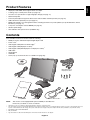
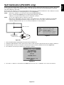
1
MultiSync PA242W
MultiSync PA272W
MultiSync PA302W
User’s Manual
Index
Warning, Caution ..........................................................................................................................English-1
Registration Information ...............................................................................................................English-2
Recommended use ......................................................................................................................English-3
Product Features ..........................................................................................................................English-5
Contents .......................................................................................................................................English-5
Quick Start....................................................................................................................................English-6
Controls ........................................................................................................................................English-11
Using the PICTURE MODE function ............................................................................................English-17
Advanced OSD.............................................................................................................................English-18
Specifications - PA242W ..............................................................................................................English-26
Specifications - PA272W ..............................................................................................................English-27
Specifications - PA302W ..............................................................................................................English-28
Features .......................................................................................................................................English-29
Troubleshooting ............................................................................................................................English-30
Using the Auto Brightness function ..............................................................................................English-32
Self Calibration (PA302W only) ....................................................................................................English-33
White Point Matching/Copy (PA302W only) .................................................................................English-35
Manufacturer’s Recycling and Energy Information.......................................................................English-37
TO PREVENT FIRE OR SHOCK HAZARDS, DO NOT EXPOSE THIS UNIT TO RAIN OR MOISTURE. ALSO, DO NOT
USE THIS UNIT’S POLARIZED PLUG WITH AN EXTENSION CORD RECEPTACLE OR OTHER OUTLETS UNLESS THE
PRONGS CAN BE FULLY INSERTED.
REFRAIN FROM OPENING THE CABINET AS THERE ARE HIGH VOLTAGE COMPONENTS INSIDE. REFER
SERVICING TO QUALIFIED SERVICE PERSONNEL.
CAUTION
CAUTION:
TO REDUCE THE RISK OF ELECTRIC SHOCK, MAKE SURE POWER CORD IS UNPLUGGED
FROM WALL SOCKET. TO FULLY DISENGAGE THE POWER TO THE UNIT, PLEASE DISCONNECT
THE POWER CORD FROM THE AC OUTLET.DO NOT REMOVE COVER (OR BACK). NO USER
SERVICEABLE PARTS INSIDE. REFER SERVICING TO QUALIFIED SERVICE PERSONNEL.
This symbol warns user that uninsulated voltage within the unit may have sufficient magnitude to cause
electric shock. Therefore, it is dangerous to make any kind of contact with any part inside this unit.
This symbol alerts the user that important literature concerning the operation and maintenance of this unit
has been included. Therefore, it should be read carefully in order to avoid any problems.
CAUTION: Please use the power cord provided with this display in accordance with the table below. If a power cord is not
supplied with this equipment, please contact your supplier. For all other cases, please use a power cord that matches the
AC voltage of the power outlet and has been approved by and complies with the safety standard of your particular country.
North America
European
Continental
U.K.
Chinese
Japanese
Country
U.S.A./Canada
EU (except U.K.)
U.K.
China
Japan
Voltage
120*
230
230
220
100
Plug Type
Plug Shape
* When operating the monitor with its AC 125-240V power supply, use a power supply cord that matches the power supply
voltage of the AC power outlet being used.
NOTE:
This product can only be serviced in the country where it was purchased.
Windows is a registered trademark of Microsoft Corporation.
NEC is a registered trademark of NEC Corporation.
ErgoDesign is a registered trademark of NEC Display Solutions, Ltd. in Austria, Benelux, Denmark, France,
Germany, Italy, Norway, Spain, Sweden, U.K.
All other brands and product names are trademarks or registered trademarks of their respective owners.
DisplayPort and DisplayPort Compliance Logo are trademarks owned by the Video Electronics Standards
Association.
HDMI, the HDMI logo and High-Definition Multimedia Interface are trademarks or registered trademarks of HDMI Licensing LLC
in the United States and other countries.
•
The intended primary use of this product is as an Information Technical Equipment in an office or domestic environment.
•
The product is intended to be connected to a computer and is not intended for the display of television broadcast signals.
English-1
English
WARNING
Registration Information
Canadian Department of Communications Compliance Statement
This Class B digital apparatus complies with Canadian ICES-003.
Cet appareil numerique de la classe B est conforme a la norme NMB-003 du Canada.
C-UL: Bears the C-UL Mark and is in compliance with Canadian Safety Regulations according to CAN/CSA C22.2 No. 60950-1.
FCC Information
1.
Use the attached specified cables with the MultiSync PA242W/MultiSync PA272W/MultiSync PA302W monitor so as not
to interfere with radio and television reception.
(1)
The power supply cord you use must have been approved by and comply with the safety standards of U.S.A.,
and meet the following condition.
Power supply cord
Length
Plug shape
Non shield type, 3-conductor
2.0 m
U.S.A
(2)
2.
Please use the supplied shielded video signal cable.
Use of other cables and adapters may cause interference with radio and television reception.
This equipment has been tested and found to comply with the limits for a Class B digital device, pursuant to part 15 of
the FCC Rules. These limits are designed to provide reasonable protection against harmful interference in a residential
installation. This equipment generates, uses, and can radiate radio frequency energy, and, if not installed and used
in accordance with the instructions, may cause harmful interference to radio communications. However, there is no
guarantee that interference will not occur in a particular installation. If this equipment does cause harmful interference to
radio or television reception, which can be determined by turning the equipment off and on, the user is encouraged to try
to correct the interference by one or more of the following measures:
•
Reorient or relocate the receiving antenna.
•
Increase the separation between the equipment and receiver.
•
Connect the equipment into an outlet on a circuit different from that to which the receiver is connected.
•
Consult your dealer or an experienced radio/TV technician for help.
If necessary, the user should contact the dealer or an experienced radio/television technician for additional suggestions.
The user may find the following booklet, prepared by the Federal Communications Commission, helpful: “How to Identify
and Resolve Radio-TV Interference Problems.” This booklet is available from the U.S. Government Printing Office,
Washington, D.C., 20402, Stock No. 004-000-00345-4.
Declaration of Conformity
This device complies with Part 15 of FCC Rules. Operation is subject to the following two conditions. (1) This device may not
cause harmful interference, and (2) this device must accept any interference received, including interference that may cause
undesired operation.
U.S. Responsible Party: NEC Display Solutions of America, Inc.
Address:
500 Park Boulevard, Suite 1100
Itasca, Illinois 60143
Tel. No.:
(630) 467-3000
Type of Product:
Display Monitor
Equipment Classification: Class B Peripheral
Model:
MultiSync PA242W (PA242W)
MultiSync PA242W (PA242W-BK)
MultiSync PA272W (PA272W)
MultiSync PA272W (PA272W-BK)
MultiSync PA302W (PA302W)
MultiSync PA302W (PA302W-BK)
We hereby declare that the equipment specified above conforms
to the technical standards as specified in the FCC Rules.
English-2
English
Recommended use
Safety Precautions and Maintenance
FOR OPTIMUM PERFORMANCE, PLEASE NOTE
THE FOLLOWING WHEN SETTING UP AND
USING THE LCD COLOR MONITOR:
•
DO NOT OPEN THE MONITOR. There are no user serviceable parts inside and opening or removing covers may expose
you to dangerous shock hazards or other risks. Refer all servicing to qualified service personnel.
•
Do not spill any liquids into the cabinet or use your monitor near water.
•
Do not insert objects of any kind into the cabinet slots, as they may touch dangerous voltage points, which can be harmful or
fatal or may cause electric shock, fire or equipment failure.
•
Do not place any heavy objects on the power cord. Damage to the cord may cause shock or fire.
•
Do not place this product on a sloping or unstable cart, stand or table, as the monitor may fall, causing serious damage to
the monitor.
•
The power supply cord you use must have been approved by and comply with the safety standards of your country.
(Type H05VV-F 3G 1mm2 should be used in Europe).
•
In UK, use a BS-approved power cord with molded plug having a black (5A) fuse installed for use with this monitor.
•
Do not place any objects onto the monitor and do not use the monitor outdoors.
•
Do not bend power cord.
•
Do not use monitor in high temperatured, humid, dusty, or oily areas.
•
Do not cover vent on monitor.
•
Vibration can damage the backlight. Do not install where the monitor will be exposed to continual vibration.
•
If monitor or glass is broken, do not come in contact with the liquid crystal and handle with care.
•
To prevent damage to the LCD monitor caused by tipping over due to earthquakes or other shocks, make sure to install the
monitor in a stable location and take measures to prevent falling.
Immediately turn off the power, unplug your monitor from the wall outlet and move to a safe location then refer servicing to
qualified service personnel under the following conditions. If the monitor is used in this condition, the monitor may cause fall, fire
and electric shock:
•
If the monitor stand has been cracked or peeled.
•
If the monitor has been wobbled.
•
If the monitor has an unusual odor.
•
When the power supply cord or plug is damaged.
•
If liquid has been spilled, or objects have fallen into the monitor.
•
If the monitor has been exposed to rain or water.
•
If the monitor has been dropped or the cabinet damaged.
•
If the monitor does not operate normally by following operating instructions.
CAUTION
•
Allow adequate ventilation around the monitor so that heat can properly dissipate. Do not block ventilated
openings or place the monitor near a radiator or other heat sources. Do not put anything on top of monitor.
•
The power cable connector is the primary means of detaching the system from the power supply.
The monitor should be installed close to a power outlet which is easily accessible.
•
Handle with care when transporting. Save packaging for transporting.
•
Do not touch LCD panel surface while transporting, mounting and setting.
Applying pressure on the LCD panel can cause serious damage.
•
The monitor must be installed or carried by two or more people (PA302W only).
•
Carry the monitor holding the built-in handle and bottom frames of the monitor
(PA302W only).
•
Do not carry holding only the stand (PA302W only).
PA302W only:
Image Persistence: Image persistence is when a residual or “ghost” image of a previous image remains visible on the screen.
Unlike CRT monitors, LCD monitors’ image persistence is not permanent, but constant images being displayed for a long period
of time should be avoided.
To alleviate image persistence, turn off the monitor for as long as the previous image was displayed. For example, if an image
was on the monitor for one hour and a residual image remains, the monitor should be turned off for one hour to erase the image.
NOTE: As with all personal display devices, NEC DISPLAY SOLUTIONS recommends using a moving screen saver at regular
intervals whenever the screen is idle or turning off the monitor when not in use.
English-3
CORRECT PLACEMENT AND ADJUSTMENT OF THE MONITOR CAN
REDUCE EYE, SHOULDER AND NECK FATIGUE. CHECK THE
FOLLOWING WHEN YOU POSITION THE MONITOR:
•
For optimum performance, allow 20 minutes for the display to warm up.
•
Adjust the monitor height so that the top of the screen is at or slightly below eye level.
Your eyes should look slightly downward when viewing the middle of the screen.
•
Position your monitor no closer than 40 cm (15.75 inches) and no further away than
70 cm (27.56 inches) from your eyes. The optimal distance is 50 cm (19.69 inches).
•
Rest your eyes periodically by focusing on an object at least 20 feet away. Blink often.
•
Position the monitor at a 90° angle to windows and other light sources to minimize glare
and reflections. Adjust the monitor tilt so that ceiling lights do not reflect on your screen.
•
If reflected light makes it hard for you to see your screen, use an anti-glare filter.
•
Clean the LCD monitor surface with a lint-free, non-abrasive cloth. Avoid using any
cleaning solution or glass cleaner!
•
Adjust the monitor’s brightness and contrast controls to enhance readability.
•
Use a document holder placed close to the screen.
•
Position whatever you are looking at most of the time (the screen or reference material) directly in front of you to minimize
turning your head while you are typing.
•
Avoid displaying fixed patterns on the monitor for long periods of time to avoid image persistence (after-image effects).
•
Get regular eye checkups.
Ergonomics
To realize the maximum ergonomics benefits, we recommend the following:
•
To avoid eye fatigue, adjust the brightness to a moderate setting. Place a sheet of white paper next to the LCD screen for
luminance reference.
•
Do not position the Contrast control to its maximum setting.
•
Use the preset Size and Position controls with standard signals.
•
Use the preset Color Setting.
•
Use non-interlaced signals with a vertical refresh rate of more than 60 Hz.
•
Do not use primary color blue on a dark background, as it is difficult to see and may produce eye fatigue due to insufficient
contrast.
Cleaning the LCD Panel
•
When the LCD is dusty, please gently wipe with a soft cloth.
•
Please do not rub the LCD panel with hard or coarse material.
•
Please do not apply pressure to the LCD surface.
•
Please do not use OA cleaner as it will cause deterioration or discoloration on the LCD surface.
Cleaning the Cabinet
•
Unplug the power supply
•
Gently wipe the cabinet with a soft cloth
•
To clean the cabinet, dampen the cloth with a neutral detergent and water, wipe the cabinet and follow with a dry cloth.
NOTE:
Many plastics are used on the surface of the cabinet. DO NOT clean with benzene, thinner, alkaline detergent,
alcoholic system detergent, glass cleaner, wax, polish cleaner, soap powder, or insecticide. Do not touch rubber or
vinyl to the cabinet for a long time. These types of fluids and fabrics can cause the paint to deteriorate, crack or peel.
For more detailed information on setting up a healthy work environment, write to the American National Standard for Human
Factors Engineering of Computer Workstations - ANSI/HFES 100-2007 - The Human Factors Society, Inc. P.O. Box 1369,
Santa Monica, California 90406.
English-4
English
Product Features
•
DisplayPort and HDMI, which support 10-bit color depth.
•
5-setting, easy-to-switch picture mode (see page 13).
•
Accurate color reproduction for high-end graphic design (see page 17).
•
Quick warmup time.
•
Picture-in-picture/picture-by-picture dual-screen mode includes real-time preview (see page 14).
•
USB hub with two upstream ports (see page 14).
•
MultiProfiler extends color management feature, including automatic ICC profile updates (ICC profile Emulation, Printer
Emulation) (see page 17).
•
Low power consumption via ECO MODE (see page 12).
•
Small footprint design.
•
Self calibration with optional sensor (PA302W only).
Contents
Your new NEC monitor box* should contain the following:
•
MultiSync monitor with tilt/swivel/pivot/height adjust stand
•
Power Cord*1
•
Video Signal Cable (DVI-D to DVI-D cable)*2
•
Video Signal Cable (DisplayPort cable)*3
•
Video Signal Cable (Mini DisplayPort to DisplayPort cable)*4
•
USB Cable
•
Setup Manual
•
CD-ROM*3
•
Screw (x 4) (to mount the monitor to a flexible arm (page 10))
CD-ROM*3
Mini-DisplayPort to
DisplayPort cable*4
Power Cord*1
Screws
Setup M
anual
Setup Manual
NOTE:
DVI-D to DVI-D cable*2
USB Cable
DisplayPort cable*3
This monitor can be equipped with optional “MultiSync Soundbar Pro”.
Please ask your dealer or check our website.
*
Remember to save your original box and packing material to transport or ship the monitor.
*1
Type and number of power cords included will depend on the where the LCD monitor is to be shipped. When more than one power cord is included, please use
a power cord that matches the AC voltage of the power outlet and has been approved by and complies with the safety standard of your particular country.
*2
Dual link DVI cable for PA272W/PA302W.
*3
Only for PA242W.
*4
Type and number of cables included will depend on the where the LCD monitor is to be shipped.
English-5
Quick Start
To connect the LCD monitor to your system, follow these instructions:
NOTE:
Make sure to read “Recommended Use” (page 3) before installation.
In order to display the maximum resolution, a video card that can output a resolution of 2560 x 1440 (PA272W) or
2560 x 1600 (PA302W) is needed.
PA302W only: The monitor must be installed or carried by two or more people.
1. Turn off the power to your computer.
2. For a PC or MAC with DVI digital output: Connect the DVI signal cable to the connector of the display card in your system
(Figure A.1). Tighten all screws.
For a PC with Analog output (PA242W only): Connect a 15-pin mini D-SUB to DVI-A signal cable (not included) to the
connector of the display card in your system (Figure A.2).
For a MAC (PA242W only): Connect a Macintosh cable adapter (not included) to the computer, then attach the 15-pin mini
D-SUB signal cable to the Macintosh cable adapter (Figure A.3).
NOTE:
Some Macintosh systems do not require a Macintosh cable adapter.
For a PC with DisplayPort output: Connect the DisplayPort cable to the connector of the display card in your system
(Figure A.4).
Figure A.1
NOTE:
Figure A.2
Macintosh Cable
Adapter
(not included)
Figure A.3
DisplayPort cable
Figure A.4
1. Please use a DisplayPort cable with a DisplayPort logo.
2. When removing the DisplayPort cable, hold down the top button to release the lock.
3. Height adjustment is locked by lock button. Place hand on top of the monitor to push down the screen to the lowest position.
Slide the lock button to unlock (Figure B.1).
NOTE:
Handle with care when unlocking stand.
Place hands on each side of the monitor to tilt the LCD panel 30-degree angle and lift up to the highest position.
Slide the cable cover up (Figure B.2).
NOTE:
Cable cover is not removable.
30° Tilt
Cable cover
Figure B.1
Figure B.2
English-6
NOTE:
Incorrect cable connections may result in irregular operation, damage display quality/components of LCD module
and/or shorten the module’s life.
30° Tilt
30° Tilt
USB downstream*2
USB downstream
Highest
Stand
Position
Highest
Stand
Position
A Type
A Type
B Type
USB downstream
USB downstream
USB upstream1
USB upstream1
USB upstream2
USB upstream2
DVI-D
DisplayPort
HDMI
DVI-D
Mini DisplayPort
DisplayPort
D-SUB
HDMI
B Type
Figure C.1a
Power cord
(PA242W only)
Power cord
Figure C.1
(PA272W/PA302W)
5. To keep the cables neatly organized, place them into the cable management system that is built into the stand.
Place the cables in the hooks firmly and evenly (Figure C.2 and Figure C.3).
6. Please check that you can still rotate, raise and lower the monitor screen when you have installed the cables.
D-SUB Cable*1
Power Cord
USB Cable
HDMI Cable*1
DisplayPort
Cable
DisplayPort
Cable*1
HDMI Cable*1
DVI Cable
DVI Cable
Mini DisplayPort
Cable
(PA242W only)
Power Cord
USB Cable*2
Figure C.2
(PA272W/PA302W)
Power Cord
Power Cord
D-SUB Cable*1
HDMI Cable*1
DisplayPort Cable
HDMI Cable*1
Mini DisplayPort
Cable
DVI Cable
DisplayPort Cable*1
USB Cable
USB Cable*2
DVI Cable
(PA242W only)
Figure C.3
1
* : Cable not included.
*2: Connect sensor to this port for self calibration (PA302W only).
English-7
(PA272W/PA302W)
English
4. Connect all cables to the appropriate connectors (Figure C.1). When using the USB cable, connect the B type connector
to the USB upstream port on the right back side of the monitor and the A type connector to the downstream port on the
computer (Figure C.1a). If using the cord from a USB device, plug into one of the downstream ports of the monitor.
7. Slide down the cable cover (Figure D.1).
8. Connect one end of the power cord to the AC inlet on the back of the monitor and the other end to the power outlet.
NOTE:
Please refer to Caution section of this manual for proper selection of AC power cord.
Figure D.1
9. Turn on the monitor with the front power button (Figure E.1) and the computer.
10. No Touch Auto Adjust automatically adjusts the monitor to optimal settings upon initial setup for most timings. For further
adjustments, use the following OSD controls:
• AUTO CONTRAST (Analog input only)*
• AUTO ADJUST (Analog input only)*
Refer to the Controls section of this User’s Manual for a full description of these OSD controls.
NOTE:
If you have any problems, please refer to the Troubleshooting section of this User’s Manual.
Power Button
Figure E.1
Raise and Lower Monitor Screen
The monitor may be raised or lowered in either Portrait or Landscape mode.
To raise or lower screen, place hands on each side of the monitor and lift or lower to the desired height (Figure RL.1).
NOTE:
Handle with care when raising or lowering the monitor screen.
Figure RL.1
* Only for PA242W.
English-8
Before rotating, the screen must be raised to the highest level and tilt to avoid knocking the screen on the desk or pinching your
fingers. Disconnect all cables.
To raise the screen, place hands on each side of the monitor and lift up to the highest position (Figure RL.1).
To rotate screen, place hands on each side of the monitor screen and turn clockwise from Landscape to Portrait or counterclockwise from Portrait to Landscape (Figure R.1).
To rotate OSD menu between landscape and portrait, refer to “Controls” section.
Figure R.1
Tilt
Grasp top and bottom sides of the monitor screen with your hands and adjust the tilt as desired (Figure TS.1).
Figure TS.1
NOTE:
Handle with care when tilting the monitor screen.
Swivel
Grasp both sides of the monitor screen with your hands and adjust the swivel as desired (Figure TS.2).
Figure TS.2
English-9
English
Screen Rotation
Flexible Arm Installation
This LCD monitor is designed for use with a flexible arm.
To prepare the monitor for alternate mounting purposes:
NOTE:
For PA302W, the monitor must be installed or moved by two or more people.
•
Follow the instructions provided by the manufacturer of the display mount.
•
To meet the safety requirements, the monitor must be mounted to an arm that supports the weight of the monitor.
See page 26-27-28 for details. Remove the monitor stand before mounting.
Remove Monitor Stand for Mounting
To prepare the monitor for alternate mounting purposes:
1. Disconnect all cables.
2. Place hands on each side of the monitor and lift up to the highest position.
3. Place monitor face down on a non-abrasive surface (Figure S.1).
4. Place one hand around the base and one hand on the Quick Release Lever.
Push and hold the Quick Release Lever in the direction indicated by the
arrows (Figure S.1).
5. Lift up the stand to unhook it from the monitor (Figure S.1).
The monitor can now be mounted using an alternate method.
Reverse process to reattach stand.
NOTE:
Handle with care when removing monitor stand.
Mount Flexible arm
Figure S.1
This LCD monitor is designed for use with a flexible arm.
1. Follow the instructions on how Remove Monitor Stand for Mounting to remove the stand.
2. Using the 4 screws from the stand removal and attach the arm to the monitor (Figure F.1).
100 mm
200 mm 100 mm
100 mm
100 mm
Weight of LCD assembly: 8.9 kg (PA272W)
10.7 kg (PA302W)
Weight of LCD assembly: 7.4 kg (PA242W)
Figure F.1
Caution: Use ONLY the screws (4 pcs) that are included or M4 sized screws (Length: thickness
of bracket and washer + 10-12 mm) when mounting to avoid damage to the monitor
and stand. To fulfil the safety requirements the monitor must be mounted to an arm
which guaranties the necessary stability under consideration of the weight of the
monitor. The LCD monitor should only be used with an approved arm (e.g. GS mark).
Unit
Mounting
Bracket
Washer
Screw
10-12 mm
NOTE:
Tighten all screws.
(recommended Fasten Force: 98 - 137N•cm)
English-10
Thickness
of bracket
and washer
OSD (On-Screen Display) control buttons on the front of the monitor
function as follows:
To access OSD menu, press the MENU button.
To change signal input, press the SELECT button.
NOTE:
OSD must be closed in order to change signal input.
8
7
Landscape
9
1
2
3
4
5
6
Portrait
1 AUTO DIMMING
SENSOR
Detects the level of ambient lighting allowing the monitor to make adjustments to various
settings resulting in a more comfortable viewing experience. Do not cover this sensor.
2 Power
Turns the monitor on and off.
3 LED
Indicates that the power is on.
Can be changed between blue and green in the Advanced OSD menu.
4 INPUT/SELECT
Enters the OSD Control menu. Enters OSD sub menus.
Changes the input source when not in the OSD Control menu.
Hold the button to show USB selection menu when not in the OSD Control menu*1.
NOTE: This USB selection setting back to the current setting by OSD menu when you change
input signal or turn off the monitor.
5 MENU/EXIT
Access OSD menu. Exits the OSD sub menu. Exits OSD Control menu.
6 LEFT/RIGHT
Navigates to the left or right through the OSD Control menu.
You can adjust the brightness directly, while the OSD menu is off*1.
7 UP/DOWN
Navigates up or down through the OSD Control menu.
Show PICTURE MODE menu when not in the OSD Control menu*1, *2.
8 RESET/PIP
Resets the OSD back to factory settings in the OSD control menu.
PIP can be selected when the OSD is not showing*3.
Hold the button to show ECO MODE menu while the OSD menu is off*1.
9 KEY GUIDE
The Key Guide appears on screen when the OSD control menu is accessed.
The Key Guide will rotate when the OSD control menu is rotated*.
* The “LEFT/RIGHT” and “UP/DOWN” buttons functionality is interchangeable depending on the orientation
(Landscape/Portrait) of the OSD.
*1 When HOTKEY function is OFF, this function is disabled.
*2 PICTURE MODE menu.
Press the UP/DOWN button to select PICTURE MODE. In PIP or PICTURE BY PICTURE mode, picture mode can
be selected for main and sub window independently by pressing LEFT/RIGHT button.
*3 PIP MODE menu.
Press the UP/DOWN button to select sub-window ON/OFF. Press the LEFT/RIGHT button to swap main window
and sub window.
SETTING OSD LANGUAGE
•
Use the control keys (LEFT/RIGHT or UP/DOWN or MENU) to access the “LANGUAGE SELECTION” menu.
•
Press the LEFT/RIGHT or UP/DOWN buttons to select the desired OSD language.
•
To exit from this OSD menu, press EXIT button.
NOTE:
Setting the OSD language is only necessary upon initial setup. The OSD language will stay the same until changed
by the user.
English-11
English
Controls
Brightness/Contrast Controls
BRIGHTNESS
Adjusts the overall image and background screen brightness.
NOTE:
The brightness level is adjusted using the backlight output.
The display will digitally compensate for low or high brightness levels.
If digital compensation occurs, the brightness value on the OSD will change to magenta.
NOTE:
The optimal display performance will be in the range where the OSD brightness value is black. When the
display cannot achieve the desired brightness, the numerical brightness value on the OSD will blink.
NOTE:
For low brightness settings, the display will automatically compensate by adjusting the screen contrast to
achieve the desired brightness. This will result in a reduced contrast ratio and the OSD indicator will change
to magenta.
NOTE:
For high brightness settings, the display will automatically compensate by turning down uniformity
compensation in order to achieve the desired brightness. The OSD indicator will change to magenta and this
may result in decreased uniformity.
CONTRAST (Analog input only)*
Adjusts the overall image and background screen brightness by input signal level.
NOTE:
It is recommended to use BRIGHTNESS to adjust screen brightness for lower power consumption and
improved image quality.
ECO MODE
Decreases the amount of power consumed by reducing the brightness level.
OFF: No function.
MODE1: Reduces the maximum possible brightness to about 200 cd/m2.
MODE2: Reduces the maximum possible brightness to about 100 cd/m2.
BLACK
Adjusts the black luminance.
When low settings are selected that cannot be displayed, the indicator on the OSD will turn magenta.
Auto Adjust (Analog input only)*
AUTO ADJUST
Automatically adjusts the Image Position and H. SIZE settings and FINE settings.
AUTO CONTRAST
Adjusts the image displayed for non-standard video inputs.
Image Controls
LEFT / RIGHT
Controls Horizontal Image Position within the display area of the LCD.
DOWN / UP
Controls Vertical Image Position within the display area of the LCD.
H.SIZE (V.SIZE) (Analog input only)*
Adjusts the horizontal size by increasing or decreasing this setting.
If the “AUTO ADJUST” function do not give you a satisfactory picture setting, a further tuning can be performed using
the “H.SIZE (or V.SIZE)” function (dot clock). For this a Moiré test pattern could be used. This function may alter the
width of the picture. Use LEFT/RIGHT Menu to center the image on the screen. If the H.SIZE (or V.SIZE) is wrongly
calibrated, the result would look like the left drawing. The image should be homogeneous.
When H.SIZE value is
wrong.
When H.SIZE value is
improved.
* Only for PA242W.
English-12
When H.SIZE value is
correct.
Improves focus, clarity and image stability by increasing or decreasing this setting.
If the “AUTO ADJUST” function and the “H.SIZE” function do not give you a satisfactory picture setting, a fine tuning
can be performed using the “FINE” function.
For this a Moiré test pattern could be used. If the FINE value is wrongly calibrated, the result would look like the left
drawing. The image should be homogeneous.
When FINE value is
wrong.
When FINE value is
correct.
AUTO FINE (Analog input only)*
This function automatically and periodically adjusts the “FINE” setting for change in signal condition.
This function adjusts approximately every 33 minutes.
EXPANSION
Sets the zoom method.
FULL: The image is expanded to full screen, regardless of the resolution.
ASPECT: The image is expanded without changing the aspect ratio.
OFF: The image is not expanded.
CUSTOM: Refer to the Advanced OSD menu for detailed instructions.
SHARPNESS
This function is digitally capable of keeping crisp image at any time. It is continuously adjustable to get as distinct or as
soft an image as your prefer and set independently by different timings.
Color Control Systems
PICTURE MODE
Change the Picture mode that is most suitable for the type of content that is shown. You can change up to 5 types.
See Advanced menu Tag1 PICTURE MODE (page 18) and “Using the PICTURE MODE function” (page 17) for more
information.
WHITE
Adjust the white temperature by NATIVE or increasing or decreasing this setting. A lower color temperature will make
the screen reddish and a higher color temperature will make the screen bluish. NATIVE is a default color temperature
of LCD panel. 6500K is recommended for general graphic design and 5000K is recommended for print matching.
ADJUST
HUE: Adjusts the hue of each color*1. The change in color will appear on screen and the menu color bars will show the
amount of adjustment.
OFFSET: Adjusts the color brightness of each color*1. Press “RIGHT” button and the color brightness increases.
SATURATION: Adjusts the color depth of each color*1. Press the “RIGHT” button and the color vividness increases.
WHITE (White Balance): If TEMPERATURE needs further adjustment, the individual R/G/B levels of the white point
can be adjusted. To adjust the R/G/B levels, CUSTOM must be showing as the TEMPERATURE selection.
ADVANCED SETTING
Shows ADVANCED MENU. See page 18 for detailed information. Set PICTURE MODE in detail in Advanced manual
Tag1.
* Only for PA242W.
*1: RED, YELLOW, GREEN, CYAN, BLUE and MAGENTA.
English-13
English
FINE (Analog input only)*
Tools
PIP MODE
Select PIP MODE, OFF/PIP/PICTURE BY PICTURE - ASPECT/PICTURE BY PICTURE - FULL.
You can select individual PICTURE MODE in each screen.
This display can display 2 inputs at a time.
OFF
PICTURE BY
PICTURE - ASPECT
*2, *5, *6
* * *
PIP
1, 3, 4
PICTURE BY
PICTURE - FULL
*2, *5, *6
MAIN IMAGE ROTATION: ON / SUB IMAGE ROTATION: ON
OFF
PIP
*3, *4
(PA242W)
PICTURE BY
PICTURE - ASPECT
*2, *5, *6
PICTURE BY
PICTURE - FULL
*2, *5, *6
(PA242W)
PIP INPUT
Selects the PIP input signal.
PIP LEFT/RIGHT
Controls the horizontal position of the Picture in Picture window in PIP mode.
PIP DOWN/UP
Controls the vertical position of the Picture in Picture window in PIP mode.
PIP SIZE
Selects the size of the sub-picture used in PIP mode.
USB SELECTION
Change USB upstream input associated with the current display input, 1 or 2. When connecting a computer to each
of the upstream ports, the monitor's USB downstream ports can be used by selecting this setting for the current input
signal.
You can change the active display and upstream USB port combination by using the Input button (see page 11).
You can set the USB selection for each input signals in Advanced menu (see page 22).
When using only one upstream port, the connected upstream port is used by default.
NOTE:
To avoid data loss, before changing USB upstream ports, ensure that no USB storage devices are in use by
the operating system of the computer attached to the USB upstream port.
VIDEO DETECT
Selects the method of video detection when more than one video input is connected.
FIRST: When current video input signal is not present, then the monitor searches for a video signal from the other
video input(s) port. If a video signal is present in another port, then the monitor switches the video source input port
to the new found video source automatically. The monitor will not look for other video signals while the current video
source is present.
LAST: When the monitor is displaying a signal from the current source and a new secondary source is supplied to
the monitor, then the monitor will automatically switch to the new video source. When current video input signal is not
present, then the monitor searches for a video signal from the other video input port(s). If the video signal is present in
another port, then the monitor switches the video source input port to the new found video source automatically.
NONE: The Monitor will not search the other video input port unless the monitor is turned on.
OFF TIMER
Monitor will automatically power-down when you have selected a pre-determined amount of time.
Before powering off, a message will appear on the screen asking if you want to delay the turn off time by 60 minutes.
Press any OSD button to delay the power-down time.
*1 PA272W/PA302W: Sub Window by DisplayPort or DVI is displayed on the left half of the display only.
Sub Window by HDMI or Mini-DisplayPort is displayed on the right half of the display only.
*2 PA272W/PA302W: When Main Window is Mini-DisplayPort or HDMI, it is impossible to select PICTURE BY PICTURE - ASPECT/FULL.
When PICTURE BY PICTURE - ASPECT/FULL is selected, it is impossible to change the Main Window Input to Mini-DisplayPort or HDMI. If DisplayPort or DVI signal
and PICTURE BY PICTURE - ASPECT/FULL are used, please connect to DisplayPort or DVI input for Main Window.
Print Emulation setting or “6 - AXIS ADJUST” setting by MultiProfiler will result the following cases depending on the setting conditions.
*3 Setting for only one screen: the setting result is reflected on the corresponding Window (Main or Sub).
Same setting for both screens: the setting result is reflected on both Main and Sub Windows.
*4 Individual setting for each screen: the setting result is reflected on Main Window only. Then Warning (6-AXIS SUB:OFF) will appear on screen.
*5 Individual setting for each screen: the setting result is reflected on Main Window only. Then Warning (6-AXIS SUB:OFF) will appear on screen (PA242W only).
*6 Setting for only one screen: the setting result is reflected on the corresponding Window (Main or Sub).
Same setting for both screens: the setting result is reflected on both Main and Sub Windows (PA242W only).
English-14
The Intelligent Power Manager allows the monitor to enter into a power saving mode after a period of inactivity.
The OFF MODE has four settings.
OFF: Monitor does not go into power save mode when the input signal is lost.
STANDARD: Monitor enters power save mode automatically when the input signal is lost.
ADVANCED: The signal detection circuit works always. Recovery time to normal mode is faster than STANDARD.
Power consumption is slightly higher than STANDARD.
NOTE:
When set to STANDARD, if the image does not reappear when the signal is restarted, please change the
setting to ADVANCED.
OPTION: Monitor enters power save mode automatically when the amount of surrounding light goes below the level that
is determined by the user. The level can be adjusted in OFF MODE SETTING in Tag 6 of the Advanced OSD menu.
When in power save mode, the LED on the front of the monitor blinks amber. While in power save mode, push any of
the front buttons, except for POWER and SELECT to return to normal.
When the amount of surrounding light returns to normal levels, the monitor will automatically return to normal mode.
MENU Tools
LANGUAGE
OSD control menus are available in nine languages.
OSD LEFT/RIGHT
You can choose where you would like the OSD control image to appear on your screen. Selecting OSD Location
allows you to manually adjust the position of the OSD control menu left or right.
OSD DOWN/UP
You can choose where you would like the OSD control image to appear on your screen. Selecting OSD Location
allows you to manually adjust the position of the OSD control menu Up or Down.
OSD TURN OFF
The OSD control menu will stay on as long as it is use. You can select how long the monitor waits after the last touch
of a button to shut off the OSD control menu. The preset choices are 10-120 seconds by 5-second increments.
OSD LOCK OUT
This control completely locks out access to all OSD control functions. When attempting to activate OSD controls while
in the Lock Out mode, a screen will appear indicating the OSD controls are locked out.
There are four types of OSD LOCK OUT:
OSD LOCK OUT with no control: To activate the OSD Lock Out function, press SELECT, then “RIGHT” button and
hold down simultaneously. To deactivate the OSD Lock Out, press SELECT, then “RIGHT” button and hold down
simultaneously while in the OSD menu. No controls can be adjusted while in the lock out mode.
OSD LOCK OUT with BRIGHTNESS (only) control: To activate the OSD Lock Out function, press SELECT, then
“DOWN” and “LEFT” buttons and hold down simultaneously. To deactivate the OSD Lock Out, press SELECT, then
“DOWN” and “LEFT” buttons and hold down simultaneously while in the OSD menu. BRIGHTNESS can be adjusted
while in this lock out mode.
CUSTOM: Refer to the Advanced OSD Menu.
OSD TRANSPARENCY
Adjusts the transparency of the OSD Menu.
OSD COLOR
Adjusts the color of the OSD Menu. “Tag window frame color”, “Item select color” and “Adjust window frame color” can
be changed to Red, Green, Blue, or Gray.
RESOLUTION NOTIFIER
The optimal resolution is 1920 x 1200 for PA242W, 2560 x 1440 for PA272W or 2560 x 1600 for PA302W. If ON is
selected, a message will appear on the screen after 30 seconds, notifying you that the resolution is not at 1920 x 1200
for PA242W, 2560 x 1440 for PA272W or 2560 x 1600 for PA302W.
HOT KEY
You can adjust the BRIGHTNESS directly. When this function is set to ON, you can adjust the brightness with “LEFT”
or “RIGHT”, while the OSD menu is off. The standard OSD can be accessed with the EXIT button. When this function
is set to OFF, some buttons are disabled (see page 11).
English-15
English
OFF MODE
FACTORY PRESET
Selecting FACTORY PRESET allows you to reset all OSD control settings (BRIGHTNESS, CONTRAST*1, ECOMODE,
BLACK, IMAGE CONTROL, COLOR CONTROL SYSTEM, SHARPNESS, PIP MODE, PIP INPUT, PIP LEFT/RIGHT,
PIP DOWN/UP, PIP SIZE, USB SELECTION, OFF TIMER, OFF MODE, OSD LEFT/RIGHT, OSD UP/DOWN, OSD
TURN OFF, OSD TRANSPARENCY) back to the factory settings. Individual settings can be reset by highlighting the
control to be reset and pressing the RESET button.
NOTE: If you want reset to include the Picture calibration settings and SELF COLOR CORRECTION settings,
please use FACTORY PRESET in Advanced OSD menu (see page 24).
ECO Information
CARBON SAVINGS: Displays the estimated carbon savings information in kg.
CARBON USAGE: Displays the estimated carbon usages information in kg.
This is the arithmetic estimation, not actual measurement value.
This estimation is based without any options.
COST SAVINGS: Displays the electricity cost savings in balance.
CARBON CONVERT SETTING: Adjusts the carbon footprint factor in the carbon saving calculation. This initial setting
is based on the OECD (2008 Edition).
CURRENCY SETTING: Displays electricity pricing in 6 currency units.
CURRENCY CONVERT SETTING: Displays electricity savings in kW/hour (US Currency is default).
NOTE: This model’s initial setting is “Currency = US$” and its Currency Convert setting = $0.11.
This setting can be changed by using the ECO information menu.
If you want to use the French setting, please refer to steps below:
1. Open menu by pressing the Menu button and select the ECO information menu using the “LEFT” or
“RIGHT” key.
2. Select CURRENCY SETTING item pressing the “UP” or “DOWN” key.
3. The French currency unit is Euro ( ). You can adjust currency setting to Euro icon ( ) from US dollar ($)
using the “LEFT” or “RIGHT” key in Current setting item.
4. Select CURRENCY CONVERT SETTING item using the “UP” or “DOWN” key.
This initial Euro ( ) setting is Germany of OECD (2007 Edition).
Please check receipt of French’s electricity prices or OECD data for French.
French of OECD (2007 Edition) was 0.12.
5. Adjust CURRENCY CONVERT SETTING item using the “LEFT” or “RIGHT” key.
Information
Provides information about the current resolution display (Main picture), current USB input setting and technical data
including the preset timing being used and the horizontal and vertical frequencies. Indicates the model and serial
numbers of your monitor.
OSD Warning
OSD Warning menus disappear with EXIT button.
NO SIGNAL: This function gives a warning when there is no Horizontal or Vertical Sync. After power is turned on or
when there is a change of input signal, the No Signal window will appear.
RESOLUTION NOTIFIER: This function warms if resolution other than the optimized resolution is used. After power is
turned on or when there is a change of input signal or the video signal doesn’t have proper resolution, the Resolution
Notifier window will open. This function can be disabled in the MENU Tools.
OUT OF RANGE: This function gives a recommendation of the optimized resolution and refresh rate. After the power
is turned on or there is a change of input signal or if the video signal doesn’t have proper timing, the Out Of Range
menu will appear.
INTERLACED SIGNALS ARE NOT SUPPORTED: This function gives a warning when the interlace signal is used.
While the image is visible, change the signal of the device from interlaced to progressive (non-interlaced).
See “No Picture” in Troubleshooting for detailed information.
If you need detailed information about the controls, please use the ADVANCED OSD menu.
*1: Only for PA242W.
English-16
Choose the Picture Mode that is most suitable for the type of content that is shown.
There are several types of mode (sRGB, Adobe®RGB, DCI, REC-Bt709, HIGH BRIGHT, FULL, DICOM, PROGRAMMABLE).
•
Each PICTURE MODE includes BRIGHTNESS, AUTO BRIGHTNESS, WHITE, Color Gamut, GAMMA, BLACK,
UNIFORMITY, COLOR VISION EMU, METAMERISM, RESPONSE IMPROVE, AMBIENT LIGHT COMP., 6-Axis ADJUST
settings. You can change these settings in Tag1 advanced menu.
The type of PRESET
PRESET
PURPOSE
sRGB
Standard color space used for the Internet, Windows operating systems and digital cameras. Recommended setting
for general color management.
Adobe®RGB
Factory setting. Provides a standard color space used in high-end graphics applications such as professional digital
still cameras and imaging.
eciRGB_v2
Provides a color space profile recommended by ECI (The European Color Initiative).
DCI
Color setting for digital cinema.
REC-Bt709
Color setting for High-definition television.
HIGH BRIGHT
Highest brightness setting.
FULL
Native display color gamut. Suitable for use with color managed applications. Use ICC color profile included in the
enclosed CD-ROM.
DICOM
Medical settings for X-ray imaging view. Setting that conforms to the DICOM standard for the Grayscale Standard
Display Function.
PROGRAMMABLE
For “MultiProfiler” software or the Hardware Calibration settings by NEC Display Solutions software (some OSD
settings are disabled).
NOTE:
- When the selected PICTURE MODE is different from your computer’s ICC color profile, you may experience
inaccurate color reproduction.
- MultiProfiler software, developed by NEC Display Solutions, is highly recommended to provide extended color
management features such as ICC profile Emulation and Printer Emulation. The latest MultiProfiler software is
available on the NEC Display Solutions website.
- When PICTURE MODE is locked, “PICTURE MODE IS LOCKED” appears on screen. To unlock PICTURE MODE
settings, press “SELECT” and “UP” buttons at the same time.
English-17
English
Using the PICTURE MODE function
Advanced OSD
If you need detailed information about the controls, please use the advanced menu.
There are 2 ways to access the advanced menu.
Method 1:
<To access the advanced menu>
• Press the Menu button to access OSD menu. Use the front buttons to move the cursor to the ADVANCED SETTING in Color
control systems. Press INPUT button to open the advanced OSD.
<To exit the advanced menu>
• Press the EXIT button.
Method 2:
<To access the advanced menu>
• Turn off the monitor.
•
Turn on the monitor by pushing the “POWER” and “INPUT/SELECT” button at the same time for at least one second
simultaneously. Then press the control buttons (EXIT, LEFT, RIGHT, UP, DOWN).
•
The Advanced OSD will appear.
This menu is larger than the normal OSD.
<To exit the advanced menu>
• Turn off and restart the monitor.
To make an adjustment, ensure that the tag is highlighted, then press “SELECT”.
To move to another tag, press “EXIT”, then press “LEFT” or “RIGHT” to highlight another tag.
Tag1
PICTURE MODE
Selects PICTURE MODE, one of 1 to 5.
PRESET
Sets PICTURE MODE PRESET from the type of PRESET (see page 17).
2
BRIGHTNESS*
Adjusts the overall image and screen background brightness.
Press “LEFT” or “RIGHT” to adjust.
WHITE
Adjusts the white color by temperature or xy setting. A lower color temperature will make
the screen reddish and a higher color temperature will make the screen bluish. A stronger
x makes the screen reddish, a stronger y makes it greenish and weak xy makes it a
bluish white.
*2 This item does not reset by FACTORY PRESET (Tag7), when the AUTO BRIGHTNESS is set to “ON”.
English-18
Allows you to manually select the brightness level of grayscale. There are five selections:
sRGB, L Star, DICOM, PROGRAMMABLE and CUSTOM. We recommend to show a
grayscale image on screen while adjusting gamma.
sRGB: GAMMA setting for sRGB.
L Star: GAMMA setting for eciRGB_v2 and Lab color space.
DICOM: DICOM GSDF (Grayscale Standard Display Function) is typically used for
medical imaging.
PROGRAMMABLE: The brightness of grayscale can be changed to your preference
by downloading the application software. You can select this when PICTURE MODE is
PROGRAMMABLE. This function could not select on Advanced OSD menu.
CUSTOM: CUSTOM VALUE can be adjusted when CUSTOM is selected as the GAMMA
SELECTION setting.
CUSTOM VALUE: The gamma value is selected from the range of 0.5 to 4.0 by 0.1 steps.
BLACK
Adjusts the black luminance. When the selected settings are too low to be displayed,
the indicator on the OSD will turn magenta.
RED
GREEN
BLUE
Adjusts color gamut. When the selected settings are outside of the LCD gamut, the
indicator on the OSD will turn magenta.
COLOR VISION EMU
Previews various typical human vision deficiencies and is useful for evaluating how
people who have such deficiencies will perceive colors. This preview is available in four
modes: Types P (Protanopia), D (Deutanopia) and T (Tritanopia) emulate color vision
dichromacy, and Grayscale can be used for evaluating contrast legibility.
NOTE: Depending on the vision of the user, including those with color vision deficiency,
there will be a variation in how the screen's color is seen and experienced.
A simulation is used to illustrate the view of those with a color vision deficiency. It is
not their actual view. The simulation is a reproduction of those with a strong color
vision mode of type P, type D or type T. People with a slight color vision deficiency will
experience little to no difference compared to those with normal color vision.
English-19
English
GAMMA
Tag2
Tag3
UNIFORMITY
This function electronically compensates for the slight variations in the white uniformity
level as well as for deviations in color that may occur throughout the display area of
the screen. These variations are characteristic of LCD panel technology. This function
improves the color and evens out the luminance uniformity of the display.
NOTE: Using the UNIFORMITY feature does reduce the overall peak luminance of the
display. If greater luminance is desired over the uniform performance of the display,
then UNIFORMITY should be turned off. A higher number produces a better effect, but
may also reduce CONTRAST RATIO. When BRIGHTNESS is shown in magenta, the
UNIFORMITY setting is automatically reduced.
SHARPNESS
This is a digital capability for keeping a crisp image at all signal timings. It continuously
adjusts to maintain as distinct or as soft image as you prefer, and is set independently
according to different timings. Press “LEFT” or “RIGHT” to adjust.
RESPONSE
IMPROVE
Turns the Response Improve function on or off. Response Improve may reduce blurring
that occurs in some moving images.
ECO MODE
Decreases the amount of power consumed by reducing the brightness level.
OFF: No function.
MODE1: Decreases the maximum possible brightness up to about 200 cd/m2.
MODE2: Decreases the maximum possible brightness up to about 100 cd/m2.
AUTO BRIGHTNESS
AUTO BRIGHTNESS has two settings. “OFF” is recommended for best color reproduction.
OFF: No function.
ON: Adjusts the brightness automatically, by detecting the brightness level of your
environment and adjusting the monitor with the best BRIGHTNESS setting.
Please refer to Page 32 for full “Auto Brightness” information.
Note: Do not cover environmental brightness sensor (AUTO DIMMING SENSOR).
METAMERISM
Improves the white point color matching when the display used side-by-side with a
standard gamut display monitor. This feature compensates for the way the human eye
perceives colors slightly differently compared to the scientific instrument used to adjust
the display during calibration.
AMBIENT LIGHT
COMP.
Luminance setting depends on ambient light compensation.
Mostly affects black reproduction.
NOTE: AUTO DIMMING SENSOR measures ambient brightness when power is on and
affects image and color quality settings.
NOTE: Do not cover environmental brightness sensor (AUTO DIMMING SENSOR).
(6 - AXIS ADJUST)
HUE: Adjusts the hue of each color*1. The change in color will appear on screen and the
menu color bars will show the amount of adjustment.
SATURATION: Adjusts the color depth of each color*1. Press the “RIGHT” button and the
color vividness increases.
OFFSET: Adjusts the color brightness of each color*1. Press “RIGHT” button and the
color Brightness increases.
*1: RED, YELLOW, GREEN, CYAN, BLUE and MAGENTA.
SHORTCUT
CUSTOM
You can select the PICTURE MODE which are displayed in PICTURE MODE shortcut
menu.
R-H.POSITION*
(Analog input only)
Adjusts the position of the red component of the image.
Press “LEFT” or “RIGHT” to adjust.
G-H.POSITION*
(Analog input only)
Adjusts the position of the green component of the image.
Press “LEFT” or “RIGHT” to adjust.
B-H.POSITION*
(Analog input only)
Adjusts the position of the blue component of the image.
Press “LEFT” or “RIGHT” to adjust.
R-FINE*
(Analog input only)
Adjusts the “FINE” setting of the RED component of the image.
Press “LEFT” or “RIGHT” to adjust.
G-FINE*
(Analog input only)
Adjusts the “FINE” setting of the GREEN component of the image.
Press “LEFT” or “RIGHT” to adjust.
B-FINE*
(Analog input only)
Adjusts the “FINE” setting of the BLUE component of the image.
Press “LEFT” or “RIGHT” to adjust.
R-SHARPNESS*
(Analog input only)
Adjusts the sharpness of the red component of the image.
Press “LEFT” or “RIGHT” to adjust.
G-SHARPNESS*
(Analog input only)
Adjusts the sharpness of the green component of the image.
Press “LEFT” or “RIGHT” to adjust.
B-SHARPNESS*
(Analog input only)
Adjusts the sharpness of the blue component of the image.
Press “LEFT” or “RIGHT” to adjust.
* Only for PA242W.
English-20
Compensates for image degradation caused by using a long cable.
A lower number produces less compensation.
Compensates for disturbed image caused by using a long DisplayPort cable.
DIGITAL LONG
CABLE (DP/Mini-DP*1 There are 2 possible settings, 1 and 2. Setting “2” produces a better result, but may
input only)
reduce display colors. The default setting is “1”.
Tag4
AUTO ADJUST*, *2
(Analog input only)
Automatically adjusts the Image Position and H.SIZE settings and FINE settings.
Press “SELECT” to activate Auto Adjustment. Please use test pattern, which is included
in the enclosed CD-ROM.
SIGNAL ADJUST*
(Analog input only)
Determines when the auto adjustment is activated automatically.
The choices are “SIMPLE” and “FULL”. Press “LEFT” or “RIGHT” to select.
H-size, Fine, H/V Position
Contrast
SIMPLE
O
X
FULL
O
O
O: Automatic Adjustment X: No Automatic Adjustment
NOTE: Automatic Adjustment does not work at resolutions less than 800x600 resolution.
AUTO ADJUST
LEVEL*
(Analog input only)
Determines the automatic adjustment level for AUTO ADJUST. The choices are “SIMPLE”,
“FULL” and “DETAIL”. Press “LEFT” or “RIGHT” to select. Refer to the below table.
Size, Fine, Position
Contrast
Black Level
Time
SIMPLE
O
X
X
1 second
FULL
O
O
X
1.5 seconds
DETAIL*
O
O
O
5 seconds
O: Automatic Adjustment
X: No Automatic Adjustment
* “DETAIL” activates automatic long cable (skew, peaking) adjustment.
A-NTAA SW*
(Analog input only)
The Advanced No Touch Auto Adjust function is able to recognize new signals even
when neither the resolution nor the refresh rate has changed. If several PCs are
connected to the monitor, and each transmit very similar (or even the same) signals in
terms of resolution and refresh rates, the monitor recognizes that there is a new signal
and automatically optimizes the picture without the need for any action on the part of the
user.
OFF: A-NTAA is disabled.
ON: If a change in signal is detected A-NTAA will adjust the monitor to the optimal
settings for the new signal. If no change in the signal is detected then A-NTAA does not
activate. The screen will be blank while the monitor optimizes the signal.
OPTION: Functions the same as ON, except that the screen does not go blank when the
monitor makes adjustments for changes in signal, allowing the monitor to display the new
signal faster. When using an external switching device to connect 2 or more PCs to the
monitor, using the ON or OPTION settings is suitable.
AUTO CONTRAST*, *2 Adjusts the image displayed for non-standard video inputs. Press “SELECT” to adjust.
(Analog input only)
Any adjustment requires the image to have white portions.
CONTRAST*
(Analog input only)
Adjusts the image brightness and contrast in relation to the background.
Press “LEFT” or “RIGHT” to adjust.
AUTO BLACK LEVEL*, *2 Automatically adjusts the black level. Any adjustment requires the image to have black
(Analog input only)
portions. Press “SELECT” to activate AUTO ADJUST.
Tag5
BLACK LEVEL*
(Analog input only)
Adjusts the RGB black level by input signal level.
VIDEO LEVEL
(HDMI input only)
NORMAL: For computer setting. Displays all input signals of 0-255 steps.
EXPAND: For audio-visual equipment setting. Expands input signals of 16-235 steps to
0-255 steps.
AUTO: Auto setting depending on the input signal.
H.POSITION
Controls Horizontal Image Position within the display area of the LCD.
Press “LEFT” or “RIGHT” to adjust.
V.POSITION
Controls Vertical Image Position within the display area of the LCD.
Press “LEFT” or “RIGHT” to adjust.
* Only for PA242W.
*1 Only for PA272W/PA302W.
*2 This item does not reset by FACTORY PRESET (Tag7).
English-21
English
DIGITAL LONG
CABLE
(DVI/HDMI input only)
Tag6
H.SIZE*
(Analog input only)
Adjusts the horizontal size of the screen.
If the “AUTO ADJUST” function do not give you a satisfactory picture setting, a further
tuning can be performed using the “H.SIZE (V.SIZE)” function (dot clock). For this a Moiré
test pattern could be used. This function may alter the width of the picture. Use LEFT/
RIGHT Menu to center the image on the screen. If the H.SIZE (V.SIZE) is incorrectly
calibrated, vertical bands will appear. The image should be homogeneous.
FINE*
(Analog input only)
Improve focus, clarity and image stability by increasing or decreasing this setting.
If the “AUTO ADJUST” function and the “H.SIZE” function do not give you a satisfactory
picture setting, a fine tuning can be performed using the “FINE” function. For this a Moiré
test pattern could be used. If the Fine value is incorrectly calibrated, horizontal lines will
appear on the display. The image should be homogeneous.
AUTO FINE*
(Analog input only)
This function automatically and periodically adjusts the “FINE” setting for change in signal
condition. This function adjusts approximately every 33 minutes.
H.RESOLUTION
Adjusts the horizontal size by increasing or decreasing the setting.
Press “RIGHT” button to expand the width of the image on the screen.
Press “LEFT” button to narrow the width of the image on the screen.
V.RESOLUTION
Adjusts the vertical size by increasing or decreasing the setting.
Press “RIGHT” button to expand the height of the image on the screen.
Press “LEFT” button to narrow the height of the image on the screen.
EXPANSION
Sets the zoom method.
FULL: The image is expanded to full screen, regardless of the resolution.
ASPECT: The image is expanded without changing the aspect ratio.
OFF: The image is not expanded.
CUSTOM: When CUSTOM is selected as the Expansion mode, it becomes possible to
adjust the H. ZOOM., V. ZOOM, and ZOOM POS.
OVER SCAN
(HDMI INPUT ONLY)
Some video formats may require different scanning modes in order to best display the image.
ON: Image size is larger than what can be displayed. The image edge will appear
cropped. Approximately 95% of the image will be shown on the screen.
OFF: Image size stays within the display area. The whole image is displayed on the screen.
AUTO: Auto setting.
SIDE BORDER
COLOR
Adjusts the side black bars color between black and white.
USB SELECTION
USB upstream port selection for DP/HDMI/DVI-D/D-SUB. When connecting a computer
to each of the upstream ports, the monitor’s USB downstream ports can be used by
selecting this setting for the current input signal. When using only one upstream port, the
connected upstream port is active.
You can change the active display and upstream USB port combination by using the
Input button (see page 11).
NOTE: To avoid data loss, before changing USB upstream ports, ensure that no USB
storage devices are in use by the operating system of the computer attached to the USB
upstream port.
VIDEO DETECT*2
Selects the method of video detection when more than one computer is connected.
Press “LEFT” or “RIGHT” to select.
FIRST: When current video input signal is not present, then the monitor searches for a
video signal from the other video input port(s). If the video signal is present in another
port, then the monitor switches the video source input port to the new found video source
automatically. The monitor will not look for other video signals while the current video
source is present.
LAST: When the monitor is displaying a signal from the current source and a new
secondary source is supplied to the monitor, then the monitor will automatically switch to
the new video source. When current video input signal is not present, then the monitor
searches for a video signal from the other video input port(s). If the video signal is
present in another port, then the monitor switches the video source input port to the new
found video source automatically.
NONE: The Monitor will not search the other video input port unless the monitor is
turned on.
OFF TIMER
Monitor will automatically turn off after the preset time period from power on with the
ON/OFF function. When you select “ON”, press “SELECT” and “LEFT” or “RIGHT” to adjust.
Before powering off, a message will appear on the screen asking the user if they want to
delay the turn off time by 60 minutes. Press any OSD button to delay the turn off time.
* Only for PA242W.
*2 This item does not reset by FACTORY PRESET (Tag7).
English-22
ON: Monitor automatically changes to OFF mode after 2 hours of continuous no-video
signal.
OFF: Monitor will not automatically change to OFF mode when no video signal is
connected.
OFF MODE
The Intelligent Power Manager allows the monitor to enter into a power saving mode after
a period of inactivity. The OFF MODE has four settings.
OFF: Monitor does not go into power save mode when the input signal is lost.
STANDARD: Monitor enters power save mode automatically when the input signal is lost.
ADVANCED: The signal detection circuit works always. Recovery time to normal mode is
faster than STANDARD. Power consumption is higher than STANDARD.
NOTE: When set to STANDARD, if the image does not reappear when the signal is
restarted, please change the setting to ADVANCED.
OPTION: Monitor enters power save mode automatically when the amount of
surrounding light goes below the level that is determined by the user.
OFF MODE SETTING Adjusts the ILLUMINANCE value for OFF MODE. Shows illuminance.
LED BRIGHTNESS*2
LED COLOR*
Tag7
LANGUAGE*
2
2
Controls the brightness of the power LED on the monitor.
Toggles the power LED on the front between blue or green.
OSD control menus are available in nine languages. Press “LEFT” or “RIGHT” to select.
OSD H.POSITION
You can choose where you would like the OSD control image to appear on your screen.
Selecting OSD Location allows you to manually adjust the position of the OSD control
menu left or right.
OSD V.POSITION
You can choose where you would like the OSD control image to appear on your screen.
Selecting OSD Location allows you to manually adjust the position of the OSD control
menu up or down.
OSD TURN OFF
The OSD control menu will stay on as long as it is use. You can select how long the
monitor waits after the last touch of a button to shut off the OSD control menu.
The preset choices are 10-120 seconds in 5 second increments.
OSD LOCK OUT*2
This control completely locks out access to all OSD control functions. When attempting
to activate OSD controls while in the Lock Out mode, a screen will appear indicating the
OSD controls are locked out.
There are three types of OSD LOCK OUT:
OSD LOCK OUT with no control: To activate the OSD Lock Out function, press SELECT,
then “RIGHT” button and hold down simultaneously. To deactivate the OSD Lock Out,
press SELECT, then “RIGHT” button and hold down simultaneously while in the OSD
menu. No controls can be adjusted while in the lock out mode.
OSD LOCK OUT with BRIGHTNESS (only) control: To activate the OSD Lock
Out function, press SELECT, then “DOWN” and “LEFT” buttons and hold down
simultaneously. To deactivate the OSD Lock Out, press SELECT, then “DOWN” and
“LEFT” buttons and hold down simultaneously while in the OSD menu. BRIGHTNESS
can be adjusted while in the lock out mode.
CUSTOM: Press RESET and EXIT to enter the CUSTOM Menu. Select ENABLE or
DISABLE for POWER KEY, INPUT SEL, HOT KEY (BRIGHTNESS), PICTURE MODE,
WARNING (RESOLUTION NOTIFIER/OSD LOCK OUT). To Deactivate the OSD Lock
Out function, press RESET and EXIT to bring up the LOCK OUT warning.
Press SELECT, SELECT, <, >, <, >, EXIT.
OSD TRANSPARENCY Adjusts the transparency of the OSD MENU.
OSD COLOR*2
“Tag window frame color”, “Item select color” & ”Adjust Window frame color” can be
changed.
BOOT LOGO*2
The NEC logo is briefly displayed after the monitor is powered on. This feature can be
turned on or off in the OSD.
Note: If the “EXIT” button is kept pressed while NEC logo is displayed, the BOOT LOGO
menu will appear. It is possible to change the BOOT LOGO setting to OFF.
SIGNAL
INFORMATION*2
Signal information can be displayed in the corner of the screen.
Signal information is either “ON/OFF”.
RESOLUTION
NOTIFIER*2
The optimal resolution is 1920 x 1200 for PA242W, 2560 x 1440 for PA272W or
2560 x 1600 for PA302W. If ON is selected, a message will appear on the screen after
30 seconds, notifying you that the resolution is not set to 1920 x 1200 for PA242W,
2560 x 1440 for PA272W or 2560 x 1600 for PA302W.
Press “LEFT” or “RIGHT” to select.
*2 This item does not reset by FACTORY PRESET (Tag7).
English-23
English
POWER SAVE
TIMER
Tag8
Tag9*
(Analog
input only)
HOT KEY*2
When this function is activated; the brightness of the monitor can be adjusted without
entering the OSD menu by using the front buttons.
The “LEFT” or “RIGHT” buttons adjust the brightness level.
When this function is set to OFF, some buttons are disabled. See page 11.
FACTORY PRESET*2
Selecting FACTORY PRESET allows you to reset all OSD control settings back to the
factory settings. Highlighting the control to be reset and pressing the RESET button can
reset individual settings.
PIP MODE
Selects PIP MODE, OFF/PIP/PICTURE BY PICTURE - ASPECT/PICTURE BY
PICTURE - FULL. See page 14.
PIP INPUT
Selects the PIP input signal.
PIP LEFT/RIGHT
When you select “PIP” in PIP MODE, you can control horizontal position of PIP display area.
PIP DOWN/UP
When you select “PIP” in PIP MODE, you can control vertical position of PIP display area.
PIP SIZE
Selects the size of the sub-picture used in PIP MODE.
BLANK SIGNAL SKIP
Skip no signal inputs when you change input signal with INPUT button.
OSD ROTATION
AUTO: The OSD rotates automatically when the monitor is rotated. OSD ROTATION is
set to AUTO by default.
LANDSCAPE: Display the OSD with landscape mode.
PORTRAIT: Display the OSD with portrait mode.
MAIN IMAGE
ROTATION
AUTO: The main window image automatically rotates according to the orientation of the
display.
OFF: The main window image is not rotated. MAIN IMAGE ROTATION is set to OFF by
default.
ON: The main window image always rotated.
Note: For PA272W/PA302W, this function is effective only if PICTURE BY PICTUREASPECT or PICTURE BY PICTURE-FULL.
SUB IMAGE
ROTATION
AUTO: The sub window image automatically rotates according to the orientation of the
display.
OFF: The sub window image is not rotated. SUB IMAGE ROTATION is set to OFF by
default.
ON: The sub window image always rotated.
DDC/CI
DDC/CI ENABLE/DISABLE: Turns on or off the two way communication and control with
connected PC by video cable.
NOTE: Set DDC/CI to ENABLE when using hardware calibration software like
MultiProfiler over DisplayPort, DVI or VGA.
SCREEN SAVER
Use the SCREEN SAVER to reduce the risk of image persistence.
MOTION (Default OFF): Screen image moves periodically in 4 directions in order to
reduce the risk of image retention.
Timing for MOTION can be set so the screen image moves in intervals from every
10 to 900 seconds. Timing is set in 10-second increments.
OPTION (Default REDUCED): There are two optional selections.
REDUCED: Screen image is reduced to 95% size and is moved periodically in
4 directions. Screen may appear slightly less sharp than normal. The full image appears
on the display.
NOTE: Some input signals may not be supported by REDUCED.
FULL: Screen image is set to FULL and is moved periodically in 4 directions. Screen
image goes outside of the display area in the direction that it shifts so that a portion of the
image may appear to be cut off.
NOTE: SCREEN SAVER works when ENABLE is OFF in TILE MATRIX and PIP MODE
is OFF.
INPUT SETTING*2
Video Band Width: Reduce the visual “noise” level of the input signal. It is strong
ineffective, so that a number becomes small. Press “LEFT” or “RIGHT” to select.
Sync Threshold: Adjusts the slice level of a synchronization signal. Press “SELECT” to
move the adjustment menu. Adjusts the sensitivity of the separate or composite input
signals.
Try this option if the FINE adjustment does not successfully eliminate the noise.
Clamp position: Operating your monitor at a non-standard timing may cause images to
appear darker than normal or have color distortion. Use of the Clamp position control will
adjust images to their normal state.
* Only for PA242W.
*2 This item does not reset by FACTORY PRESET (Tag7).
English-24
TILE MATRIX
The TILE MATRIX feature allows one image to be displayed over multiple screens. This
feature can be used with up to 25 monitors (5 vertical and 5 horizontal). Using TILE
MATRIX requires the PC output signal be sent through a distribution amplifier to each
individual monitor.
H MONITOR: Select the number of horizontal displays.
V MONITOR: Select the number of vertical displays.
MONITOR No: Select a position to expand the screen.
TILE COMP: Works in tandem with TILE MATRIX to compensate for the width of the tile
bezels in order to accurately display the image.
Tile Comp with 4 monitors (black area shows monitor frames):
monitor1
monitor2
monitor1
monitor2
monitor3
monitor4
monitor3
monitor4
Tile Comp OFF
Tile Comp ON
NOTE: TILE MATRIX works only when PIP MODE is OFF.
TagB
TagC
CARBON SAVINGS
Displays the estimated carbon savings information in kg.
CARBON USAGE
Displays the estimated carbon usages information in kg. This is the arithmetic estimation,
not actual measurement value. This estimation is based without any options.
COST SAVINGS
Displays the electricity cost savings in balance.
CARBON CONVERT
SETTING
Adjusts the carbon footprint factor in the carbon saving calculation. This initial setting is
based on the OECD (2008 Edition).
CURRENCY
SETTING*2
Displays electricity pricing (available in 6 currency units).
CURRENCY
CONVERT SETTING
Adjusts electricity prices-electric energy equivalent in the electrical rate saving
calculation.
HOURS RUNNING*2
Show total running time.
SELF COLOR
CORRECTION
Uses the internal color sensor to compensate for a natural color shift that occurs with
age.
STAND-ALONE
CALIBRATION*
Compensates for a typical LCD yellowish color shift due to long-term usage by optional USB
color sensor. See page 33. When you use this function, SELF COLOR CORRECTION is not
necessary.
INFORMATION*2
Provides information about the current display resolution. Technical data, including the preset
timing currently being used and the horizontal and vertical frequencies is also displayed.
* Only for PA302W.
*2 This item does not reset by FACTORY PRESET (Tag7).
English-25
English
TagA
Specifications - PA242W
Monitor Specifications
MultiSync PA242W
Notes
LCD Module
61.1 cm/24.1 inches
61.1 cm/24.1 inches
1920 x 1200
Active matrix; thin film transistor (TFT) liquid crystal
display (LCD); 0.270 mm dot pitch; 340 cd/m2 white
luminance; 1000:1 contrast ratio (typical).
Digital RGB
DisplayPort Complies with Standard V1.1a,
applicable to HDCP
Diagonal:
Viewable Image Size:
Native Resolution (Pixel Count):
Input Signal
DisplayPort:
DisplayPort Connector:
DVI:
Digital RGB
DVI (HDCP)
VGA:
15pin Mini D-sub:
DVI-D 24pin:
Analog RGB
Sync
0.7 Vp-p/75 ohm
Separate sync.TTL level Positive/Negative
Composite sync.TTL level Positive/Negative
HDMI:
HDMI Connector:
Digital RGB
HDMI (HDCP)
1,073,741,824 (DisplayPort/HDMI 10 bit)
16,777,216 (DVI)
Depends on display card used.
31.5 kHz to 93.8 kHz, 118.4 kHz*2 (Analog)
31.5 kHz to 91.1 kHz, 118.4 kHz*2 (Digital)
50 Hz to 85 Hz
Automatically
Automatically
Automatically
Display Colours
Synchronization Range
Horizontal:
Viewing Angle
Left/Right:
Up/Down:
Vertical:
±89° (CR > 10)
±89° (CR > 10)
Image Formation Time
8 ms (Gray to gray Typ)
Resolutions Supported (Some systems may
not support all modes listed).
640 x 480*1 at 60 Hz to 85 Hz
720 x 400*1 at 70 Hz to 85 Hz
800 x 600*1 at 56 Hz to 85 Hz
832 x 624*1 at 75 Hz
1024 x 768*1 at 60 Hz to 85 Hz
1280 x 960*1 at 60 Hz to 85 Hz
1280 x 1024*1 at 60 Hz to 85 Hz
1600 x 1200*1 at 60 Hz
NEC DISPLAY SOLUTIONS recommended resolution
1920 x 1200 at 60 Hz........................................... for optimal display performance.
1400 x 1050*1 at 60 Hz to 75 Hz
1400 x 900*1 at 60 Hz to 85 Hz
1600 x 1200*1 at 65 Hz to 75 Hz (Analog)
480P (720 x 480*1 at 60 Hz)
576P (720 x 576*1 at 60 Hz)
720P (1280 x 720*1 at 50 Hz to 60 Hz)
1080P (1920 x 1080*1 at 50 Hz to 60 Hz)
960 x 1200*1 at 60 Hz
1200 x 960*1 at 60 Hz
1200 x 1920 at 60 Hz
Active Display Area
518.4 mm/20.4 inches
324.0 mm/12.8 inches
324.0 mm/12.8 inches
518.4 mm/20.4 inches
USB Hub
Landscape: Horiz.:
Vert.:
Portrait: Horiz.:
Vert.:
I/F:
Port:
Load Current:
USB Specification Revision 2.0
Upstream 2
Downstream 3
Maximum 0.5A per port
Power Supply
AC 100-240 V ~ 50/60 Hz
Current Rating
0.84 - 0.38 A (with option)
Dimensions
Landscape:
Portrait:
Height Adjustment:
556.8 mm (W) x 378 - 528 mm (H) x 227.6 mm (D)
21.9 inches (W) x 14.9 - 20.8 inches (H) x 9.0 inches (D)
362.4 mm (W) x 572.4 - 625.2 mm (H) x 227.6 mm (D)
14.3 inches (W) x 22.5 - 24.6 inches (H) x 9.0 inches (D)
150 mm / 5.9 inches (Landscape orientation)
52.8 mm / 2.1 inches (Portrait orientation)
Weight
10.6 kg (23.4 lbs)
Environmental Considerations
Operating Temperature:
Humidity:
Altitude:
Storage Temperature:
Humidity:
Altitude:
5°C to 35°C/41°F to 95°F
20% to 80%
0 to 6,562 Feet/0 to 2,000 m
-10°C to 60°C/14°F to 140°F
10% to 85%
0 to 40,000 Feet/0 to 12,192 m
*1 Interpolated Resolutions: When resolutions are shown that are lower than the pixel count of the LCD module, text may appear different. This is normal and
necessary for all current flat panel technologies when displaying non-native resolutions full screen. In flat panel technologies, each dot on the screen is actually one
pixel, so to expand resolutions to full screen, an interpolation of the resolution must be done.
*2 1200 x 1920 resolution only.
NOTE:
Technical specifications are subject to change without notice.
English-26
Monitor Specifications
MultiSync PA272W
Notes
LCD Module
68.5 cm/27.0 inches
68.5 cm/27.0 inches
2560 x 1440
Active matrix; thin film transistor (TFT) liquid crystal
display (LCD); 0.233 mm dot pitch; 340 cd/m2 white
luminance; 1000:1 contrast ratio (typical).
DisplayPort Connector:
Mini-DisplayPort Connector:
Digital RGB
DisplayPort Complies with Standard V1.1a,
applicable to HDCP
DVI-D 24pin:
Digital RGB
DVI (HDCP)
HDMI Connector:
Digital RGB
HDMI (HDCP)
1,073,741,824 (DisplayPort/Mini-DisplayPort/
HDMI 10 bit)
16,777,216 (DVI)
Depends on display card used.
Automatically
Automatically
Diagonal:
Viewable Image Size:
Native Resolution (Pixel Count):
Input Signal
DisplayPort:
DVI:
HDMI:
Display Colours
Synchronization Range
Horizontal:
Vertical:
31.5 kHz to 93.9 kHz
50 Hz to 87 Hz
Viewing Angle
Left/Right:
Up/Down:
±89° (CR > 10)
±89° (CR > 10)
Image Formation Time
7 ms (Gray to gray Typ)
Resolutions Supported (Some systems may
not support all modes listed).
640 x 480*1 at 60 Hz to 85 Hz
720 x 350*1 at 70 Hz to 85 Hz
720 x 400*1 at 70 Hz to 85 Hz
800 x 600*1 at 56 Hz to 85 Hz
832 x 624*1 at 75 Hz
1024 x 768*1 at 60 Hz to 85 Hz
1152 x 864*1 at 70 Hz to 85 Hz
1152 x 870*1 at 75 Hz
1152 x 900*1 at 66 Hz
1280 x 960*1 at 60 Hz
1280 x 1024*1 at 60 Hz to 85 Hz
1400 x 1050*1 at 60 Hz to 75 Hz
1440 x 900*1 at 60 Hz to 85 Hz
1600 x 1200*1 at 60 Hz
1680 x 1050*1 at 60 Hz
1920 x 1200*1 at 60 Hz
1024 x 1280*1 at 60 Hz
1200 x 1920*1 at 60 Hz
2560 x 1440 at 60 Hz........................................... NEC DISPLAY SOLUTIONS cites recommended
480P (720 x 480*1 at 60 Hz)
resolution for optimal display performance.
576P (720 x 576*1 at 50 Hz)
1
720P (1280 x 720* at 50 Hz to 60 Hz)
1080P (1920 x 1080*1 at 50 Hz to 60 Hz)
Active Display Area
597 mm/23.5 inches
336 mm/13.2 inches
336 mm/13.2 inches
597 mm/23.5 inches
USB Hub
Landscape: Horiz.:
Vert.:
Portrait: Horiz.:
Vert.:
I/F:
Port:
Load Current:
USB Specification Revision 2.0
Upstream 2
Downstream 3
Maximum 0.5A per port
Power Supply
AC 100-240 V ~ 50/60 Hz
Current Rating
1.0 - 0.45 A (with option)
Dimensions
Landscape:
Portrait:
Height Adjustment:
640.4 mm (W) x 396.2 - 546.2 mm (H) x 235.5 mm (D)
25.2 inches (W) x 15.6 - 21.5 inches (H) x 9.3 inches (D)
378.6 mm (W) x 658.0 - 677.1 mm (H) x 235.5 mm (D)
14.9 inches (W) x 25.9 - 26.7 inches (H) x 9.3 inches (D)
150 mm / 5.9 inches (Landscape orientation)
19.1 mm / 0.8 inches (Portrait orientation)
Weight
12.9 kg (28.4 lbs)
Environmental Considerations
Operating Temperature:
Humidity:
Altitude:
Storage Temperature:
Humidity:
Altitude:
5°C to 35°C/41°F to 95°F
20% to 80%
0 to 10,000 Feet/0 to 3,048 m
-10°C to 60°C/14°F to 140°F
10% to 85%
0 to 40,000 Feet/0 to 12,192 m
*1 Interpolated Resolutions: When resolutions are shown that are lower than the pixel count of the LCD module, text may appear different. This is normal and
necessary for all current flat panel technologies when displaying non-native resolutions full screen. In flat panel technologies, each dot on the screen is actually one
pixel, so to expand resolutions to full screen, an interpolation of the resolution must be done.
NOTE:
Technical specifications are subject to change without notice.
English-27
English
Specifications - PA272W
Specifications - PA302W
Monitor Specifications
MultiSync PA302W
Notes
LCD Module
75.6 cm/29.8 inches
75.6 cm/29.8 inches
2560 x 1600
Active matrix; thin film transistor (TFT) liquid crystal
display (LCD); 0.251 mm dot pitch; 340 cd/m2 white
luminance; 1000:1 contrast ratio (typical).
DisplayPort Connector:
Mini-DisplayPort Connector:
Digital RGB
DisplayPort Complies with Standard V1.1a,
applicable to HDCP
DVI-D 24pin:
Digital RGB
DVI (HDCP)
HDMI Connector:
Digital RGB
HDMI (HDCP)
1,073,741,824 (DisplayPort/Mini-DisplayPort/
HDMI 10 bit)
16,777,216 (DVI)
Depends on display card used.
Automatically
Automatically
Diagonal:
Viewable Image Size:
Native Resolution (Pixel Count):
Input Signal
DisplayPort:
DVI:
HDMI:
Display Colours
Synchronization Range
Horizontal:
Vertical:
31.5 kHz to 98.7 kHz
30 Hz to 87 Hz
Viewing Angle
Left/Right:
Up/Down:
±89° (CR > 10)
±89° (CR > 10)
Image Formation Time
7 ms (Gray to gray Typ)
Resolutions Supported (Some systems may
not support all modes listed).
640 x 480*1 at 60 Hz to 85 Hz
720 x 350*1 at 70 Hz to 85 Hz
720 x 400*1 at 70 Hz to 85 Hz
800 x 600*1 at 56 Hz to 85 Hz
832 x 624*1 at 75 Hz
1024 x 768*1 at 60 Hz to 85 Hz
1152 x 864*1 at 70 Hz to 85 Hz
1152 x 870*1 at 75 Hz
1152 x 900*1 at 66 Hz
1280 x 960*1 at 60 Hz
1280 x 1024*1 at 60 Hz to 85 Hz
1400 x 1050*1 at 60 Hz to 75 Hz
1440 x 900*1 at 60 Hz to 85 Hz
1600 x 900*1 at 60 Hz
1600 x 1200*1 at 60 Hz
1680 x 1050*1 at 60 Hz
1920 x 1200*1 at 60 Hz
2048 x 1536*1 at 30 Hz
1024 x 1280*1 at 60 Hz
2560 x 1600 at 60 Hz........................................... NEC DISPLAY SOLUTIONS cites recommended
480P (720 x 480*1 at 60 Hz)
resolution for optimal display performance.
576P (720 x 576*1 at 50 Hz)
720P (1280 x 720*1 at 50 Hz to 60 Hz)
1080P (1920 x 1080*1 at 50 Hz to 60 Hz)
Active Display Area
641 mm/25.2 inches
401 mm/15.8 inches
401 mm/15.8 inches
641 mm/25.2 inches
USB Hub
Landscape: Horiz.:
Vert.:
Portrait: Horiz.:
Vert.:
I/F:
Port:
Load Current:
USB Specification Revision 2.0
Upstream 2
Downstream 3
Maximum 0.5A per port
Power Supply
AC 100-240 V ~ 50/60 Hz
Current Rating
1.1 - 0.51 A (with option)
Dimensions
Landscape:
Portrait:
Height Adjustment:
688.0 mm (W) x 466.4 - 616.4 mm (H) x 301.6 mm (D)
27.1 inches (W) x 18.4 - 24.3 inches (H) x 11.9 inches (D)
446.8 mm (W) x 707.1 - 737.0 mm (H) x 301.6 mm (D)
17.6 inches (W) x 27.8 - 29.0 inches (H) x 11.9 inches (D)
150 mm / 5.9 inches (Landscape orientation)
29.9 mm / 1.2 inches (Portrait orientation)
Weight
17 kg (37.5 lbs)
Environmental Considerations
Operating Temperature:
Humidity:
Altitude:
Storage Temperature:
Humidity:
Altitude:
5°C to 35°C/41°F to 95°F
20% to 80%
0 to 10,000 Feet/0 to 3,048 m
-10°C to 60°C/14°F to 140°F
10% to 85%
0 to 40,000 Feet/0 to 12,192 m
*1 Interpolated Resolutions: When resolutions are shown that are lower than the pixel count of the LCD module, text may appear different. This is normal and
necessary for all current flat panel technologies when displaying non-native resolutions full screen. In flat panel technologies, each dot on the screen is actually one
pixel, so to expand resolutions to full screen, an interpolation of the resolution must be done.
NOTE:
Technical specifications are subject to change without notice.
English-28
DisplayPort: DisplayPort is designed to be the future-ready, scalable solution for high performance digital display connectivity. It
enables the highest resolutions, the fastest refresh rates and deepest color depths over standard cables.
HDMI: HDMI is designed to be the future-ready, scalable solution for high performance digital display connectivity. It enables the highest
resolutions, the fastest refresh rates and deepest color depths over standard cables, especially for consumer audio/video equipment.
DFP (Digital Flat Panel): An all-digital interface for flat panel monitors which is signal compatible with DVI. As a DVI-based digital only
connection, only a simple adapter is necessary for compatibility between DFP and other DVI-based digital connectors such as DVI and
P&D.
P&D (Plug and Display): The VESA standard for digital flat panel monitor interfaces. It is more robust than DFP since it allows for other
options off a signal connector (options like USB, analog video and IEEE-1394-995). The VESA committee has recognized that DFP is a
subset of P&D. As a DVI-based connector (for the digital input pins), only a simple adapter is necessary for compatibility between P&D
and other DVI-based digital connector such as DVI and DFP.
Pivoting Stand: Allows users to adjust the monitor to the orientation that best fits their application, either Landscape orientation for
wide documents, or Portrait orientation for the ability to preview a full page on one screen at one time. The Portrait orientation is also
perfect for full screen video conferencing.
Reduced Footprint: Provides the ideal solution for environments with space constraints that still require superior image quality. The
monitor’s small footprint and low weight allow it to be moved or transported easily from one location to another.
Color Control Systems: Allow you to adjust the colors on your screen and customize the color accuracy of your monitor to a variety of
standards.
Natural Color Matrix: Combines Six-axis color control and the sRGB standard. Six-axis color control permits color adjustments via
six axes (R, G, B, C, M and Y) rather than through the three axes (R, G and B) previously available. The sRGB standard provides the
monitor with a uniform color profile. This assures that the colors displayed on the monitor are exactly the same as on the color printout
(with sRGB supporting operating system and sRGB printer). This allows you to adjust the colors on your screen and customise the color
accuracy of your monitor to a variety of standards.
OSD (On-Screen Display) Controls: Allow you to quickly and easily adjust all elements of your screen image via simple to use onscreen menus.
ErgoDesign Features: Enhanced human ergonomics to improve the working environment, protect the health of the user and save
money. Examples include OSD controls for quick and easy image adjustments, tilt base for preferred angle of vision, small footprint and
compliance with MPRII and TCO guidelines for lower emissions.
Plug and Play: The Microsoft® solution with the Windows® operating system facilitates setup and installation by allowing the monitor
to send its capabilities (such as screen size and resolutions supported) directly to your computer, automatically optimizing display
performance.
Intelligent Power Manager System: Provides innovative power-saving methods that allow the monitor to shift to a lower power
consumption level when on but not in use, saving two-thirds of your monitor energy costs, reducing emissions and lowering the air
conditioning costs of the workplace.
Multiple Frequency Technology: Automatically adjusts monitor to the display card’s scanning frequency, thus displaying the resolution
required.
FullScan Capability: Allows you to use the entire screen area in most resolutions, significantly expanding image size.
Wide Viewing Angle Technology: Allows you to be able to see the monitor from any angle (178°) from any orientation — Portrait or
Landscape. Provides full 178° viewing angles either up, down, left or right.
VESA Standard Mounting Interface: Allows users to connect your MultiSync monitor to any VESA standard third party mounting arm
or bracket.
Visual Controller: Is a ground-breaking software family, developed by NEC Display Solutions, providing intuitive access to all monitor
setting controls and remote diagnosis via the Windows interface, based upon the VESA standard, DDC/CI. Using a standard VGA or
DVI signal cable, Visual Controller can either benefit single users or, with Visual Controller Administrator, can reduce the Total Cost of
Ownership through remote network-wide maintenance, diagnosis and asset-reporting.
No Touch Auto Adjust (Analog input only)*: Automatically adjusts the monitor to optimal settings upon initial setup.
sRGB Color Control: A new optimized color management standard which allows for color matching on computer displays and other
peripherals. The sRGB, which is based on the calibrated color space, allows for optimal color representation and backward compatibility
with other common color standards.
UNIFORMITY: This feature compensates for slight variations in the white uniformity level that may occur on the screen and improves
the color and evens out the luminance uniformity of the display.
Response Improve: Improved gray to gray response.
Adjustable stand with pivot capability: Adds flexibility to your viewing preferences.
Quick Release stand: Allows fast removal.
Auto dimming technology: Automatically adjusts the backlight level depending on the level of ambient lighting.
USB 2.0 hub adds excitement to your computing by connecting you to digital cameras, scanners and more.
* Only for PA242W.
English-29
English
Features
Troubleshooting
No picture
• The signal cable should be completely connected to the display card/computer.
•
The display card should be completely seated in its slot.
•
The monitor does not support a DisplayPort converter signal.
•
The front power button and computer power switch should be in the ON position.
•
Check to make sure that a supported mode has been selected on the display card or system being used.
(Please consult display card or system manual to change graphics mode.)
•
Check the monitor and your display card with respect to compatibility and recommended settings.
•
Check the signal cable connector for bent or pushed-in pins.
•
Check the signal input, “DVI-D”, “DisplayPort”, “HDMI” or “D-Sub”.
•
If the front LED is blinking amber, check the status of the OFF MODE mode (see page 15).
•
When using a DVD player or any other type of high-definition device, please do not use interlaced signals. If the monitor
detects an interlaced signal, an OSD warning will appear. If this OSD warning appears, please do the following: press the
RESET and EXIT buttons simultaneously, to temporarily show the image coming from the high-definition device. While
the image is visible, change the signal of the device from interlaced to progressive (non-interlaced). Consult the User’s
Manual included with the device for detailed information on changing the signal from interlaced to progressive.
•
The monitor will automatically turn off by “POWER SAVE TIMER” or “OFF TIMER” function when it is working. Please
turn off “POWER SAVE TIMER” or “OFF TIMER”.
Power Button does not respond
• Unplug the power cord of the monitor from the AC outlet to turn off and reset the monitor.
Image Persistence
• Image persistence is when a residual or “ghost” image of a previous image remains visible on the screen. Unlike CRT
monitors, LCD monitors’ image persistence is not permanent, but constant images being displayed for a long period
of time should be avoided. To alleviate image persistence, turn off the monitor for as long as the previous image was
displayed. For example, if an image was on the monitor for one hour and a residual image remains, the monitor should
be turned off for one hour to erase the image.
NOTE:
As with all personal display devices, NEC DISPLAY SOLUTIONS recommends using a moving screen saver at
regular intervals whenever the screen is idle or turning off the monitor when not in use.
Picture is discolored
• Make sure COLOR VISION EMU is OFF.
•
Make sure PICTURE MODE setting is the same as ICC profile on PC.
•
Set SELF COLOR CORRECTION.
•
When using an analog input, display the test pattern included in the enclosed CD-ROM and set AUTO ADJUST*.
•
First, use the front POWER button to turn off the monitor. Then use the POWER button turn the monitor on while holding
RESET (PIP) and SELECT (INPUT) buttons at the same time. This will reset all color parameters to the factory setting.
This reset will take about 10 seconds and then the factory settings screen is displayed.
Color irregularities on screen
• Reduce BRIGHTNESS.
•
Set UNIFORMITY to “5”.
Image is flickering
• When using an analog input, display the test pattern included in the enclosed CD-ROM and set AUTO ADJUST*.
Message “OUT OF RANGE” is displayed (screen is either blank or shows rough images only)
• Image is displayed only roughly (pixels are missing) and OSD warning “OUT OF RANGE” is displayed: Either signal
clock or resolution is too high. Choose one of the supported modes.
•
OSD warning “OUT OF RANGE” is displayed on a blank screen: Signal frequency is out of range. Choose one of the
supported modes.
Image is unstable, unfocused or swimming is apparent
• Signal cable should be completely attached to the computer.
•
Use the OSD Image Adjust controls to focus and adjust display by increasing or decreasing the fine adjustment.
When the display mode is changed, the OSD Image Adjust settings may need to be readjusted.
•
Check the monitor and your display card with respect to compatibility and recommended signal timings.
•
If your text is garbled, change the video mode to non-interlace and use 60Hz refresh rate.
LED on monitor is not lit (no green, blue or amber color can be seen)
• Power Switch should be in the ON position and power cord should be connected.
* Only for PA242W.
English-30
•
If the brightness fluctuates make sure AUTO BRIGHTNESS is turned off.
•
In PICTURE MODE, set HIGH BRIGHT. See page 17.
•
LCD brightness degradation occurs due to long-term usage or extreme cold conditions.
•
When the display cannot achieve the desired brightness, the numerical brightness value on the OSD will blink.
•
When using an HDMI input, please change “VIDEO LEVEL”.
Display image is not sized properly
• Use the OSD Image Adjust controls to increase or decrease the Coarse adjustment.
•
Check to make sure that a supported mode has been selected on the display card or system being used.
(Please consult display card or system manual to change graphics mode.)
•
When using an HDMI input, please change “OVER SCAN”.
•
Adjust H.RESOLUTION or V.RESOLUTION in Tag5 advanced OSD menu.
No Video
• If no video is present on the screen, turn the Power button off and on again.
•
Make certain the computer is not in a power-saving mode (touch the keyboard or mouse).
•
Some video cards do not output video signal when monitor is turned OFF/ON or disconnect/connect from the AC power
cord under low resolution with DisplayPort.
Brightness variations over time
• Change AUTO BRIGHTNESS to OFF and adjust brightness.
NOTE:
When AUTO BRIGHTNESS is set to ON, the monitor automatically adjusts brightness based on the environment.
When the brightness of surrounding environment changes, the monitor will also change.
Self Diagnosis
• The LCD display is equipped with the ability to self diagnose abnormalities. When the LCD detects a problem, the LED
on the front flashes in a pattern of long and short blinks, depending on the type of problem detected.
•
If the LED signals a problem, please refer to qualified personnel for service.
USB Hub does not operate
• Check to make sure the USB cord is properly connected. Refer to your USB device User’s Manual.
•
Make sure correct upstream is selected on USB hub setting (see page 14).
•
Disconnect one upstream USB cable when using 2 upstream connections.
•
Turn the Power button off and on again.
English-31
English
Picture is not as bright
• Make sure ECO MODE and AUTO BRIGHTNESS are turned off.
Using the Auto Brightness function
The brightness of the LCD screen can be set to increase or decrease depending on the amount of ambient light within the
room. If the room is bright, the monitor becomes correspondingly bright. If the room is dim, then the monitor will dim accordingly.
The purpose of this function is to make the viewing experience more comfortable to the eye in a variety of lighting conditions.
The Auto Brightness function is set to OFF by default.
SETUP
Use the following procedures to select the Brightness Range that the monitor will use when the Auto Brightness function is
activated.
1. Set the BRIGHTNESS level. This is the brightness level that the monitor will go up to when the ambient light level is highest.
Select this setting when the room is at its brightest.
Select “ON” in the AUTO BRIGHTNESS menu (Figure 1). Then use the front buttons to move the cursor up to the
BRIGHTNESS setting. Choose the desired brightness level (Figure 2).
2. Set the DARK level. This is the level of brightness that the monitor will go down to when the ambient light level is low.
Make sure the room is at its darkest when setting this level.
Then use the front buttons to move the cursor up to the BRIGHTNESS setting. Choose the desired brightness level
(Figure 3).
Figure 1
Figure 2
Figure 3
When the “AUTO BRIGHTNESS” function is enabled the Brightness level of the screen changes automatically according to the
lighting conditions of the room (Figure 4).
BRIGHTNESS range
BRIGHTNESS level set
for the monitor to use
when ambient lighting
level is low.
BRIGHTNESS level set for the
monitor to use when ambient
lighting level is high.
Bright condition area
dark
room bright condition
bright
Dark condition area
Screen Brightness value by Auto Brightness function
Figure 4
Lb: Border between bright and dim lighting conditions; set at factory
L1: BRIGHTNESS level set for the monitor to use when ambient lighting level is high (L1>Lb)
L2 : BRIGHTNESS level set for the monitor to use when ambient lighting level is low (L2<Lb)
L1 and L2 are the brightness levels set by the user to compensate for changes in ambient lighting.
English-32
Simply connect the external USB color sensor, and re-calibrate the factory settings without the need of a computer. This feature
is to compensate for a yellow color shift that typically occurs with long-term LCD usage. All PICTURE MODES are updated
when Self Calibration is performed.
Before proper self calibration can be performed, display should warm-up for a minimum 30 minutes. If this calibration is started
before the monitor is warmed up, a warning will appear on-screen (Figure S.2).
NOTE:
Stand-alone calibration can only be performed using the MDSVSENSOR3.
Refer to the KEY MAP (Figure A) when changing settings during the calibration.
Calibration can be performed in either portrait or landscape orientation.
NOTE:
You can start calibration without computer as following.
When there is “NO SIGNAL” menu, press “LEFT”, then “RIGHT” button and hold down simultaneously. All White
Pattern Image will be displayed. After this, Plug-in the USB color sensor to the side (or bottom when Portrait
orientation) USB downstream port. You can start Self Calibration from step number 4.
USB color sensor
KEY MAP
UP/DOWN:
Changes from setting to setting
LEFT/RIGHT: Changes the setting selection
(ie...SELF or COPY)
SELECT:
Moves to the next step of calibration
EXIT:
Moves back one step of calibration
USB downstream
USB icon ( )
is on the
other side
Figure A
Figure S.1
1. Select STAND-ALONE CALIBRATION in Tag B in Advanced OSD menu.
2. Unplug the USB equipment from the side (or bottom when Portrait orientation) USB downstream port and press “SELECT”.
3. Plug-in the USB color sensor to the side (or bottom when Portrait orientation) USB downstream port (Figure S.1).
4. The calibration menu will open and the sensor will begin to initialize.
Figure S.2
5. Use “LEFT” or “RIGHT” to select SELF in the MODE selection. Press “UP” or “DOWN” to move to the next selection.
English-33
English
Self Calibration (PA302W only)
6. The procedure will ask for the USB color sensor to be placed on the center of the display panel (Figure S.3). Tilt the display
panel approximately 5˚ backward and place the USB color sensor in the center of the display panel (Figure S.1).
NOTE:
Place the USB color sensor flat against the LCD to avoid external light contamination. DO NOT press the calibrator
against the display panel.
Press “SELECT” to start the calibration. Stand-alone calibration may take several minutes depending on user settings.
Figure S.3
7. After the CALIBRATION SUCCEEDED message appears (Figure S.4), press SELECT.
8. To end the calibration mode, press “EXIT”.
Figure S.4
English-34
The white point can be copied from one display to one or more additional displays. Using this feature reduces the variation
between different displays allowing them to match each other more closely.
White Point Matching/Copy does not compensate for a typical yellow color shift due to long-term LCD usage. If this yellow shift
is noticeable, please do Self Calibration. See page 33.
NOTE:
Stand-alone calibration can only be performed using the MDSVSENSOR3.
Refer to the KEY MAP (Figure A) when changing settings during the calibration.
Calibration can be performed in either portrait or landscape orientation.
NOTE:
You can start calibration without computer as following.
When there is “NO SIGNAL” menu, press “LEFT”, then “RIGHT” button and hold down simultaneously. All White
Pattern Image will be displayed. After this, Plug-in the USB color sensor to the side (or bottom when Portrait
orientation) USB downstream port. You can start Copy from step number 4.
USB color
sensor
USB downstream
USB icon ( ) is on
the other side
Figure C.1
Figure C.2
Display A – SOURCE display of white point to copy.
Display B – PA302W which performs a copy.
1. Set the target white color on Display A. For example, change the wallpaper to a plain white background or use an application
to display a white screen such as the editing screen of a word processor.
2. Using “LEFT” or “RIGHT” of Display B, select COPY in the MODE selection (Figure C.3).
3. Select the PICTURE MODE of Display B.
4. The procedure will ask for the USB color sensor to be placed on the center of the display panel (Figure C.4). Tilt the display
panel approximately 5° backward and place the USB color sensor in the center of the display panel (Figure C.1).
NOTE:
Place the USB color sensor flat against the display to avoid external light contamination. Do not press the USB color
sensor against the display panel. Press “SELECT”.
5. Press SELECT on Display B to start measuring the white point of Display A.
6. After copying Display A information, the target luminance will be stored and displayed in the OSD of Display B. The white
points of Display A and Display B should match.
Press SELECT if the copy result is satisfactory. If the copy result is unsatisfactory, press “RESET”.
7. When you want to confirm the white point of Display B, remove USB color sensor from source Display A and place in
the center of Display B (Figure C.2). To skip the white point confirmation, Display B, press “SELECT” to step 9 for FINE
TUNING.
Figure C.3
Figure C.4
English-35
Figure C.5
English
White Point Matching/Copy (PA302W only)
8. Press SELECT to start the confirmation of white point.
9. After the confirmation is finished, FINE TUNING MODE message appears.
10. At the FINE TUNING MODE message (Figure C.6), press SELECT if the copy result is satisfactory. If the copy result is
unsatisfactory, manually fine tune the white point using the “LEFT” and “RIGHT” keys, and press SELECT.
11. To end the calibration mode, press “EXIT”.
Figure C.6
English-36
NEC DISPLAY SOLUTIONS is strongly committed to environmental protection and sees recycling as one of the company’s
top priorities in trying to minimize the burden placed on the environment. We are engaged in developing environmentallyfriendly products, and always strive to help define and comply with the latest independent standards from agencies such as
ISO (International Organisation for Standardization) and TCO (Swedish Trades Union).
Disposing of your old NEC product
The aim of recycling is to gain an environmental benefit by means of re-use, upgrading, reconditioning or reclamation of
material. Dedicated recycling sites ensure that environmentally harmful components are properly handled and securely
disposed. To ensure the best recycling of our products, NEC DISPLAY SOLUTIONS offers a variety of recycling procedures
and gives advice on how to handle the product in an environmentally sensitive way, once it has reached the end of its life.
All required information concerning the disposal of the product and country-specific information on recycling facilities can be
found on our following websites:
http://www.nec-display-solutions.com/greencompany/ (in Europe),
http://www.nec-display.com (in Japan) or
http://www.necdisplay.com (in USA).
Energy Saving
This monitor features an advanced energy saving capability. When a VESA Display Power Management Signalling (DPMS)
Standard signal is sent to the monitor, the Energy Saving mode is activated. The monitor enters a single Energy Saving mode.
Mode
Power consumption
LED colour
Normal Operation (with option)
Approx. 65 W (PA242W)
Approx. 82 W (PA272W)
Approx. 96 W (PA302W)
Green or blue
Energy Saving Mode
Less than 0.5 W (PA242W)
Less than 1.4 W (PA272W)
Less than 1.4 W (PA302W)
Amber
Off Mode
Less than 0.2 W
Unlit
WEEE Mark (European Directive 2002/96/EC)
Within the European Union
EU-wide legislation, as implemented in each Member State, requires that waste electrical and electronic
products carrying the mark (left) must be disposed of separately from normal household waste. This includes
monitors and electrical accessories, such as signal cables or power cords. When you need to dispose of your
NEC display products, please follow the guidance of your local authority, or ask the shop where you purchased
the product, or if applicable, follow any agreements made between yourself and NEC.
The mark on electrical and electronic products only applies to the current European Union Member States.
Outside the European Union
If you wish to dispose of used electrical and electronic products outside the European Union, please contact your local authority
so as to comply with the correct disposal method.
English-37
English
Manufacturer’s Recycling and Energy Information