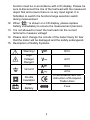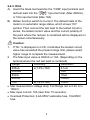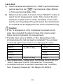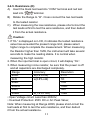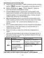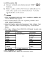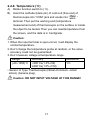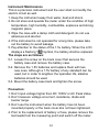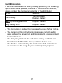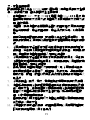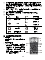
1
MT-1232
3-3/4 Autorange Digital Multimeter
User’s Manual
st
,
1 Edition 2013
©2013 Copyright by Prokit’s Industries Co., Ltd.
Contents
General------------------------------------------------------------------1
Open-Package Inspection------------------------------------------2
Safety Note -------------------------------------------------------------2
Instrument Panel& Button Function Description---------------5
Other Functions--------------------------------------------------------6
Properties----------------------------------------------------------------6
Instrument Maintenance--------------------------------------------16
Fault Elimination------------------------------------------------------17
General
This product equipped with the LCD display of text height 15mm,
is a 3 3/4 digital multimeter which has the merits of clear reading,
stable performance and high reliability. It could be used to
measure DC voltage, AC voltage, DC current, AC current,
resistance, capacity, frequency/duty cycle, diode and make
on-and-off test. Meanwhile, it is available for unit symbol display,
automatic/manual range switching, automatic power off and
alarm function. The multimeter, due to its complete functions,
performs with high measurement accuracy and convenient
operation, and is ideal for general electrical testing and
troubleshooting
1
Open-package Inspection
Open the package box and take out the meter, check carefully
if the following accessories are missing or damaged. If there
is anything missing or damaged, please contact the distributor
immediately.
Digital multimeter
1 PC
User’s manual
1 copy
Test leads
1 pair
Temperature Probe (K-Thermocouple)
1 PC
Test Socket
1PC
Safety Note
The design of this meter is in accordance with IEC1010 clause
(the safety standard issued by International Electrotechnical
Commission). Prior to the operation of the instrument, please
read the safety considerations before use.
1. When DC voltage is above 30V, AC voltage above 25V,
current above 10mA, AC power line with inductive load or
power line during electric fluctuation is measured, please
beware of electric shock.
2. Prior to measurement, check if the measurement function
switch is at the correct position. Check if the test lead is
contacted reliably, connected correctly, and grounded well
etc. in order to avoid electric shock.
3. Only if the meter is used with the matched test lead, does it
meet the requirement of the safety standard. When the line
of the test lead is damaged, it is necessary to replace with
another one of the same model or the same electrical
specification.
4. Don’t use other unconfirmed or disapproved fuses to replace
the fuse inside the meter. Only the same model or same
2
specification fuse can be replaced. Before the replacement,
the test leads must be removed from the measuring point
and ensure there is no any signal at the input terminal.
5. Don’t use other unconfirmed or disapproved battery to
replace the battery inside the meter. Only the same model or
same electrical specification battery can be replaced. Before
the replacement, the test lead must be removed from the
measuring point and ensure there is no any signal at the
input terminal.
6. When the electrical measurement is made, never let your
body gets in touch with the ground directly, and don’t touch
uncovered metal terminal, output port, lead clamp and etc.
where earth potential may exist. Dry clothes, rubber shoes,
rubber cushion and other insulating material are usually
used to keep your body insulated against the ground.
7. Don’t store and use it in the high-temperature, high-humidity,
inflammable and strong magnetic field environment.
8. It may damage to the meter and endanger the operator’s
safety if the voltage value beyond the permitted ultimate
voltage value is measured. The ultimate voltage value
permitted for measurement is marked on the instrument
panel, and never measure the value exceeding the standard.
Don’t input the ultimate value out of regulation in order to
avoid electric shock and the damage to the meter.
9. When the test lead is inserted into the current socket, don’t
measure any voltage for fear that the meter should be
damaged and the operator’s safety be endangered.
10. Don’t try calibrating or repairing the meter. When necessary,
only the qualified professional personnel who have had
special training or gained approval can make it.
11. During measurement, the requirement of measurement
3
12.
13.
14.
15.
function must be in accordance with LCD display. Please be
sure to disconnect the line of the test lead with the measured
object first and ensure there is no any input signal. It is
forbidden to switch the function/range selection switch
during measurement
When “
” is shown on LCD display, please replace
battery immediately to ensure the measurement precision.
It is not allowed to insert the test lead into the current
terminal to measure voltage!
Please don’t change the circuits of the meter freely for fear
that the meter will be damaged and the safety endangered.
Description of Safety Symbols
Warning!
DCV
High
Voltage!
Danger!
ACV
DCA
Ground
ACA
Double
Insulation
In accordance with the
instruction of European
Trade Union
Low
Battery
Fuse
4
Instrument Panel & Function Button Description
1. Instrument model number
2. LCD Display: Displays the measured data and unit.
3. Function Button
3.1 Hz/% (Frequency/Duty Cycle)
Press this button to select the
frequency or duty cycle mode.
The measurement mode of
voltage/frequency/duty cycle or
current/frequency/duty cycle
could be selected by pressing
this button in AC/DC voltage or
AC/DC current .
3.2 REL (Relative Value
Measurement): The relative value measurement of
Capacitance function could be conducted by pressing this
button
3.3 D/¤ :( Data hold/ Backlight): Press the left side of this
button, the reading is locked; press it again (the left side),
the lock will release and back to normal measurement
status. Press the right side of this button over 3 seconds,
the backlight will come on, press this button(the right side)
again the backlight turns off.
3.4 S: (Function Switch): Press this button, the function could
switch between DC/AC and
4. Knob Switch: Used to change the measurement function and
range.
5. Input Terminals
5.1. Current, Voltage, Diode, Resistance, Capacitance,
Frequency, Buzzer, Temperature “-” Input terminal.
5
5.2.10A“+”input terminal.
5.3. Voltage, Diode, Resistance, Capacitance, Frequency,
Buzzer, Temperature and“+” Input terminal with current
less than 400mA.
Other Functions
Auto Power off
During measurement, the meter will automatically shut down
(enter sleeping mode) to save power if function buttons and
knob switch are not operated for 15 minutes. In auto power off
mode, press any function buttons or rotate the knob switch,
the instrument will get into the auto power on mode (working
mode)
Properties
General Feature
1-1 Display: LCD
1-2 Max Display: 3999(3 3/4) counts automatic polarity display
and unit display
1-3 Measuring Method: Dual integral A/D converter
1-4 Sampling Range: Approx. 3 times / sec.
1-5 Over Range Indication: Display “OL”
1-6 Low Battery Indication: “
” symbol appears;
1-7 Operation Environment: (0~40)˚C Relative Humidity:<80%
1-8 Storage Environment: (0~50)˚C Relative Humidity:<80%
1-9 Power: 2 pcs 1.5V batteries (“AA” battery)
1-10 Dimension (size): 147×78×41mm
1-11 Weight: Approx. 183g
1-12 Accessories: User’s Manual (1 pc), color box (1 pc), 10A
test leads (1 pair), K-Thermocouple, Test Socket(1 pc)
6
Technical Features
2-1. Accuracy: ± (a%× reading +digits),at (23±5)˚C, relative
humidity<75%. One year calibration guarantee from the
time dispatched from the factory.
2-2. Technical Specification
2-2-1. DCV
A) Turn the knob switch to “
“Range
B) The default state of the meter is automatic range status,
which shows “AUTO” symbol
C) Put the test lead in contact with the testing point. The voltage
and polarity of the point where the red pen is contacted will be
displayed on the screen.
Caution:
1. Don’t measure voltage over 600V. Otherwise, there is a danger
of the meter being damaged.
2. When measuring high voltage, special attention should be
given to personal safety and avoid your body getting in touch
with high voltage circuit.
Range
Accuracy
Resolution
±(0.5%+4d)
400mV
100uV
4V
1mV
40V
10mV
400V
100mV
600V
±(1.0%+4d)
1V
• Input Impedance: 400m >40MΩ; 10MΩ at other Ranges.
• Overload Protection: 600V DC or 600V AC Peak Value.
7
2-2-2. ACV
A) Insert black test lead into the hole of “COM” and red test
“
lead into “
“, press “SELECT” button to
Rotate function switch to “
select the AC measurement mode.
C) The default state of the meter is in automatic range status,
which shows “AUTO” symbol
D) Put the test lead in contact with the testing point. The voltage
of the point where the red test lead is contacted will be
displayed on the screen.
B)
Caution:
Don’t measure voltage over 600V. ; Otherwise, the meter will
be damaged.
2. When measuring high voltage, special attention should be
given to personal safety and avoid your body getting in touch
with high voltage circuit.
Range
Accuracy
Resolution
±(0.8%+6d)
4V
1mV
40V
10mV
400V
100mV
600V
±(1.0%+6d)
1V
• Input Impedance: >10MΩ
• Overload Protection: 600V DC or 600V AC Peak Value
• Frequency Response: (50~200) Hz
• Display: Average value response (RMS of sine wave).
1.
8
2-2-3. DCA
A) Insert the black test lead into the “COM” input terminal and
red test lead into the “
“input terminal. (Max 400mA),
or 10A input terminal (Max 10A).
B) Rotate function switch to Current. The default state of the
meter is in automatic range status, which shows “DC”
symbol. Then connect the test lead to the tested circuit in
series, the tested current value and the current polarity of
the point where the red pen is contacted will be displayed on
the screen simultaneously.
Caution:
If “OL” is displayed on LCD, it indicates the tested current
value has exceeded the present range limit, please select
higher range to complete the measurement.
2. The Max input value is 400mA or 10A. (Depending on the
terminal where the red test lead is contacted)
Range
Accuracy
Resolution
±(1.0%+10d)
400uA
0.1uA
4000uA
1uA
40mA
10uA
400mA
100uA
10A
±(1.2%+10d)
10mA
• Max measurement voltage drop: Full Range mA is 0.4V, A is
100mV;
• Max input current: 10A (less than 15 seconds);
• Overload Protection: 0.4A/250V restorable fuse, 10A/250V
fuse.
1.
9
2-2-4. ACA
A) Insert the black test lead into the “COM” input terminal and
red test lead into the “
“input terminal. (Max 400mA),
or 10A input terminal (Max 10A).
B) Rotate function switch to Current. Press “SELECT” button to
select the AC measurement mode. Then connect the test
lead to the tested circuit in series, the tested current value
and the current polarity of the point where the red test lead
is contacted will be displayed on the screen simultaneously.
Caution:
1. If “OL” is displayed on LCD, it indicates the tested current
value has exceeded the present range limit, please select
higher range to complete the measurement.
2. The Max input value is 400mA or 10A. (Depending on the
terminal where the red test lead is contacted) The overrated
current will lead to fuse melt or even damage the meter.
Range
Accuracy
Resolution
±(1.5%+10d)
400uA
0.1uA
4000uA
1uA
40mA
10uA
400mA
100uA
10A
±(2.5%+15d)
10mA
• Max measurement voltage drop: Full Range mA is 0.4V, A is
100mV; Max input current: 10A (less than 15 seconds);
• Overload Protection: 0.4A/250V restorable fuse, 10A/250V
fuse; Frequency Response: 10A Range (50~200)Hz.
10
2-2-5. Resistance (Ω)
A) Insert the black test lead into “COM” terminal and red test
lead into “
“terminal.
B) Rotate the Range to “Ω”. Cross connect the two test leads
to the tested resistor.
C) When measuring the low resistance, please short-circuit the
test leads at first to test the wire resistance, and then deduct
it from the actual resistance.
Caution:
1. If “OL” is displayed on LCD, it indicates the tested resistance
value has exceeded the present range limit, please select
higher range to complete the measurement. When measuring
the Resistor higher than 1MΩ, the instrument will take several
seconds to make the reading stable. It is normal when
measuring the high resistor.
2. When the input terminal is open circuit, it will display “OL”.
3. When measuring in-line resistor, be sure that the power is off
and all capacitors are discharged completely.
Range
Accuracy
Resolution
400Ω
±(0.8%+5d)
0.1Ω
±(0.8%+4d)
4kΩ
1Ω
40kΩ
10Ω
400kΩ
100Ω
1kΩ
4MΩ
40MΩ
±(1.2%+10d)
10kΩ
• Open Voltage circuit: Less than 200mV;
• Overload Protection: 250V DC or AC Peak Value;
Note: When measuring at Range 400Ω, please short-circuit the
test leads at first to test the wire resistance, and then deduct
it from the actual resistance.
11
2-2-6.Diode and Continuity Test
A) Insert the black test lead to “COM” terminal and the red test
lead to “
” terminal. (The polarity of red test lead is“+”).
B) Rotate the Range to “
“. Press “SELECT” button to
select the Diode measurement mode.
C) Forward Measurement: Connect the red test lead to the
diode positive polarity and the black test lead to the diode
negative polarity. The approximate value of diode forward
voltage drop will show on the display.
4. Backward Measurement: Connect the red test lead to the
diode negative polarity and the black test lead to the diode
positive polarity. “OL” symbol will be displayed on the
screen.
5. The complete diode testing includes forward and backward
measurement, if the result does not meet the above; it
means the diode is bad.
6. Press “S” button to select the Continuity measurement
mode.
7. Connect the test leads to two points of the tested circuit. If
the built-in buzzer sounds, the resistance between the two
points is less than 50Ω.
Display
Test Condition
Range
Forward Voltage
Forward DC Current is
Drop of Diode
Approx. 0.5mA, Backward
Voltage is Approx. 1.5V
Buzzer makes
Open circuit voltage is
a long sound if
Approx. 0.5V
resistance is less
than 50Ω
• Overload Protection: 250V DC or AC Peak Value.
CAUTION: DO NOT INPUT VOLTAGE AT THIS RANGE!
12
2-2-7. Capacitance (F)
A) Rotate function switch to “
“.
B) Insert the black test lead to “COM” terminal and red test
lead to “
“ terminal or insert the test socket.
C) Connect the tested capacity by the test leads to “COM”,
“
“ input terminal or insert the test socket hole Cx - / +,
the screen will show capacitance parameter. (The relative
value measurement could be conducted by pressing “REL”
button.)
Caution:
1. Fully discharge the tested capacitor in case it damages the
meter.
2. When measuring in-line capacitor, the power should be turned
off and all capacitors should be discharged completely.
3. It takes about 30 seconds to input stable reading at 100uF
Range.
Range
Accuracy
Resolution
4nF
±(5.0%+9d)
1 pF
±(3.5%+8d)
40nF
10pF
400nF
100pF
4μF
1nF
40μF
10nF
100μF
±(5.0%+8d)
100nF
• Overload Protection: 250V DC or AC Peak Value.
13
2-2-8. Frequency (Hz)
A) Connect test leads and shielded cable to “COM”, “
”
terminals.
B) Rotate function switch to “Hz”. Connect test leads and the
cable to the signal source or the tested load. The tested
signal will show on the screen.
Caution:
1. When inputting AC RMS over 10V, it could show reading, but
excess vibration may appear.
2. It is recommended to test weak signals by shielded cable
under noisy circumstances.
3. Select ACV when testing the frequency of high voltage. Then
press “Hz/DUTY” button to enter frequency measurement
status.
4. Don’t input voltage of over 250V DC or AC peak value in case
it damages the meter.
Range
Accuracy
Resolution
±(0.5%+10d)
1Hz
0.001Hz
10Hz
0.01Hz
100Hz
0.1Hz
1kHz
1Hz
10kHz
10Hz
100kHz
100Hz
1MHz
1kHz
10MHz
10kHz
0.1-99.9%
For your reference
0.1V
• Input Sensitivity: >0.7V RMS
• Overload Protection: 250V DC or AC Peak Value.
14
2-2-9. Temperature (˚C)
A)
Rotate function switch to (˚C).
B) Insert the cathode (black pin) of cold end (free end) of
thermocouple into “COM” jack and anode into “
”
terminal. Then put the working end (temperature
measurement end) of thermocouple on the surface or inside
the object to be tested. Then you can read temperature from
the screen, and the data is in Centigrade.
Caution:
1. When the input terminal is open-circuit, it will display the
normal temperature.
2. Don’t change the temperature probe at random, or the value
accuracy could not be guaranteed.
3. Don’t measure voltage at temperature range.
Range
Accuracy
Resolution
(-20~1000)˚C <400˚C±(1.0%+5d)
1˚C
≥400˚C±(1.5%+15d)
• Sensor: K Type Thermocouple (Nickel-chromium--nickel
silicon) (banana plug).
Caution: DO NOT INPUT VOLTAGE AT THIS RANGE!
15
Instrument Maintenance
This is a precision instrument and the user shall not modify the
electric circuit as well.
1. Keep the instrument away from water, dust and shock.
2. Do not store and operate the meter under the condition of high
temperature, high humidity, combustible, explosive and strong
magnetic place.
3. Wipe the case with a damp cloth and detergent; do not use
abrasives and alcohol.
4. If the instrument is not operated for a long time, please take
out the battery to avoid leakage.
5. Pay attention to the status of the 1.5v battery. When the LCD
displays a flashing “
”symbol, the battery shall be replaced.
The steps are as follows:
5-1. Loosen the screw on the back cover that secures the
battery case and remove the battery case.
5-2. Remove the 1.5V batteries and replace them with two
new ones. Although a 1.5V battery of any standard can be
used, but in order to lengthen the operation life, alkaline
batteries should be used.
5-3. Mount the battery case back and tighten the screw.
Precaution:
1. Don’t input voltage higher than DC 1000V or AC Peak Value.
2. Don’t measure voltage at current, resistance, diode and
buzzer range.
3. Don’t use the instrument when the battery has not been
mounted properly or the back cover ahs not been tightened.
4. Prior to the replacement of battery or fuse, please remove the
test leads from the measuring point and switch off the meter.
16
Fault Elimination
If the instrument does not work properly, please try the following
tips to solve some general problems. If the problems still exist,
please contact the maintenance center or the distributor.
Fault
Solution
Turn on power.
No Display
Replace battery
symbol appearance
Big display error
Replace battery.
Replace battery
• This Instruction is subject to change without any further notice.
• The content of this Instruction is considered correct, and in
case readers find any errors and missing parts, please contact
the manufacturer.
• The Company shall not be held liable for any accidents and
hazards resulted from the mal-operations by the user.
• The function elaborated by this Instruction shall not be taken
as the reasons for using the product for special purposes.
17
目 錄
一.概述-------------------------------------------------------------------------18
二.開箱檢查-------------------------------------------------------------------18
三.安全注意事項-------------------------------------------------------------19
四.儀錶面板及按鍵功能說明---------------------------------------------20
五.其他功能------------------------------------------------------------------- 21
六.特性------------------------------------------------------------------------- 21
七.儀錶保養------------------------------------------------------------------- 29
八.故障排除------------------------------------------------------------------- 30
一、概述
MT-1232 是一款性能穩定、高可靠性 3 3/4 位元數字多用錶。儀
錶採用 15mm 字高 LCD 顯示器,讀數清晰。
可用來測量直流電壓、交流電壓、直流電流、交流電流、電阻、
溫度、電容、頻率/占空比、二極體及通斷測試。同時還設計有
單位符號顯示、自動/手動量程轉換、自動斷電及報警功能。該錶
功能齊全,測量準確度高,使用方便,是實驗室、工廠、無線電
愛好者及家庭的理想工具。
二、開箱檢查
打開包裝箱取出儀錶,仔細檢查以下附件是否缺少或損壞,
如有缺少或損壞請立即與經銷商聯繫。
● 數字多用錶
一台
● 使用說明書
一本
● 錶棒
一付
● 溫度探頭(K 型熱電偶)
一條
● 電晶體測試座
一個
18
三、安全注意事項
該儀錶在設計上符合 IEC1010 條款(國際電工委員會頒佈的安全標
準),在使用之前,請先閱讀安全注意事項。
1. 在測量直流 36V、交流 25V 以上電壓,測量 10mA 以上電流,測
量帶電感負載的交流電力線;測量電力波動期間的交流電力線
時, 謹防電擊。
2. 測量前,檢查測量功能開關是否置於正確的檔位,要檢查錶筆
是否可靠接觸,是否正確連接、是否絕緣良好等,以避免電
擊。
3. 儀錶只有和所配備的錶棒一起使用才符合安全標準要求。如
錶棒線破損時,必須更換上同樣型號或者相同電氣規格的錶棒
線
4. 不要使用其他未經確認或未認可的保險管來更換儀錶內部的
保險管。只能換上同樣型號或相同規格的保險管。更換前,錶
棒必須離開被測量點,確保輸入端無任何信號。
5. 不要使用其他未經確認的電池來更換儀錶內的電池。只能換
上同型號或相同電氣規格的電池。更換前,錶棒必須離開被測
量點,確保輸入端無任何信號。
6. 在進行電氣測量時,身體切勿直接接觸大地,不要接觸可能存
在地電勢裸露的金屬端子、輸出口、引線夾等。通常使用乾
燥的衣服、膠鞋、膠墊以及其他絕緣材料,保持你的身體與大
地絕緣。
7. 不要在高溫、高濕、易燃、易爆和強磁場環境中存放及使用。
8. 測量超過儀錶所允許的極限電壓值有可能損壞儀錶和危及操
作人員的安全。在儀錶面板上標有儀錶所允許測量的極限電
壓值切勿測量超過此標準的安全,請勿輸入超過規定的極限
值,以防電擊和損壞儀錶。
9. 當錶棒線插入電流插座時切勿測量任何電壓以免損壞儀錶和
危及操作人員的安全。
10. 不要嘗試校準或維修儀錶。的確有需要時必須有專門培訓或
認可的有資格專業人員才能進行。
19
11. 在測量時功能/量程選擇開關必需置於正確的量程檔位,在轉
換功能/量程選擇開關時,請一定要先將錶棒線與被測物件斷
開,確保輸入端沒任何信號輸入。嚴禁在測量進行中轉換功能/
量程選擇開關。
12. 當 LCD 顯示“
"時,請及時更換電池以確保測量精度。
13. 不允許在電流檔去測量電壓!
14. 請不要隨意改變儀錶線路,以免損壞儀錶和危及安全。
15. 安全符號說明:
警告!
直流電壓
高壓!危險!
交流電壓
直流電流
大地
交流電流
符合歐洲工
雙重絕緣
會指令
低電壓指示
保險絲
四、儀錶面板及按鍵功能說明
1. 儀錶型號
2. 液晶顯示器:顯示儀錶測量的數值
及單位
3. 功能按鍵說明
3.1. Hz/% : (頻率/占空比):在頻率檔
觸發此鍵, 可選擇頻率或占空比
測量模式. 交/直流電壓或交直
流電流檔位, 觸發此鍵, 可進行
電壓/頻率/占空比或電流/頻
率/占空比測量模式
20
3.2. REL: (相對值測量):在電
容檔觸發此鍵, 可進行相對值測量模式.
3.3. D/¤ : (數據保持/背光功能):觸發此鍵左側時, 鎖定數值功能,
顯示值被鎖定, 一直保持不變. 再按此鍵(左側)時, 鎖定狀
態被解除, 進入正常狀態。 觸發此鍵右側大於 3 秒, 背光功
能實現. 再觸發此鍵(按右側)關閉背光.
3.4 S: (功能切換): 觸發此鍵時,功能會在 DC/AC
之間切換
4. 旋鈕開關:用於改變測量功能及量程。
5. 輸入插孔
5.1. 電流、電壓、二極體、電阻、電容、頻率、蜂鳴器、溫度的
“-"輸入插孔
5.2. 10A“+"輸入插孔
5.3. 電壓、二極體、電阻、電容、頻率、蜂鳴器、溫度“+"及
小於 400mA 電流的輸入插孔
五、其他功能
自動關機
在測量過程中,功能按鍵和撥盤開關在 15 分鐘內均無動作時,
儀錶會“自動關機"(休眠狀態),以節約電能;在自動關
機狀態下,按動功能鍵或是轉動撥盤開關,儀錶會“自動開
機"(工作模式)
六、特性
1.一般特性
1-1. 顯示方式:液晶顯示
1-2. 最大顯示:3999(3 3/4 位元)自動極性和單位顯示
1-3. 測量方式:雙積分式 A/D 轉換
1-4. 轉換速率:約每秒 3 次
1-5. 過量程顯示:顯示“OL"
1-6. 低電壓顯示:“
"符號出現;
1-7. 工作環境:(0~40)℃,相對濕度<80% ;
21
1-8. 相對溫度:(0~50)℃,相對濕度<80% ;
1-9. 電源:兩節 1.5V 電池(“AA"電池)
;
1-10. 體積(尺寸):147×78×41mm (長×寬×高)
1-11. 重量:約 183g
1-12. 附件:使用說明書一本、外包裝盒各一個,10A 錶棒一付、
K 型熱電偶線一條、電晶體測試座一個。
2.技術特性
2-1. 準確度:±(a%×讀數+字數),保證準確度環境溫度:(23±5)°C,相
對濕度<75%,校準保證期從出廠日起為一年。
2-2. 性能
功能
有/無
直流電壓 DCV
有
交流電壓 ACV
有
直流電流 DCA
有
交流電流 ACA
有
電阻 Ω
有
電容 CAP
有
頻率 Hz
有
二極體/通斷
有
溫度 °C
有
2-3-1.直流電壓(DCV)
A). 將功能開關轉至“
"檔
B). 儀錶初始為自動量程狀態,顯示“AUTO"符號
C.) 將測試錶棒接觸測試點,紅錶棒所接的該點電壓與極性顯示在
螢幕上。
注意:
1. 測量電壓切勿超過 600V,超過則有損壞儀錶電路的危險。
2. 當測量高電壓電路時,千萬注意避免人體觸及高壓電路,注意
人身安全。
22
量程
400mV
4V
40V
400V
600V
準確度
±(0.5%+4d)
±(1.0%+4d)
分辨力
100uV
1mV
10mV
100mV
1V
‧輸入阻抗:400mV 大於 40MΩ;其餘為 10MΩ。
‧超載保護:600V 直流或 600V 交流峰值;
2-3-2.交流電壓(ACV)
1.將黑錶棒插入“COM"插孔,紅錶棒插入“
"插孔;
2.將功能開關轉至“
"檔,按動“SELECT"鍵選擇 AC 測量方
式
3.儀錶初始為自動量程狀態,顯示“AUTO"符號;
4.將測試錶棒接觸測試點,紅錶棒接的該點電壓顯示在螢幕上。
注意:
1. 測量電壓切勿超過 600V,如超過,有損壞儀錶電路的危險。
2. 當測量高電壓電路時,千萬注意避免人體觸及高壓電路,注意
人身安全。
量程
準確度
分辨力
±(0.8%+6d)
4V
1mV
40V
10mV
400V
100mV
600V
±(1.0%+6d)
1V
‧輸入阻抗: 大於 10MΩ。
‧超載保護:600V 直流或 600V 交流峰值;
‧頻率回應:(50~200)Hz
‧顯 示:平均值響應(以正弦波有效值校準)。
23
2-3-3.直流電流(DCA)
A)
將黑錶棒插入“COM"插孔,紅錶棒插入“
"插孔(最
大為 400mA),或插入“10A"插孔中(最大為 10A)
B)
將功能開關轉至電流檔,儀錶初始為自動量程狀態,顯示
“DC"符號,然後將儀錶的錶棒串入被測電路中,被測電流
值及紅色錶棒點的電流極性將同時顯示在螢幕上。
注意:
如 LCD 顯示“OL",表明已超過量程範圍,需將量程開關轉
至較高一檔。
2. 最大輸入電流為 400mA 或者 10A(視紅錶棒插入位置而定),
超過額定的電流會將保險絲熔斷,甚至損壞儀錶。
量程
準確度
分辨力
±(1.0%+10d)
400uA
0.1uA
4000uA
1uA
40mA
10uA
400mA
100uA
10A
±(1.2%+10d)
10mA
‧最大測量壓降:滿量程 mA 為 0.4V,A 為 100mV;
‧最大輸入電流:10A(不超過 15 秒);
‧超載保護:0.4A/250V 自恢復保險絲,10A/250V 保險管。
1.
2-3-4.交流電流(ACA)
1. 將黑錶棒插入“COM"插孔,紅錶棒插入“
"插孔(最
大為 400mA),或插入“10A"插孔中(最大為 10A);
2. 將功能開關轉至電流檔,按動“SELECT"鍵選擇 AC 測量方
式,然後將儀錶的錶棒串入被測電路中,被測電流值及紅色
錶棒點的電流極性將同時顯示在螢幕上。
24
注意:
如 LCD 顯示“OL",表明已超過量程範圍,需將量程開關轉
至較高一檔。
2. 最大輸入電流為 400mA 或者 10A(視紅錶棒插入位置而定),
超過額定的電流會將保險絲熔斷,甚至損壞儀錶。
量程
準確度
分辨力
±(1.5%+10d)
400uA
0.1uA
4000uA
1uA
40mA
10uA
400mA
100uA
10A
±(2.5%+15d)
10mA
‧最大測量壓降:滿量程 mA 為 0.4V,A 為 100mV;
‧最大輸入電流:10A(不超過 15 秒)。
‧超載保護:0.4A/250V 自恢復保險絲,10A/250V 保險管。
‧頻率回應:10A 量程為(50~200)Hz。
1.
2-3-5.電阻(Ω)
1.
將黑錶棒插入“COM"插孔,紅錶棒插入“
A)
將量程開關轉至“Ω"檔,兩錶棒跨接在被測電阻上。
B)
如果測量阻值小的電阻,應先將錶棒短路,測得引線電阻,
"插孔;
然後在實測中減去。
注意:
如 LCD 顯示“OL",表明已超過量程範圍,需將量程開關轉
至較高一檔,當測量電阻超過 1MΩ 以上時,讀數幾秒之後才
能穩定,這在測量高阻時是正常的。
2. 當輸入端開路時,則顯示“OL"。
3. 測量線上電阻時,要確認被測電路所有電源已關閉及所有電
容都已完全放電,才可進行。
1.
25
量程
準確度
分辨力
400Ω
±(0.8%+5d)
0.1Ω
±(0.8%+4d)
4kΩ
1Ω
40kΩ
10Ω
400kΩ
100Ω
1kΩ
4MΩ
40MΩ
±(1.2%+10d)
10kΩ
‧開路電壓:小於 200mV;
‧超載保護:250V 直流或交流峰值;
‧注意事項:在使用 400Ω 量程時,應先將錶棒短路,測得引線電
阻,然後在實測中減去
2-3-6.二極體及通斷測試
A)
將黑錶棒插入“COM"插孔,紅錶棒入“
"插孔(注
意紅錶棒極性為“+"極)
;
B)
C)
D)
E)
F)
G)
將量程開關轉至“
"檔,按動“SELECT"鍵選擇二極
體測量方式;
正向測量:將紅錶棒接到被測二極體的正極,黑錶棒接到被
測二極體的負極,顯示器即顯示二極體正向壓降的近似值;
反向測量:將紅錶棒接到被測二極體的負極,黑錶棒接到被
測二極體的正極,顯示器顯示“OL"字樣;
完整的二極體測試包括正反向測量,如果測試結果與上述不
符,說明二極體是壞的。
按動“S"鍵選擇通斷測量方式,
將錶棒連接到待測線路的兩點,如果內置蜂鳴器發聲,則兩
點之間電阻值低於約 50Ω,則內置蜂鳴器發聲。
26
量程
顯示值
二極體正向壓降
蜂鳴器發聲長響,測
試兩點阻值約 50Ω
‧超載保護:250V 直流或交流峰值;
測試條件
正向直流電流 0.5mA
反向
電壓約 1.5V
開路電壓約 0.5V
警告:為了安全在此量程禁止輸入電壓值!
2-3-7.電容(F)
1. 將功能開關轉至“
"檔;
2. 將黑錶棒插入“COM"插孔,紅錶棒插入“
或將錶棒換為測試座插入。
3.
" 插孔,
用測試錶棒(注意紅錶棒極性為正極)將被測電容接入
“COM〞〞
"輸入端或插入測試座 Cx-/+孔中,螢幕將顯
示電容容量。(按動“REL"鍵可進行相對值測量)
注意:
1. 對被測電容應完全放電,以防止損壞儀錶;
2. 測量線上電容時,需將線路電源關斷,並將電容充分放電;
3. 100uF 量程輸入讀數穩定時間約 30 秒。
量程
準確度
分辨力
4nF
±(5.0%+9d)
1 pF
±(3.5%+8d)
40nF
10pF
400nF
100pF
4μF
1nF
40μF
10nF
100μF
±(5.0%+8d)
100nF
‧ 超載保護:250V 直流或交流峰值。
27
2-3-8.頻率(Hz)
1. 將錶棒或遮罩電纜接入“COM"、“
"輸入端;
2. 將功能開關轉至“Hz"檔,將錶棒或電纜跨接在信號源或被測
負載上,被測信號的頻率顯示在螢幕上。
注意:
輸入超過 10V 交流有效值時,可以讀數,但可能超差;
在雜訊環境下,測量小信號時最好使用屏壁電纜;
測量高電壓的頻率時,請選擇 ACV 檔,再按 Hz/DUTY 按鍵
進入頻率測量狀態
4. 禁止輸入超過 250V 直流或交流峰值的電壓,以免損壞儀錶。
程量
準確度
分辨力
1Hz
±(0.5%+10d)
0.001Hz
10Hz
0.01Hz
100Hz
0.1Hz
1kHz
1Hz
10kHz
10Hz
100kHz
100Hz
1MHz
1kHz
10MHz
10kHz
0.1-99.9%
僅供參考
0.1V
‧ 輸入靈敏度:>0.7V 有效值
‧ 超載保護:250V 直流或交流峰值。
1.
2.
3.
2-3-9.溫度(°C)
1. 將功能開關轉至“℃"檔.
2. 將熱電偶感測器的冷端(自由端)負極(黑色插頭)插入
“COM"插孔,正極插入“
"插孔中,熱電偶的工作
端(測溫端)置於待測物上面或內部,可直接從螢幕上讀取
溫度值,讀數為攝氏度。
28
注意:
1. 當輸入端開路時,則顯示常溫。
2. 請勿隨意更換測溫感測器,否則將不能保證測量準確度。
3. 嚴禁在溫度檔測量電壓。
量程
準確度
分辨力
(-20~1000)˚C
<400˚C±(1.0%+5d)
1˚C
≥400˚C±(1.5%+15d)
感測器:K 型熱電偶(鎳鉻—鎳矽)香蕉插頭。
警 告:為了安全在此量程禁止輸入電壓值!
七、儀錶保養
該儀錶是一台精密儀器,使用者不要隨意更改電路。
1. 請注意防水、防塵、防摔
2. 不宜在高溫高濕、易燃易爆和強磁場的環境下存放、使用儀
錶
3. 請使用濕布和溫和的清潔劑清潔儀錶外表,不要使用研磨劑
及酒精等烈性溶劑
4. 如果長時間不使用,應取出電池,防止電池漏液腐蝕儀錶
5. 注意 1.5V 電池使用情況,當螢幕顯示出“
"符號時,應
更換電池,步驟如下:
5-1. 卸下固定電池盒的螺絲,取出電池盒
5-2. 取出 1.5V 電池,換上兩個新的電池,雖然任何標準 1.5V
電池都可使用,但為加長使用時間,最好使用鹼性電池
5-3. 裝回電池盒,鎖緊螺絲。
29
注意:
不要將 1000V 直流或交流峰值電壓接入
不要在電流檔、電阻檔、二極體檔和蜂鳴器檔上,測量電壓
值
3. 在電池沒有裝好或後蓋沒有上緊時,請不要使用此錶
4. 在更換電池或保險絲前,請將測試錶棒測試點移開,並關機。
1.
2.
八、故障排除
如果您的儀錶不能正常工作,下面的方法可以幫助您快速解決一
般問題。如果故障仍排除不了,請與維修中心或經銷商聯繫。
故障現象
檢 查 部 位 及 方 法
沒顯示
電源未接通 / 換電池
符號出現
換電池
顯示誤差大
換電池
• 本說明書如有改變,恕不另行通知
• 本說明書的內容被認為是正確的,若用戶發現有錯誤、遺漏
等,請與生產廠家聯繫
• 本公司不承擔由於用戶錯誤操作所引起的事故和危害
• 本說明書所講述的功能,不作為將產品用做特殊用途的理
由。
30
©2013 Prokit’s Industries Co., LTD. All rights reserved 2013001(T)
31