1
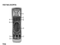
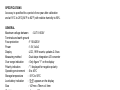
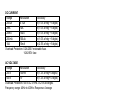
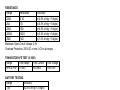
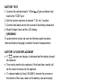
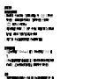
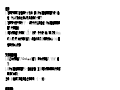
MT-1132 3-1/2 Digital Multimeter User’s Manual st , 1 Edition 2012 ©2012 Copyright by Prokit’s Industries Co., Ltd. SAFETY INFORMATION This multimeter has been designed according to IEC 1010 concerning electronic measuring instruments with an overvoltage category (CAT III) and pollution 2. Follow all safety and operating instructions to ensure that the meter is used safely and kept in good operating condition. Full compliance with safety standards can be guaranteed only with test leads supplied. If necessary, they must be replaced with the type specified in this manual. SAFETY SYMBOLS Important safety information, refer to the operating manual. Dangerous voltage may be present. Earth ground Double insulation (Protection class II). Fuse must be replaced with rating specified in the manual. MAINTENANCE Before opening the case, always disconnect test leads from all energized circuits. For continue protection against fire; replace fuse only with the specified voltage and current ratings: F10A/250V (Quick Acting) Never use the meter unless the back cover is in place and fastened completely Do not use abrasives or solvents on the meter. To clean it using a damp cloth and mild detergent only. 1 DURING USE Never exceed the protection limit values indicated in specifications for each range of measurement. When the meter is linked to measurement circuit, do not touch unused terminals. Never use the meter to measure voltages that might exceed 500V above earth ground in category III installations. When the value scale to be measured is unknown, set the range selector at the highest position. Before rotating the function / range selector to change functions, disconnect test leads from the circuit under test. When carrying out measurements on TV or switching power circuits always remember that there may be high amplitude voltages pulses at test points, which can damage the meter. Always careful when working with voltages above 60V DC or 30V AC rms. Keep fingers behind the probe barriers while measuring. Before attempting to insert transistors for testing, always be sure that test leads have been disconnected from any measurement circuits. Components should not be connected to the hFE socket when making voltage measurements with test leads. Never perform resistance measurements on live circuits. GENERAL DESCRIPTION The meter is a handheld 3 1/2 digital multimeter for measuring DC and AC voltage, DC current, Resistance, Diode, Transistor and Continuity Test with battery operated. 2 FRONT PANEL DESCRIPTION Display 1. 3 1/2 digit, 7 segment, 15mm high LCD. 2. Backlight button 3. Function/range selector Rotate this selector to select function and desired range 4. Data hold button Press this button, the display will keep the last reading and " " symbol will appear on the LCD until pushing it again. 5. "10A" jack 6. “COM" jack 7. Voltage, resistance, current (except 10A) measurements, Continuity check and Diode test. 8. Power on/off button 9. LED test socket 3 SPECIFICATIONS Accuracy is specified for a period of one year after calibration and at 18°C to 28°C(64°F to 82°F) with relative humidity to 80%. GENERAL Maximum voltage between : CAT III 600V Terminals and earth ground Fuse protection : F 10A/250V Power : 1.5V, AAx2 Display : LCD, 1999 counts, updates 2-3/sec. Measuring method : Dual-slope integration A/D converter Over range indication : Only figure "1" on the display Polarity indication : "-" displayed for negative polarity Operating environment : 0 to 40ºC Storage temperature : -10ºC to 50ºC Low battery indication :" " appears on the display Size : 147mm x 78mm x 41mm Weight : Approx. 183g DC VOLTAGE Range Resolution Accuracy 200mV 100uV ±(0.5% of rdg + 2 digits) 2V 1mV ±(0.5% of rdg + 2 digits) 20V 10mV ±(0.5% of rdg + 2 digits) 200V 100mV ±(0.5% of rdg + 2 digits) 500V 1V ±(0.8% of rdg + 5 digits) Overload Protection: 250V rms. For 200mV range and 500V DC or rms. AC for other ranges. 4 DC CURRENT Range Resolution Accuracy 200uA 0.1uA ±(1.0% of rdg + 5 digits) 2mA 1uA ±(1.0% of rdg + 5 digits) 20mA 10uA ±(1.0% of rdg + 5 digits) 200mA 100uA ±(1.0% of rdg + 5 digits) 10A 10mA ±(2.5% of rdg + 5 digits) Overload Protection: 0.2A/250V restorable fuse. 10A/250V fuse AC VOLTAGE Range Resolution Accuracy 200V 100mV ±(1.2% of rdg+10digits) 500V 1V ±(1.2% of rdg+10 digits) Overload Protection: 500V DC or rms. AC for all ranges. Frequency range: 40Hz to 400Hz. Response: Average responding, calibrated in rms. of a sine wave. DIODE & CONTINUITY Range Description If continuity exists (about less than 50Ω), built-in buzzer will sound Show the approx. forward voltage drop of the diode Overload Protection: 250V DC or rms. AC. 5 RESISTANCE Range Resolution Accuracy 200Ω 0.1Ω ±(0.8% of rdg + 5 digits) 2kΩ 1Ω ±(0.8% of rdg + 5 digits) 20kΩ 10Ω ±(0.8% of rdg + 5 digits) 200kΩ 100Ω ±(0.8% of rdg + 5 digits) 2MΩ 1kΩ ±(1.0% of rdg + 5 digits) Maximum Open Circuit Voltage: 2.8V Overload Protection: 250V DC or rms. AC for all ranges. TRANSISTOR hFE TEST (0-1000) Range Test Range Test Current NPN & PNP 0-1000 Ib=10mA Test Voltage Vce=2.8V BATTERY TESTING Range Accuracy 1.5V ±(2.5% of rdg + 2 digits) OPERATING INSTRUCTIONS DC VOLTAGE MEASUREMENT 1. Connect the red test lead to the "VΩmA " jack and the black test lead to the "COM" jack. 2. Rotate the function selector to the desired DCV position. If the voltage to be measured is not known, set the selector to the highest range position, and then reduce the range until proper resolution is obtained. 3. Connect test leads across the source or load being measured. 4. Read voltage value on the LCD display along with the polarity of the red test lead connection. 6 DC CURRENT MEASUREMENT 1. Connect the red test lead to the "VΩmA " jack and the black test lead to "COM" jack. (For measurements between 200mA and 10A, remove red test lead to "10A" jack.) 2. Set the function selector to the desired DCA position. 3. Open the circuit in which the current is to be measured, and connect test leads in series with the circuit. 4. Read current value on LCD display along with the polarity of red test lead connection. AC VOLTAGE MEASUREMENT 1. Connect the red test lead to "VΩmA " jack and the black test lead to the "COM" jack. 2. Set the function selector to the desired ACV position. 3. Connect test leads across the source or load being measured. 4. Read voltage value on the LCD display. RESISTANCE MEASUREMENT 1. Connect the red test lead to "VΩmA " jack and black test lead to the "COM" jack. (The polarity of red test lead is positive "+".) 2. Set the function selector at desired "Ω" range position. 3. Connect test leads across the resistor to be measured and read LCD display. 4. If the resistance being measured is connected to a circuit, turn the power off and discharge all capacitors before applying test probes. 7 DIODE TEST 1. Connect the red test lead to "VΩmA " jack and the black test lead to the "COM" jack (The polarity of red lead is positive "+".). 2. Set the function selector at " " position. 3. Connect the red test lead to the anode of the diode to be tested and the black test lead to the cathode of the diode. The approx. forward voltage drop of the diode will be displayed. If the connection is reversed, only figure "1" will be shown. TRANSISTOR TEST 1. Set the function selector at "hFE" position. 2. Determine whether the transistor under testing is NPN or PNP and locate the emitter base and collector leads. Insert the leads into proper holes of the hFE socket on the front panel. 3. Read the approximate hFE value at the test condition of base current 10mA and Vce 2.8V. NOTE: To avoid electrical shock, remove test leads from measurement circuits before testing a transistor. AUDIBLE CONTINUITY TEST 1. Connect red test lead to "VΩmA " jack, black test lead to the “COM” jack 2. Set function selector to " " position. 3. Connect test leads to two points of circuit to be tested. If continuity exists, built-in buzzer will sound. 8 BATTERY TEST 1. Connect the red test lead to "VΩmA " jack and black test lead to the "COM" jack 2. Set the function selector at desired "1.5V mA " position 3. Connect test leads across the source of load being measured 4. Read Voltage Value on the LCD display WARNING To avoid electric shock, be sure the thermocouple has been removed before changing to another function measurement. BATTERY & FUSE REPLACEMENT If " " appears on display, it indicates that the battery should be replaced. Fuse rarely needs to be replaced, if the fuse blew, mostly will be the result of misuse by the operator To replace battery & fuse (10A/250V) remove the screws on the bottom of the case, take out the battery case and simply remove the old, and replace with a new one. Be careful to observe battery polarity. WARNING Before attempting to open the case, be always sure that test leads have been disconnected from measurement circuits. Close case and tighten screws completely before using the meter to avoid electrical shock hazard. ACCESSORIES • User’s manual • Set of test leads • Transistor test socket 9 MT-1132 3 1/2 數位電錶 使用說明書簡介 本儀錶是一款性能穩定、高可靠性和防跌落性能的小型掌上型3 1/2 位元數位多用錶。儀錶採用字高15mm的液晶顯示器,讀數清晰。 整機電路設計以大型積體電路雙積分A/D轉換器為核心,並配以超 載保護電路,使之成為一台性能優越小巧的工具儀錶。 此儀錶可用來測量直流和交流電壓、直流電流、電阻、二極體、 電晶體和電路通斷測試。 安全資訊 MT-1132 3 1/2數位電錶是根據IEC1010 CAT III 600V 和污染等級2 設計的。為保證儀錶能準確安全使用,請認真閱讀使用說明書。 安全標誌 重要的安全資訊,應參閱說明書 高壓危險 地 雙重絕緣(II類安全設備) 保險絲必須按說明書指定的規格更換 維護 在打開後蓋之前,測試錶棒應斷開測量電路。 為保護儀錶的內部線路,更換保險絲必須使用相同的規格,本儀 表使用的保險絲規格為:F10A/250V(快速)。 在後蓋未蓋妥,螺絲未鎖緊前,切勿使用儀錶。 清潔儀錶只能使用溼布和少量清潔劑,切忌用化學溶劑擦表殼。 如觀察到有任何異常,該儀錶應立即停止使用並送維修。 10 面板功能介紹 1. 3 1/2位、字高15mm 7段LCD顯示器 2. 背光鍵 3. 功能量程開關 用於選擇各功能和量程 4. 資料保持開關 在測量中按HOLD鍵,儀錶顯示器上將保持測量的最後讀數並且 LCD上顯示" "符號;釋放資料保持開關,儀錶即恢復正常測量 狀態 5. 10A插孔 6. COM插孔 7. VΩmA 插孔 8. 電源鍵 9. LED 測試座 11 使用注意事項 儀錶只能和所配備的測試錶棒一起使用才符合安全標準的要 求。如測試錶棒破損需要更換,必須換上同型號或相同電氣規 格的測試錶棒。 切勿超過每個量程所規定的輸入極限值。 當儀錶正在測量時,不要觸及沒有使用的輸入端。 在不能確定被測量的大小範圍時,將功能量程開關置於最大量 程位置。 在功能量程開關轉換之前,應使測試錶棒與被測電路處於開路 狀態。 進行線上電阻測量前,應切斷電路中所有電源並將所有電容器 放電。 測量高於 60V 直流 30V 交流以上的電壓時,務必小心,切記手 指不要超過測試錶棒擋手部份。 測量電視機或開關電源時,應注意電路中可能存在會損壞儀表 的脈衝。 在測試電晶體前,必須確保錶棒沒有連接到任何被測試電路。 用錶棒測量電壓前,必須確保電子元件連接在電晶體測試座上。 技術指標 準確度:±(%讀數+字數)。 環境溫度:18°C至28°C,環境溼度:80%。 一般特性: 電壓輸入端和地之間最大電壓 保險管 電源 最大顯示值 過量程指示 極性顯示 工作溫度 :CAT III 600V :F 10A/250V :1.5V 電池,AA x 2 :1999 :"1" :負極性顯示"-" :0 到 40°C 12 儲存溫度 低電壓指示 外型尺寸 重量 :10°C 到 50°C :顯示器顯示" " :147mm x 78mm x 41mm :約 183g 直流電壓測量 量程 分辨力 準確度 200mV 100uV ±(0.5%讀數 + 2 字) 2V 1mV ±(0.5%讀數 + 2 字) 20V 10mV ±(0.5%讀數 + 2 字) 200V 100mV ±(0.5%讀數 + 2 字) 500V 1V ±(0.8%讀數 + 5 字) 超載保護:200mV 量程 250V DC 或 rms;其餘量程 500V DC 或 rms 直流電流測量 量程 分辨力 準確度 200uA 0.1uA ±(1.0% 讀數 + 5 字) 2mA 1uA ±(1.0% 讀數 + 5 字) 20mA 10uA ±(1.0% 讀數 + 5 字) 200mA 100uA ±(1.0% 讀數 + 5 字) 10A 10mA ±(2.5 % 讀數 + 5 字) 超載保護: 0.2A / 250V 自恢復保險絲,10A/250V 保險絲)。 交流電壓測量 量程 分辨力 準確度 200V 100mV ±(1.2%讀數 + 10 字) 500V 1V ±(1.2%讀數 + 10 字) 超載保護: 500V DC 或 rms。 頻率範圍: 40Hz 到 400Hz 。 顯示:平均值(正弦波有效值)。 13 電阻 量程 分辨力 200Ω 0.1Ω 2kΩ 1Ω 20kΩ 10Ω 200kΩ 100Ω 2MΩ 1kΩ 最大開路電壓: 2.8V 超載保護: 250V DC 或rms 準確度 ±(0.8% 讀數 ±(0.8% 讀數 ±(0.8% 讀數 ±(0.8% 讀數 ±(1.0% 讀數 +5 +5 +5 +5 +5 字) 字) 字) 字) 字) 二極體和電路通斷測試 量程 說明 導通電阻小於約50Ω,機內蜂鳴器響。 顯示近似二極體正向電壓值。 超載保護: 250V DC 或rms. AC 電晶體hFE測試(0-1000) 量程 測試範圍 NPN & PNP 0-1000 電池測試 量程 1.5V 測試電流 Ib=10mA 準確度 ±(2.5%讀數 + 2 字) 14 測試電壓 Vce=2.8V 使用方法 操作前注意事項: 1. 接通電源,先檢查電池,如果電池電壓不足," " 將顯示在 顯示器上,這時則需要更換電池。如果顯示器上沒有顯示 " ",則按以下步驟操作。 2. 測試錶棒插孔旁邊的" " 符號,表示輸入電壓或電流不應超過 指示值,這是為了保護內部線路免受損傷。 3. 測試之前,功能量程開關應置於您所需要的量程。 直流電壓測量 1. 將紅色錶棒插入"VΩmA " 插孔,黑色錶棒插入"COM" 插 孔。 2. 將功能量程開關置於量程範圍,並將測試錶棒連接到待測試電源 或負載上,紅色錶棒所接端的極性將同時顯示於顯示器上。 注意 1. 如果被測量電壓範圍事先不知道,請將功能量程開關置於最大量 程,然後逐漸降低直至取得滿意的分辨力。 2. 如果顯示器只顯示 "1",這表示已經過量程,功能量程開關應置 於更高量程。 3. 不要輸入高於500V的電壓,顯示更高電壓是可能的,但有損壞儀 錶內部線路的危險。 4. 在測量高壓電時,要特別注意避免觸電。 直流電流測量 1. 將黑色錶棒插入COM插孔,當被測電流不超過200mA時,紅色色 錶棒插入"VΩmA "插孔。如果被測電流在 200mA和10A之 間,則將紅色錶棒插入10A插孔。 2. 將功能量程開關置於所需要的A量程位置,並將測試錶棒串連接 入到待測負載上,電流值顯示器紅色錶棒連接的極性。 15 注意 1. 如果被測電流範圍事先不知道,請將功能量程開關置於最大量 程,然後逐漸降低直至取得滿意的分辨力。 2. 如果顯示器只顯示 "1" ,這表示已經過量程,功能量程開關應 置於更高量程。 3. 測試錶棒插孔旁邊的 " " 符號,表示最大輸入電流是200mA 或10A取決於所使用的插孔,過量的電流將燒壞保險絲。10A量 程無保險絲保護。 交流電壓測量 1. 將紅色錶棒插入"VΩmA "插孔,黑色錶棒插入 "COM" 插 孔。 2. 將功能量程開關置於V∼量程範圍,並將測試錶棒連接到待測試 電源或負載上。 注意:參看直流電壓測量注意事項1、2 、3和4。 電阻測量 1. 將黑色錶棒插入COM插孔,紅色錶棒插入"VΩmA "插孔。 2. 將功能量程開關置於所需要的W量程位置,將錶棒並接到被測電 阻上,從顯示器上讀取測量結果。 注意 1. 如果被電阻值超過所選擇量程的最大值,將顯示過量程 "1" , 此時應選擇更高的量程。在測量以上的電阻時,可能需要幾秒鐘 後讀數才會穩定。這對於高阻值測量是正常的。 2. 當無輸入時,例如開路情況,儀錶顯示 "1" 。 3. 檢查線上電阻時,必須先將被測線路內所有電源關斷,並將所有 電容器充分放電。 16 二極體測試 1. 將黑色錶棒插入COM插孔,紅色錶棒插入"VΩmA "插孔,此 時紅色錶棒極性為"+" 。 2. 將功能量程開關置於" "量程位置,將紅色錶棒接到被測二極體 的陽極,黑色錶棒接到二極體的陰性,由顯示器上讀取被測二極 體的近似正向壓降值。 電路通斷測試 將黑色錶棒插入COM插孔,紅色錶棒插入"VΩmA "插孔。將功 能量程開關置於" "量程位置,將錶棒並接到被測電路的兩點。如 果該兩點間的電阻低於約50Ω,內置蜂鳴器會發出響聲指示該兩點 間導通。 電晶體測試 1. 將功能量程開關置於hFE位置。 2. 判斷被測電晶體是PNP還是NPN型,將基極、發射極和集電極分 別插入儀錶面板上電晶體測試插座的相應孔內。 3. 由顯示器上讀取hFE的近似值。測試條件為:1b=10mA、 Vce=2.8V。 電池測試 1. 將功能量程開關置於1.5V mA 位置,紅色錶棒接入"VΩmA " 插孔,黑色錶棒插入COM插孔,並將測試錶棒連接到測試電池 上。 2. 在額定負載下,1.5V電池工作電流不能低於40mA,若顯示低於 40mA,表示電池電量不足。 17 更換電池和保險絲 1. 在正常情況下,一般不需要更換保險絲。更換保險絲及電源需 要拔去錶棒和切斷電源後進行。旋出後蓋上的螺絲即可打開錶 殼。 2. 本錶使用的保險絲規格為:10A/250V。更換保險絲必須使用相 同的規格。 3. 本錶使用的電池為:1.5V AA 電池 2 顆。更換電池需用同一型號 電池。 4. 更換電池或保險絲後,必須上緊後蓋才能使用儀錶。 警告 為避免電擊,在打開後蓋之前,應檢查確信測試錶棒已斷 開測量電路。 在使用儀表之前,應檢查確信後蓋已上緊。 附件 使用說明書 測試棒 測試座 一本 一對 一個 18 19