1
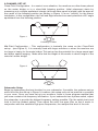
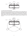
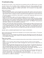
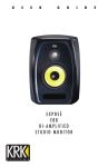
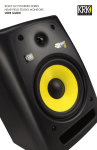
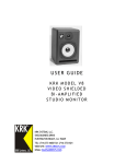
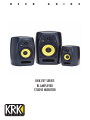
U
S
E
R
G
KRK VXT SERIES
BI-AMPLIFIED
STUDIO MONITOR
U
I
D
E
2
Introduction
Congratulations on your KRK purchase! And welcome to the growing family of KRK
owners.
KRK’s VXT Series of powered studio monitors are precision speakers designed to
forever change the way you handle your most demanding audio jobs. VXT means truth in
French and that’s just what these monitors are all about - they reveal the truth in your audio
material.
The VXT monitors feature key design elements that continue to make the KRK sound a
“studio standard”. The series was created using stringent design philosophies similar to
KRK’s flagship close-field monitor, the Exposé.
The VXT Series includes new custom made woofers and tweeters, a curved front panel for
improved imaging, a new cabinet design that provides improved structural integrity and
extended low end and slotted ports that greatly reduce port turbulence. What’s more, we’ve
provided valuable and practical features like an improved speaker protection circuit for
added confidence and new drivers for extended frequency response.
The result is a studio reference monitor that you can trust, delivering defined low end,
articulate midrange, and precise, natural highs.
Whether you are making critical mixing decisions or need to capture the subtle nuances of
a unique sound, you’ll quickly discover that the VXT Series is as precise about your work
as you are.
This manual is intended to inform you of the many features of your new VXT monitors and
their operation. We encourage you to take a few minutes to familiarize yourself with this
manual. Thank you for choosing KRK!
IMPORTANT NOTE: Your VXT monitor was originally packaged in a specially
designed carton. Please save these items. They should be used when transporting
or shipping your monitors.
3
Design Philosophy
A studio monitor is a tool used to aurally “measure” the changes in an audio path. Ask any
seasoned recording professional what they think makes a great studio monitor and you’ll
get basically the same answers: “Accuracy, transparency, flat response, and the truth.”
Simply put, recording engineers want the electrical signal entering their monitor to be
reproduced mechanically by the transducers and they want this to occur without any
deviation or compromise to the original signal. Professionals depend upon their monitors to
deliver their artistic vision in a way that will translate as accurately as possible to a
variety of audio mediums. Technically, this is accomplished by designing a monitor that
addresses three critically important criteria: Spectral Balance, Distortion Management, and
Resonance Management.
1. Spectral Balance (Timbre)
Research confirms that proper spectral balance is important for a studio monitor.
Spectral balance is defined by:
• Smooth on-axis response
• Smooth octave to octave response
• Smooth off-axis response
From years of listening to feedback from some of the top engineers and producers, KRK
engineers have come to understand how a properly tuned monitor can become a valuable
recording tool.
The VXT monitors have been designed to be as flat as possible so that what you hear
represents the true nature of the audio material without coloration or enhancement. You
can be confident in the fact that your mixes will be accurate and phase coherent.
2. Distortion Management
Any loss or addition to the audio signal is a distortion and this can occur in the speakers
themselves. The VXT series has very low speaker distortion which, of course translates into
improved reproduction accuracy.
Various amplifier distortions have been eliminated as well; the most common being
intermodulation, transient intermodulation, and harmonic distortion.
Distortion can also occur when the waveform is impacted by physical conditions such as
port turbulence and diffraction. KRK engineers have implemented design concepts that
eliminate or minimize these damaging conditions.
3. Resonance Management
Resonance is the tendency of something to vibrate at a particular frequency after the
source of energy is removed.
Resonances also play a major role in impacting the performance of a speaker. KRK design
elements minimize driver and enclosure resonance.
4
Design Elements
New Custom Made Tweeter and Woofer Designs – KRK is renowned for designing high
performance studio monitor drivers. Your VXT monitors are no exception. A woven Kevlar® low
frequency driver was custom-designed specifically for each model. Kevlar® is one of the
strongest, lightest, most rigid materials that can be used in modern speaker cone construction.
Kevlar’s unique physical properties minimize axial or conical break up modes. Both tweeters and
woofer provide faster attack times. The new tweeters provide enhanced high frequency
extension with improved distortion characteristics.
Resonant Free Extended Low Frequency Enclosure Design - The cabinetry of your VXT
monitor is constructed from ABS Structural Foam which provides stronger structural
integrity compared to cabinets made from standard ABS solid materials. Because of the
increased strength of this process, the cabinet walls can be thinner than would be from using
MDF, increasing the interior volume of the cabinet which equates to extended low
frequency response. Structural foam also provides enhanced dampening characteristics which
greatly reduces cabinet resonance.
New cabinet design provides many benefits – Due to the radical design of the cabinet, your VXT
monitors are manufactured using ABS Structural Foam. The Cabinet has inner and outer walls
with a lightweight foam filling. ABS Structural Foam has many advantages over the
standard ABS enclosure. One advantage is the Cabinet can be made with thicker walls. Having
the foam between the inner and outer hard shells acts as a damper and reduces the potential of
resonances. Another advantage is that the walls can be thinner than they would be in MDF. This
allows for more internal volume allowing the system to extend its lower frequency capability. The
third advantage is that there are no parallel internal walls. This eliminates standing waves and
or nodes which are extremely detrimental to the internal and external acoustical response of an
enclosure. These characteristics aid in eliminating the cabinet from potentially coloring the
sound of the speaker system.
Active Filter Crossovers - The VXT series power amplifiers contains three active filters.
(Subsonic, low-pass and high-pass filter) These three filters work together to provide a
seamless integration of the driver components ensuring a smooth spectral balance.
Bi-amplifier Design– KRK’s amplifier consists of audiophile grade components and a
simple audio path for transparency. Output power is balanced to match LF and HF driver
sensitivities and power handling. Your VXT monitors use a toroidal power transformer for low
hum and minimum noise.
Contoured Faceplate – Like the KRK flagship close-field monitor, the Exposé, all cabinet edges
and port openings are heavily contoured to reduce diffraction resulting in better detail and stereo
imaging. The curved faceplate offers improved off axis dispersion aiding in off axis imaging
Slotted Ports – Slotted ports reduce the port turbulence and distortion commonly found in
poorly designed round ports.
Defeatable Limiter - The monitors contain a limiter circuit which provides improved
protection. The Default setting for this switch will be in the OFF position. The limiter is designed
to mitigate the negative effects of over driving the amplifier and or the speaker’s drivers. The limiter, when engaged, can greatly reduce the risk of harming a driver. It can however be defeated
using the “Clip Indicator/Limiter Switch” on the rear panel. This is only recommended if you are
using your monitors well within their limitations. Use the indicator on the front baffle to help
determine the optimum level without audible distortion.
5
Back Panel Features
SYSTEM LEVEL ADJUST
Input sensitivity is adjusted (counterclockwise reduces
sensitivity) through a rear panel mounted trim control.
Adjustment range is from -30dB to +6dB. Factory preset
gain is +6dB, which should suffice for most conditions.
Normally adjustments would only be made if you’re using
your VXT monitors in a surround system and you need to
balance levels or if your monitor-source is too hot and not
adjustable.
HF ADJUSTMENT (VXT 6 and VXT 8 ONLY)
High Frequency Adjustment is through a rear panel mounted 3-position toggle switch.
Range of control is +1dB, Flat, or -1dB shelving above 2 kHz. Factory setting is flat
(toggle switch is in middle position). Room acoustics may dictate which type of adjustment
you need to make to retain the proper frequency response from the monitor.
LF ADJUSTMENT (VXT 6 and VXT 8 ONLY)
This 3-way switch adjusts the low-frequency response of the monitors. Proximity to walls
can add undesirable low frequency content. Adjust the LF Adjustment switch to
compensate for exaggerated low frequency response. Room acoustics may dictate which
type of adjustment you need to make to retain the proper frequency response from the
monitor.
The three-way toggle switch provides the ability to adjust the low frequency when the monitors are
effected by by room boundaries such as walls and corner locations. The setting labeled WHOLE
refers to the term "Whole Space" and is used to provide the most bass response. QUARTER refers
to quarter space and rolls off the most low frequencies. HALF refers to "Half Space" and provides a
setting in between no roll off and QUARTER space roll off. Your monitors come from the factory set
to WHOLE space. Read further in this document for more advice on set up.
6
Lift/GND Switch
Engaging the ground lift switch can sometimes reduce ground loop noise in your system.
By providing an AC mains ground on the VXT and proper installation in a 'quiet studio'
environment, the system is happily quiet.
However, noise will be induced if the monitor is installed in less than desirable settings (i.e.
audio cables run alongside power cables, behind refrigerators, near florescent lighting,
older buildings with bad wiring), or with certain equipment with lots of RFI (lap-top supplies,
PCs, generator supplied AC lines). This is because there is a ground loop through the sub
panel, mains wiring, source, and back to the subwoofer on Pin-1 of the Audio inputs.
Ground currents traveling through this loop impose different voltages along the path at
different gain stages within the circuitry, thus creating noises.
The Ground lift switch does not affect the AC mains/panel safety ground. It does not 'open'
the connection thru Pin-1 to the panel, but increases the resistance (from zero ohms to one
thousand ohms) to reduce the ground current and induced noises. Safety is not affected.
Clip Indicator/Limiter Switch
The Clip Indicator/Limiter switch allows you to choose between three options.
1. In the On position the clip led (RED) is active and the limiter is bypassed. At the onset
of the red LED illuminating, the amplifier is close to clipping. When the red LED blinks
occasionally and lightly no damage is occurring to your monitor. If the red LED is lit for
extended periods of time please turn down the input signal to your monitors to avoid
damage! The clip indicator can be a preferred setting while tracking or mixing at louder
volumes to indicate the potential for excessive volumes that can damage your monitors.
2. In the “Off” position the clip LED is inactive and the limiter is bypassed.
3. In the “Limit” position the signal is routed through the Limiter circuit and the signal is
limited when a predetermined threshold is passed. When the limiter is activated by
overdriving the amplifier, the led will illuminate. The duration and intensity of the green LED
will increase as limiting increases. It is not recommended to mix with the limiter activated
as the limiting of the audio signal will change the characteristics of the audio. If you are
finding that you need to activate the limiter for mixing, then it is recommended to instead
turn your system down to limit overdriving the audio signal.
Connecting Your System
POWERING ON
All connections should be made, all faders and controls should be set at their minimum
levels, and all other equipment should be powered on prior to powering on your V8
monitors.The power On/Off switch is located on the rear pane. The KRK Logo on the front
baffle illuminates when the power is applied.
Audio Mute Switch
Placing this switch in the ON position activates a timing circuit whereby the High Voltage
Power Supply is shut off after approximately 20 minutes if no audio signal is detected. The
Low Voltage Power supply is still drawing current. The monitor will unmute when signal is
detected.If you are working with very low level or intermittent material such as audio for
games or surround mixing, it is recommended to leave the auto mute switch off.
7
NEUTRIK® COMBO CONNECTOR
The Neutrik® Combo connector accommodates
XLR, 1/4” TRS and 1/4” phone plugs. Please note
that PIN 2 is hot!
If you are using an
unbalanced connection make sure to wire Sleeve
and Ring together at the source end. This can be
accomplished by using the appropriate cable or
adapter.
Installing Your Monitors
The close-field monitor, by definition, reduces room interaction. This can be compared to
the conventional stereo configuration or the large monitor arrangement in a recording
studio where sounds emanating from the monitor or reflecting off ceilings, walls, and floors
greatly affect the sound quality. By shortening the path to the ear, the close-field monitor
offers a tremendous amount of flexibility, allowing the sound to become less susceptible to
differing room conditions. The ability to adjust the high and low frequency characteristics is
equally important to help compensate for room irregularities and achieve the highest sound
accuracy. (See HF Adjustments and LF Adjustments sections in this manual. Note- These
adjustments are only available on the VXT 6 and VXT 8 .)
A room that is heavily dampened would typically require a high frequency boost. Likewise,
reducing the high frequencies can alter a reverberant room. The low frequency can be
adjusted to compensate for the first reflection (bounce) off the woofer, whether it comes
from the floor, as in the typical stereo setup, or from the surface of the mixing board (when
the monitor is placed atop the meter bridge).
Placing the monitor close to a rear wall, sidewall, or a corner will reinforce the low
frequencies. Generally speaking, if you move them two to three feet away from walls and
corners, you'll hear less low frequency interaction (excluding any interaction with the
mixing console). But when ideal positioning isn't practical, low frequency control is the
solution. Lets say you have two different studios in your facility; in one room the monitors
are close to the wall, in the other they're further away from the wall. Simply adjust the low
frequency on each monitor and you'll have the same sound in each room. This comes in
handy if you're tracking in room A and mixing down in room B.
Positioning Your Monitors
Positioning the monitors correctly in the studio is critical to their performance. Basically,
they should be placed in such a way that the listening position is fully “covered” with all
speakers resting on the same horizontal plane. A good way to test the monitor for its
imaging capability is to play back a CD that you are very familiar with. You can adjust the
angle of each speaker by listening for dead spots—where you'll notice an immediate
decrease in high frequency content.
8
2-CHANNEL SET-UP
Close-Field Configuration - In a control room situation, the monitors are often times placed
on the meter bridge or in a close-field listening position. Initial placement starts by
measuring out a simple equilateral triangle (all three sides equal in length) with the apex at
the center of the listening position (as shown in Figure 1) as an "overlay" for the stereo
installation. In this configuration, the Left and Right monitors are each placed at a 60º angle
equidistant from the listening position.
Figure 1
Listening Position
Mid-Field Configuration – This configuration is basically the same as the Close-Field
set-up. (see Figure 2) It is normally used with larger monitors or when the monitors are
too large or heavy for the meter bridge. This set-up has the potential for a larger sweet spot
and better spatial imaging. Make sure that the height of the woofer is above height of the
console’s meter bridge.
Figure 2
Subwoofer Setup
Begin by determining the best location for your subwoofer. If possible, the optimum set-up
would look like the set-up in Figure 3; however, this setup may not be practical or possible
in your room. Once you have set up your monitors, listen to some program material that
you know contains low frequency information. If your subwoofer has a phase switch, adjust
the subwoofer to provide the highest frequency setting possible. Flip the switch back and
forth to find the loudest setting. Then adjust the sub's low pass filter so that it works in
conjunction with the satellite's high pass frequencies, the readjust the level of the sub.
9
Figure 3
5.1 Channel Surround Sound Setup
Begin by placing the Left and Right front channels 30 degrees from the Center channel and
equidistant to the listening position (Figure 4). The Left Surround (rear) and Right Surround
(rear) channels should be placed 110 degrees from the Center channel. Their location
should also be equidistant from the listening position. The subwoofer (Low Frequency
Effects) channel is most effective when situated directly below the Center channel (as
shown in Figure 4). If this is not possible, place the subwoofer just to the right or left side
and below the Center channel. Ensure that the woofers are above the height of the
console.
Figure 4
10
7.1 Channel Surround Sound Setup
The 7.1 channel surround sound setup adds two speakers to the sides of the mix position
and is most similar to the actual surround sound configuration of cinema—with the
difference being that cinemas commonly add additional side surrounds to compensate for
the length of the theater.
The front Left and Right speakers typically form a wider triangulation (in relation to the mix
position) than that of a 5.1 setup so as to more accurately replicate the fact that in cinema,
the front speakers are not angled toward the center, but rather face straight out into the
theater—as is also the case for the mix stage in film sound mixing. The Center channel
loudspeaker is positioned directly in the center as is the case in a 5.1 surround setup.
Similarly, the subwoofer is most effective when situated directly below the center channel.
If this is not possible place the subwoofer just to the right or left side and below the Center
channel.
Like the three front speakers, the Left and Right surround speakers are positioned at
equidistance from the mix position directly to the sides. Finally, the Left and Right rear
surround speakers are placed behind the mix position at equidistance to the mix position.
The 7.1 channel surround sound environment is one of total immersion, and is the best
choice for mix environments where sound needs to be detectable side to side, along with
front to rear.
Once the monitors have been placed, you’ll need to adjust the System Gain pots for each
monitor so that all channels have exactly the same SPL output at the listening position.
Although this can be done simply by listening to each channel one at a time and adjusting
for relative levels, we recommend using an SPL meter and filtered noise (pink noise) to test
each channel independently. Simply take a reading from each monitor, and then adjust all
the monitors to match your lowest SPL reading. Your system levels should now be
balanced for multi-channel surround.
Figure 4
11
Troubleshooting
We welcome your input. If you should have any problems with your KRK monitors, we want
to hear about it. You can either email us (please provide your phone number with your
email) or contact our technical support department directly at 954-949-9600. We're
constantly striving to better our already high quality. Your comments are appreciated.
E-mail: [email protected]
There is no power.
• Check to see if the power cord is plugged into both the IEC socket on the rear panel of
the active speaker and into the AC mains. Verify that the AC mains are active by using an
approved AC tester or simply connect a lamp with working light bulb. In some cases, the
AC mains may be controlled by a light switch or power strip suppressor that may not be
in the ‘on’ position.
• Verify that the power switch on the active speaker is in the ‘on’ position.
• Check to see if the AC mains voltage is matched to the correct operating voltage
requirements. If the AC mains voltage is higher than the selected voltage it is possible that
the fuse needs to be replaced. For example, if the AC mains voltage is 240VAC and the
selected voltage on the active speaker is set incorrectly to ‘110-120VAC’, than the fuse
will break to protect the active speaker electronics.
• Check to see if the power light is illuminated. The power light can often to be found on the
front panel of the monitors and the rear panel of the subwoofers. The power light is part
of the triangle contained in the ‘KRK’ logo. If the power light is not illuminated, turn the
power switch OFF and check the A/C mains fuse(s). The fuse is located directly below the
power receptacle. Please see the user guide that came with your monitor for more information.
NEVER USE A LARGER AMPERAGE FUSE THAN IS SPECIFIED!
After the fuse has been checked and replaced, turn the power switch back on. The power
light should illuminate.
• Check to see if a fuse change was needed and upon powering the monitor back up the
fuse(s) blow again, the monitor needs to be returned to the dealer where you purchased
it or to KRK for servicing.
There is no sound.
• Repeat steps in the previous troubleshooting section above before continuing to the next
steps.
• Check to see if all other audio devices using the same AC outlet are still operating.
• Check to see if the audio source cable is plugged into both the source output and the
monitor input.
• Check to see if the System Gain pot is turned up fully clockwise. The System Gain pot on
monitor models E8B, VXT and ROKIT2 series should be set to + 6 dB. For all other models not mentioned please consult the user manual that came with the product.
• Check to see if the signal source (E.g. mixing console, work station, CD player, etc.) is
turned up to a level that can properly send a signal to the monitors.
• Check to see if one of the monitors is working. Exchange the audio input cable from the
non-working monitor to the working unit. This will determine whether it's really the
monitor, a faulty cable, or some other glitch in the audio chain.
• If the monitor is still not responding, it should be returned to the dealer where you
purchased it or to KRK for servicing.
12
Monitor suddenly stops working.
• Turn the monitor level down or off
• Repeat steps in the troubleshooting sections above before continuing to the next steps.
• Carefully check to see if the amplifier's back plate is hot! If the monitor has been running
at highest power output for an extended period of time, it could be that the unit has
become overheated and the protection circuitry has shut the system down momentarily.
The monitor provides maximum circuitry protection against AC power surges, amplifier
overdrive, and overheating of the amplifiers. Turn the monitor off then wait 30 minutes to
allow the back plate to cool down. Turn the power switch back on.
• Increase the volume to check for normal operation.
• If the monitor is still not responding, it should be returned to the dealer where you
purchased it or to KRK for servicing.
Sound quality changes.
• Repeat steps in the previous troubleshooting section above before continuing to the next
steps.
• It is possible that the change in sound quality is due to changes in the room or listening
position. Low frequencies (bass response) can be increased or reduced by changes such
as furniture and/or large equipment placement. Try moving the speakers or listening area
a different position or return the room back to where the sound quality was acceptable.
• Disconnect the signal cable at the input of the monitor and adjust the System Gain or
volume control to the minimum setting. With power on, place your ear close to each
driver (tweeter/woofer) and listen for noise (i.e., a slight hiss or hum) while slowing
increasing the System Gain setting from the minimum setting. It is important that the
System Gain is slowly adjusted from minimum setting to avoid any spike in sound levels
while the ear is close to the driver (tweeter & woofer). If there's absolutely no sound
whatever, it could be that one or more of the drivers (woofer or tweeter or both) is at fault.
It's also possible that the problem lies somewhere in the electronics.
• Play some non-distorted source material at a low volume. Carefully cover the tweeter (to
block the sound) without touching the diaphragm. Is the woofer producing a clean sound?
If there is not a clear tonal quality or any sound at all then the woofer probably needs to
be replaced.
• Cover the woofer so you can hear mostly the tweeter. Is the tweeter producing a clear
sound? If there is not a clear tonal quality or any sound at all then the tweeter probably
needs to be replaced.
• Verify the source signal level has not changed or source has changed. This can be
tested by connecting the source headphone outputs to a set of headphones and verifying
the sound is not loud or distorted. If the sound is poor at the source (preamp stage) than
it is not the active speakers.
• Once you have a better idea of what may be at fault then call us and speak with
someone in the service department. They will help you determine the best solution to
correct your monitors. The service department can be reached at 954-949-9600.
13
Monitor hisses, hums or makes other loud noises.
• Make sure that the power cord is plugged snugly into the IEC socket on the rear of the
monitor.
• Check the connections between the signal source and the monitor. Make sure all
connections are secure and that the cable is not damaged or wired incorrectly.
• If you are using an unbalanced output to balanced cable conversion, make sure it is
correct. The shield is connected to the unbalanced ground of the source and pins 1 and
3 of the XLR (or the sleeve and ring on the ¼” TRS jack).
• All audio equipment should use the same ground point. Check all other devices using the
same AC output in the building like light dimmers, neon signs, TV screens, and
tcomputer monitors. These devices should not be using the same circuit.
• Verify that the signal cables are not routed near AC power lines or other EMI sources
(including wall power adapters and computers).
• Excessive hiss may be a result of an incorrect gain setting before the speaker connection.
Verify the source signal is not noisy before connecting the monitors. This can be tested
by connecting the signal source headphone outputs to a set of headphones.
Please read the warranty card that was included in the shipping carton of your monitor prior
to shipping it back to KRK Systems, LLC. All products in need of repair can be returned to
the dealer where it was purchased, or to the following address:
KRK Systems, LLC.
772 S. Military Trail
Deerfield Beach, FL 33442
Phone: +1 954-949-9600
Fax: +1 954-949-9590
E-mail: [email protected]
Please call for a Return Authorization number before returning any product for repair. The
service department can be reached at 954-949-9600 or email [email protected] along
with the following information:
•
•
•
•
•
•
Your Name
Your Address
Phone Number
Model Number
Serial Number
Description of the problem
For the safest possible return to KRK, please use the shipping carton and packaging that
your monitor was originally shipped in.
KRK cannot be responsible for any damages incurred during the shipping process due to
poor packing. Make sure to insure your shipment.
If your monitor is out of warranty and you would like a quotation prior to servicing your product, please include a note with your contact information on it and we will contact you with a
service quote. Service will be performed once your method of payment has been established and approved.
For replacement part quotes call 954-949-9600.
14
Specifications
Model
VXT 4
VXT 6
VXT 8
&RQÀJXUDWLRQ
:D\
:D\
:D\
6\VWHPW\SH
$FWLYH6WXGLR0RQLWRU
$FWLYH6WXGLR0RQLWRU
$FWLYH6WXGLR0RQLWRU
/RZ)UHTXHQF\
:RYHQ.HYODUZRRIHU
:RYHQ.HYODUZRRIHU
:RYHQ.HYODUZRRIHU
0LG)UHTXHQF\
N/A
N/A
N/A
+LJK)UHTXHQF\
VLONGRPHWZHHWHU
VLONGRPHWZHHWHU
VLONGRPHWZHHWHU
)UHTXHQF\5HVSRQVH
+]N+]G%
+]N+]G%
+]N+]G%
0D[3HDN63/
G%
G%
G%
$PSOLÀHU&ODVV
&ODVV$%
&ODVV$%
&ODVV$%
3RZHU2XWSXW
45W
90W
180W
+LJK)UHTXHQF\
15W
:
60W
0LG)UHTXHQF\
N/A
N/A
N/A
/RZ)UHTXHQF\
:
60W
120W
,QSXW,PSHGDQFH2KPV
.2KPEDODQFHG
+)/HYHO$GMXVW
+)6KHOI
N/A
/)/HYHO$GMXVW
.2KPEDODQFHG
.2KPEDODQFHG
G%VKHOI)ODWG%VKHOI
G%VKHOI)ODWG%VKHOI
N/A
N/A
ZKROHKDOITXDUWHU
ZKROHKDOITXDUWHU
6\VWHP9ROXPH
G%G%
G%G%
G%G%
$XWR0XWH
RQRII
RQRII
RQRII
,QGLFDWRUV
3RZHU&OLS/LPLW
3RZHU&OLS/LPLW
3RZHU&OLS/LPLW
,QGLFDWRU&RQWURO
&OLS,QGLFDWRU2Q2II/LPLW
&OLS,QGLFDWRU2Q2II/LPLW
&OLS,QGLFDWRU2Q2II/LPLW
,QSXW&RQQHFWRUV
5&$
N/A
N/A
N/A
1/4"
%DODQFHG;/5&RPER
%DODQFHG;/5&RPER
%DODQFHG;/5&RPER
;/5
%DODQFHG;/5&RPER
%DODQFHG;/5&RPER
%DODQFHG;/5&RPER
*URXQG/LIW
2Q2II
2Q2II
2Q2II
$&3RZHU,QSXW
6HOHFWDEOH999
9+]+]RU9
+]+]
6HOHFWDEOH999
9+]+]RU9
+]+]
6HOHFWDEOH999
9+]+]RU9
+]+]
(QFORVXUH&RQVWUXFWLRQ
6WUXFWXUDO)RDP
6WUXFWXUDO)RDP
6WUXFWXUDO)RDP
)LQLVK
%ODFN7H[WXUHG3DLQW
%ODFN7H[WXUHG3DLQW
%ODFN7H[WXUHG3DLQW
3RUW&RQÀJXUDWLRQ
)URQWÀULQJVORWSRUW
)URQWÀULQJVORWSRUW
)URQWÀULQJVORWSRUW
*ULOOH
2SWLRQDO
2SWLRQDO
N/A
0RXQWLQJ
%RWWRP
%RWWRP
%RWWRP
&RPSDWDEOH2PQL0RXQW
:%;
:%;
:%;
'LPHQVLRQV+[:['
PP[PP
[PP
PP[
PP[PP
PP[
PP[PP
:HLJKW
/EV.J
/EV.J
/EV.J
15
LITK00023