1
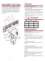
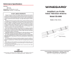
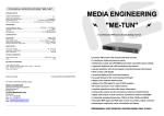
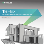
Performance Specifications
Channels:
VHF: 2-13
UHF: 14-69
Dimensions: 5”H x 26-3/4”W x 4-1/4”D
Amplifier Gain: VHF/UHF: 7-10 dB average
90 DAY LIMITED WARRANTY
Winegard Company warrants this Winegard product (excluding receiver) against
any defects in materials or workmanship within two (90) day from date of purchase. No
warranty claim will be honored unless at the time the claim is made, you present proof
of purchase to an authorized Winegard dealer (if unknown, please contact Winegard
Company, 3000 Kirkwood Street, Burlington, Iowa 52601-2000, telephone 319-7540600).
Winegard Company (at its option) will either repair or replace the defective product
at no charge to you. This warranty covers parts, but does not cover any costs incurred
in removal, shipping or reinstallation of the product. This limited warranty does not
apply if the product is damaged, deteriorates, malfunctions or fails from: misuse,
improper installation, abuse, neglect, accident, tampering, modification of the product
as originally manufactured by Winegard, usage not in accordance with product
instructions or acts of nature such as damage caused by wind, lightning, ice or
corrosive environments such as salt spray and acid rain.
The 90 day Warranty is provided on the condition that the equipment is properly
delivered with all handling and freight charges prepaid to your Winegard dealer for
repair or return to our factory at the above address. Winegard dealers will arrange for
the replacement or repair and return to you, without charge, the product which failed
due to defective material or workmanship.
WINEGARD COMPANY WILL NOT ASSUME ANY LIABILITIES FOR ANY OTHER
WARRANTIES, EXPRESS OR IMPLIED, MADE BY ANY OTHER PERSON.
ALL OTHER WARRANTIES WHETHER EXPRESS, IMPLIED OR STATUTORY
INCLUDING WARRANTIES OF FITNESS FOR A PARTICULAR PURPOSE AND
MERCHANTABILITY ARE LIMITED TO THE TWO YEAR PERIOD OF THIS WRITTEN
WARRANTY.
The foregoing shall be the sole and exclusive remedy of any person whether in
contract, tort or otherwise, and Winegard shall not be liable for incidental or consequential
damage or commercial loss, or from any other loss or damage except as set forth
above.
Some states do not allow limitations on how long an implied warranty lasts, or the
exclusion of limitation of incidental or consequential damages, so the above limitations
or exclusions may not apply to you.
This warranty gives you specific legal rights and you may also have other rights
which vary from state to state.
Winegard Company • 3000 Kirkwood Street • Burlington, IA 52601 • 319/754-0600 Fax 319/754-0787
•www.winegard.com Printed in U.S.A. © 2005 Winegard Company 2452064
WINEGARD
®
SharpSh oter
TM
Amplified Low Profile
Indoor Television Antenna
Model SS-3000
Made in the U.S.A.
Patent Pending
Winegard Company • 3000 Kirkwood St. • Burlington, IA 52601-2000
319/754-0600 • FAX 319/754-0787 • www.winegard.com
Printed in U.S.A. © Winegard Company 2005 2452064
About Your SS-3000 SharpSh oter Antenna
Troubleshooting
Thank you for choosing the Winegard SharpSh oterTM .Winegard antennas are
designed to deliver sharp, clear, high definition signal reception. At Winegard,
our engineering department is dedicated to designing antennas that enhance
both the latest technology and the aesthetics of any viewing environment. The
SS-3000 installs in minutes, is easy to use and simple to adjust. Before using
your antenna, please remove all parts from the box and read the owners’s
manual carefully.
No picture, or the tuner is displaying no “signal.”
1. Make sure that the SharpSh oterTM is connected to the correct “antenna in”
input on the set-top box or TV.
2. Rotate the antenna around the room to find the best reflected signal,keeping
in mind that the best reflected signal may be behind the anntenna.
(See page 6 for directions on how to use the web to locate the broadcast tower
location. Rotate the antenna base up to 360° until you receive the best signal
possible).
3. For houses with aluminum siding/insulation or stucco, place the antenna near
a window to minimize interference.
TM
Reflector
Antenna
SharpSh oter Indoor Reception
Antenna Base
CHANNEL
(4) Clips
AC Adaptor
ANALOG
DIGITAL
2-6
0 - 10
0 - 15
7 - 13
0 - 20
0 - 25
14 - 69
0 - 25
0 - 30
Frequently Asked Questions
Q. What do I need to get HDTV?
A. A High Definition television with built-in or set-top HD receiver.
6’ Mini Coax Cable
(To Antenna)
2’ Coax Cable
(To TV)
79
11$
$17(
(5
32:
$
79
Power Injector
11
$17(
(5
32:
6’ Standard
Coax Cable
Q. Why do I need an antenna?
A. This antenna will get you local high definition broadcast channels proving you
live within 30 miles of the broadcast tower and there are no obstacles between
you and the broadcast tower that could interfere with reception (see note
below).
Q. Can I use this antenna in a basement?
A. No, broadcast signals cannot penetrate into basements due to their lower
elevation.
Q. How can I get channels above channel 13?
A. Tuners have both cable and antenna modes. Access the proper on screen TV
menu and switch from Cable/CATV mode to ANT/AIR mode to receive these
channels.
Please Note:
Other variables, which are not related to antenna performance, can effect your
reception. These include distance from the source transmitting the desired
station, and man-made and natural conditions.
Example: Obstacles such as buildings between the transmitting source and your
antenna.
2
7
Operating Your SS-3000
Installation
Locating your SS-3000 SharpSh oterTM Antenna
Your SharpSh oterTM is a precision instrument and should be placed in a
location that is best for receiving TV signals.
Attaching the clips to the reflector.
1. Lay the Reflector flat on the table.
2. Grip the Reflector with your thumb and index finger and bend the Reflector’s
top and bottom edges towards you. (See Fig. 2, 3)
3. With your other hand, grasp the Clip and attach it to the Reflector at the two
notches.
4. Repeat steps 2 and 3 for all four Clips.
Your SharpSh oterTM can be placed on top of any TV for ease of adjustment.
Operating your SS-3000 SharpSh oterTM
Positioning the SharpSh oterTM properly will give you optimal digital television
(DTV) reception, especially in areas of high multipath. In such areas, an antenna
reposition of a few inches could mean the difference between an excellent DTV
stream or a loss of picture.
Fig. 2
Notch
First you should point the antenna towards a window.
If this fails to give you a solid picture, slowly rotate the antenna 360 degrees
until you receive a picture - the SharpSh oterTM antenna was designed to pick
up reflected signals from interior walls. Keep in mind that the best reflected
signal may be behind the antenna.
NOTE: It is best to utilize the Signal Strength Meter of your set-top box or HDTV
television with built in tuner to optimize the position of the SharpSh oterTM
antenna.
You can use the following Web tool to find where the broadcast towers are
located from your home address:
1. Go to www.antennaweb.org and click the “Antenna Locator.”
2. Enter your home’s address and then “Submit.”
3. Click “View Street Level Map” to see which direction you should point your
antenna.
Notch
Fig. 3
Please Note:
1. Do not place your SharpSh oterTM near large metal objects or appliances
that could create interference.
2. Do not lift your SharpSh oterTM by its receiving elements or place objects on
them.
3. Late model televisions have on-screen menu controls for viewing VHF/UHF
“Off-Air” or cable broadcasts. Please ensure that this menu control is at the
proper “Off-Air” position.
6
3
Installation (cont.)
Installation
Attaching the Reflector to the Antenna
1. Starting from the right side, slide the Clip that is attached to the Reflector
diagonally into the notch at the back of the Antenna. (See Fig. 4, 5)
2. Once the Clip is pushed in, slide it to the side so that it forms a 90 degree
angle to the Antenna’s edge. (See Fig. 6)
3. Repeat steps 1 and 2 for all four Clips.
Attaching the Antenna with reflector to the Base
1. Route the 6’ Mini Coax Cable through the Base and screw it securely to the
Antenna.
2. Slide the Antenna with Reflector onto the Base.
3. Using a screw driver slightly tighten the two screws, (see Fig. 7), to secure
the Antenna to the Base.
Fig. 7
Fig. 5
Fig. 4
Connecting the SharpSh oterTM
1. Connect the Mini Coax Cable
that is attached to the Antenna
to the Power Injector labeled
“Antenna”.
2. Connect the 2’ Coax Cable
from the Power Injector
labeled “TV” to your HDTV
or Set-up box.
3. Connect the 6’ Standard Coax
Cable from the Power Injector
labeled “Power” to the AC
Adapter.
4. Plug in the AC Adapter to a
standard AC outlet.
Fig. 6
6’ Coax
Cable
79
2’ Coax
Cable
79
11$
11$
$17(
(5
32:
Fig. 8
Attaching Rubber Feet to the Base
Remove the protective adhesive
strip from the four rubber feet and
apply them to the bottom of the
antenna base.
Fig. 9
4
$17(
(5
32:
5
Feet