1
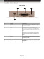
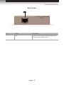
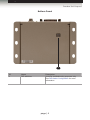
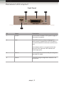
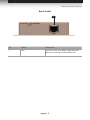
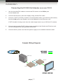
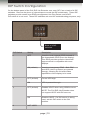
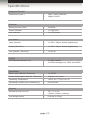
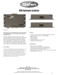
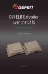
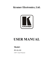
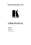
DVI
ELR Lite
3GSDI
Audio
Embedder
Extender over
one CAT-5
EXT-DVI-1CAT5-SR
User Manual
Release A1
DVI ELR Lite Extender over one CAT-5
Important Safety Instructions
GENERAL SAFETY INFORMATION
1.
Read these instructions.
2.
Keep these instructions.
3.
Heed all warnings.
4.
Follow all instructions.
5.
Do not use this product near water.
6.
Clean only with a dry cloth.
7.
Do not block any ventilation openings. Install in accordance with the manufacturer’s
instructions.
8.
Do not install or place this product near any heat sources such as radiators, heat
registers, stoves, or other apparatus (including amplifiers) that produce heat.
9.
Do not defeat the safety purpose of the polarized or grounding-type plug. A polarized
plug has two blades with one wider than the other. A grounding type plug has two
blades and a third grounding prong. The wide blade or the third prong are provided for
your safety. If the provided plug does not fit into your outlet, consult an electrician for
replacement of the obsolete outlet.
10. Protect the power cord from being walked on or pinched particularly at plugs,
convenience receptacles, and the point where they exit from the apparatus.
11. Only use attachments/accessories specified by the manufacturer.
12. To reduce the risk of electric shock and/or damage to this product, never handle or
touch this unit or power cord if your hands are wet or damp. Do not expose this
product to rain or moisture.
13. Unplug this apparatus during lightning storms or when unused for long periods of time.
14. Refer all servicing to qualified service personnel. Servicing is required when the
apparatus has been damaged in any way, such as power-supply cord or plug is
damaged, liquid has been spilled or objects have fallen into the apparatus,
the apparatus has been exposed to rain or moisture, does not operate normally,
or has been dropped.
15. Batteries that may be included with this product and/or accessories should never be
exposed to open flame or excessive heat. Always dispose of used batteries
according to the instructions.
ii
DVI ELR Lite Extender over one CAT-5
Warranty Information
Gefen warrants the equipment it manufactures to be free from defects in material and
workmanship.
If equipment fails because of such defects and Gefen is notified within two (2) years from
the date of shipment, Gefen will, at its option, repair or replace the equipment, provided
that the equipment has not been subjected to mechanical, electrical, or other abuse or
modifications. Equipment that fails under conditions other than those covered will be
repaired at the current price of parts and labor in effect at the time of repair. Such repairs
are warranted for ninety (90) days from the day of reshipment to the Buyer.
This warranty is in lieu of all other warranties expressed or implied, including without
limitation, any implied warranty or merchantability or fitness for any particular purpose, all of
which are expressly disclaimed.
1.
Proof of sale may be required in order to claim warranty.
2.
Customers outside the US are responsible for shipping charges to and from Gefen.
3.
Copper cables are limited to a 30 day warranty and cables must be in their original
condition.
The information in this manual has been carefully checked and is believed to be accurate.
However, Gefen assumes no responsibility for any inaccuracies that may be contained
in this manual. In no event will Gefen be liable for direct, indirect, special, incidental, or
consequential damages resulting from any defect or omission in this manual, even if
advised of the possibility of such damages. The technical information contained herein
regarding the features and specifications is subject to change without notice.
For the latest warranty coverage information, refer to the Warranty and Return Policy under
the Support section of the Gefen Web site at www.gefen.com.
PRODUCT REGISTRATION
Please register your product online by visiting the Register Product page under the
Support section of the Gefen Web site.
iii
DVI ELR Lite Extender over one CAT-5
Contacting Gefen Technical Support
Gefen, LLC
c/o Customer Service
20600 Nordhoff St.
Chatsworth, CA 91311
Telephone:
(818) 772-9100
(800) 545-6900
Fax:
(818) 772-9120
Email:
[email protected]
Visit us on the Web:
www.gefen.com
Technical Support Hours:
8:00 AM to 5:00 PM Monday - Friday, Pacific Time
DVI ELR Lite Extender over one CAT-5 is a trademark of Gefen, LLC.
Important Notice
Gefen, LLC reserves the right to make changes in the hardware, packaging, and any
accompanying documentation without prior written notice.
© 2013 Gefen, LLC. All Rights Reserved.
All trademarks are the property of their respective owners.
iv
3GSDI
DVI
ELRAudio
Lite Extender
Embedder
over one CAT-5
Operating Notes
•
CAT-5 cables should not exceed 200 feet (60 meters). CAT-6 cables should not
exceed 230 feet (70 meters).
•
Shielded Twisted-Pair (STP) CAT-5 or CAT-6 cabling is recommended.
However, Un-shielded Twisted-Pair (UTP) CAT-5 or CAT-6 cabling is acceptable.
Shielded cable has an advantage by providing immunity to Electromagnetic
Interference (EMI), cell phones and A/C motors.
v
DVI ELR Lite Extender over one CAT-5
Features and Packing List
Features
•
Extends DVI up to 230 feet (70 meters) over one CAT-6A cable
•
Extends DVI up to 200 feet (60 meters) over one CAT-5e cable
•
Supports resolutions up to 1080p Full HD and 1920 x 1200 (WUXGA)
•
EDID management for rapid integration of source and display
•
Enable/Disable switches for HDCP and HPD pass-through
•
Locking power supplies
•
Surface-mountable
1080P
®
Packing List
The DVI ELR Lite Extender over one CAT-5 ships with the items listed below. If any of
these items are not present in your box when you first open it, immediately contact your
dealer or Gefen.
•
•
•
•
•
1 x DVI ELR Lite Extender over one CAT-5 (Sender unit)
1 x DVI ELR Lite Extender over one CAT-5 (Receiver unit)
1 x 6 ft. dual-link DVI cable (M-M)
2 x 5V / 2.6A DC locking power supply
1 x Quick-Start Guide
vi
3GSDI
DVI
ELRAudio
Lite Extender
Embedder
over one CAT-5
Table of Contents
01
Getting Started
Sender Unit Layout................................................................................................ 2
Front Panel..................................................................................................... 2
Back Panel..................................................................................................... 3
Bottom Panel.................................................................................................. 4
Receiver Unit Layout.............................................................................................. 5
Front Panel..................................................................................................... 5
Back Panel..................................................................................................... 6
Installation.............................................................................................................. 7
Connecting the DVI ELR Lite Extender over one CAT-5������������������������������ 7
Sample Wiring Diagram................................................................................. 7
02Appendix
DIP Switch Configuration..................................................................................... 10
Specifications........................................................................................................11
viii
DVI ELR Lite
Extender over
One CAT-5
01 Getting Started
Sender Unit Layout................................................................................................ 2
Front Panel..................................................................................................... 2
Back Panel..................................................................................................... 3
Bottom Panel.................................................................................................. 4
Receiver Unit Layout.............................................................................................. 5
Front Panel..................................................................................................... 5
Back Panel..................................................................................................... 6
Installation.............................................................................................................. 7
Connecting the DVI ELR Lite Extender over one CAT-5������������������������������ 7
Sample Wiring Diagram................................................................................. 7
Getting Started
Sender Unit Layout
Front Panel
2
3
4
1
ID
Name
Description
1
5V DC
Connect the included 5V DC power supply to
this power receptacle.
2
Link
This LED indicator will glow bright green
when power is applied and a CAT-5 cable is
connected between the Sender and Receiver
unit.
If the source is not connected to the Sender
unit, then this LED indicator will flash bright
green.
3
DVI In
Connect the DVI source to this port using the
included DVI cable.
4
Power
This LED will glow bright blue when the unit
is powered.
page | 2
Getting Started
Sender Unit Layout
Back Panel
1
ID
Name
Description
1
Link
Connect a CAT-5 cable from this jack to the
Link jack on the Receiver unit.
page | 3
Getting Started
Sender Unit Layout
Bottom Panel
1
ID
Name
Description
1
DIP switches
Used for troubleshooting purposes only.
See DIP Switch Configuration for more
information.
page | 4
Getting Started
Receiver Unit Layout
Front Panel
2
3
4
1
ID
Name
Description
1
5V DC
Connect the included 5V DC power supply to
this power receptacle.
2
Link
This LED indicator will glow bright green
when power is applied and a CAT-5 cable is
connected between the Sender and Receiver
unit.
If the display (sink) is not connected to the
Receiver unit, then this LED indicator will
flash bright green.
3
DVI In
Connect the DVI source to this port using the
included DVI cable.
4
Power
This LED will glow bright blue when the unit
is powered.
page | 5
Getting Started
Receiver Unit Layout
Back Panel
1
ID
Name
Description
1
Link
Connect a CAT-5 (or better) cable from this
jack to the Link jack on the Sender unit.
page | 6
Getting Started
Installation
Page Title
Connecting the DVI ELR Lite Extender over one CAT-5
1.
Use the included DVI cable to connect the DVI source to the DVI In port
on the Sender unit.
2.
Connect the Receiver unit to the display using another DVI cable.
3.
Connect a CAT-5 (CAT-5e or better is recommended) cable, up to 200 feet (60 meters)
from the Link jack on the Sender unit to the Link jack on the Receiver unit.
If CAT-6a cable is being used, then the cable length can be up to 230 feet (70 meters).
4.
Connect the included 5V DC locking power supplies to the Sender and Receiver unit.
Do not overtighten the locking power connectors.
5.
Connect the AC power cord from the power supply to an available electrical outlet.
Sample Wiring Diagram
CAT5 CABLE
DVI CABLE
DVI Source
Receiver
Sender
DVI Display
EXT-DVI-1CAT5-SR
page | 7
DVI ELR Lite
Extender over
One CAT-5
02Appendix
DIP Switch Configuration..................................................................................... 10
Specifications........................................................................................................11
Appendix
DIP Switch Configuration
On the bottom panel of the DVI ELR Lite Extender over one CAT-5 are a bank of 4 DIP
switches. Remove the piece of colored tape to reveal the DIP switch bank. These DIP
switches provide control over EDID management, Hot-Plug Detect, and HDCP.
DIP switch 4 is not used. These DIP switches are used for troubleshooting purposes, only.
Bank of 4 DIP
switches
DIP Switch
Setting
Description
1
OFF
Uses the local (internal) EDID instead of
the downstream EDID (from the display).
This EDID provides generic video/audio
support which is compatible with most
displays.
ON (default)
Uses the downstream EDID. Both DDC
and HPD (Hot-Plug Detect) are passed
through, allowing the full audio/video
capabilities of the display to be used.
OFF (default)
Forces HPD high.
ON
HPD is passed through.
OFF (default)
Enables HDCP when using HDMI sources.
2
3
NOTE: The DVI ELR Lite Extender does
not support HDCP with DVI sources.
ON
4
Disables HDCP. If a DVI source is being
used, set this DIP switch to the ON
position.
NOT USED
page | 10
Appendix
Specifications
Supported Formats
Resolutions (max.)
•
•
1920 x 1200 (WUXGA)
1080p Full HD
Maximum Pixel Clock
•
165 MHz
Power Indicator
•
1 x LED, blue
Link Indicator
•
1 x LED, green
Input (Sender)
•
1 x DVI-I, 29-pin, female (digital only)
Output (Receiver)
•
1 x DVI-I, 29-pin, female (digital only)
Link (Sender / Receiver)
•
1 x RJ-45
•
4 x DIP switches
for EDID management, HPD, and HDCP
Power Input (Sender / Receiver)
•
1 x 5V DC
Power Consumption (Sender / Receiver)
•
10W per unit (max.)
Operating Temperature
•
+32 to 113 °F (0 to +45 °C)
Operating Humidity (non-condensing)
•
0 to 90% RH
Dimensions (W x H x D)
•
4.3” x 1” x 4.3”
(110mm x 26mm x 86mm)
Unit Weight (each)
•
0.36 lbs (0.16 kg)
Electrical
Connectors
Control
DIP Switches (Sender unit)
Operational
Physical
page | 11
Stretch it, Switch it, Split it, Control it.
Gefen’s got it. ®
20600 Nordhoff St., Chatsworth CA 91311
1-800-545-6900 818-772-9100 fax: 818-772-9120
www.gefen.com [email protected]
Pb
This product uses UL or CE listed power supplies.