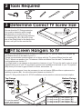
1
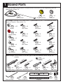
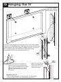
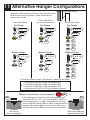
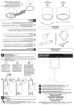
L8500
STOP
English language
Leaflet No. 462983 rev 03
Read through ALL instructions before commencing installation.
If you have any questions about this product or issues with installation
contact the customer services helpline before returning this product to
the store. See www.avfgroup.com/unimax for instruction video.
CUSTOMER SERVICES HELP LINE NUMBER:
01952 670009
0870 0609777
176lbs
80kg
80"
203cm
AVF Group Ltd. Road 30. Hortonwood Ind Est, Telford, Shropshire, TF1 7YE, England
1 Boxed Parts
You will not need all these parts, so expect there to be some left over depending upon the
specification of your TV.
A
B
- x2
Wall Bracket
C
- x2
Hanger (Yellow)
- x2
Stand-off
TV Fixings: Parts go on the back of the TV (specification of your TV will determine which
ones you require - see section 11).
D1
F1
- x12
Spacer
D2
F2
- x4
M4 16mm
M4 25mm
- x4
M4 45mm
- x4
F4
Spacer (Red)
F5
- x4
M5 16mm
E1
F3
- x4
F6
- x4
M5 25mm
- x4
M5 45mm
- x4
M4 Adaptor
F7
E2
F8
- x4
M6 16mm
- x4
F9
- x4
M6 25mm
- x4
M6 45mm
M5 Adaptor
E3
F10
- x4
M6 Adaptor
F11
- x4
M8 16mm
F12
- x4
M8 25mm
- x4
M8 45mm
Wall Fixings: Parts to attach to the wall (type of wall will determine which fixings you
require).
I - x12
m
m
m
Lock Nut
05
mm
0m
1
5
7
x
2
x
2x
.14
14
.
1
o
.
o
N
N
No
H
- x6
J
K
- x6
- x2
Long Wall Plug Long Screw Metal Stud Screw
L
- x6
Wall Plug
M
G
- x6
Screw
- x6
Wall fixing
Included Tools
P1
N
3mm Hex Key
O
18mm Wood Drill
P2
Template
Q
Level
2 Tools Required
3 Determine Correct TV Screw Size
Choose from the TV Fixings selection.
You need to determine which length
and diameter of screws fits your TV.
To determine the correct screw diameter,
try screwing (F2), (F5), (F8) & (F11) into
one of the fixing holes on the back of the
screen until you find the one that fits.
F2, 5 ,8, 11
4 Fit Screen Hangers To TV
Once you have established which screws you need for your TV, you can attach the Hangers (B)
and Stand-offs (C) to the back of your TV.
Typical recommended example shown is for fixings with the TV spaced 20mm from the wall.
The TV Mount can position your TV between 12mm and 40mm from the wall. For alternative
configurations see section 11.
You might need to use spacers to increase the clearance of your TV from the wall in order to avoid
cables coming out of your TV and improve access and ventilation to the back of your TV (spacers
(D1) allow you to have a gap of 20mm or 40mm, see section 11).
In certain circumstances it may be necessary to use red spacer (D2) as either a replacement or
addition to spacer (D1), for more information please see section 11.
If your TV fixing centres don’t fit, STOP installation and contact the customer services helpline.
Bottom Fixings
Top Fixings
F2, 5 ,8, 11
E1, 2, 3
F2, 5 ,8, 11
E1, 2, 3
* If Required
B
C
D1
D1
TV must be parallel
to wall. Use spacers /
stand-offs as shown.
*
using screw (F ) use Adapter (E )
* IfIf using
screw (F ) use Adapter (E )
2
1
5
2
If using screw (F8) use Adapter (E3)
If using screw (F11) No Adapter required
5 Assemble Positioning Template
The horizontal part of the positioning template is used to mark out
where you need to drill the mounting holes on your wall. The vertical
part is just a guide to allow you to see how high up the wall your TV
will be to help you find the perfect position for viewing your screen.
Thread template (P2) through template (P1) as shown.
P1
P2
6 Determine Bracket Hole Centres
Lay the template on the back of the TV and follow the instructions below.
The centre line of the template
represents the centre of your TV.
Line up the template with
the centre of the screen.
Mark off the fixing centres.
Line up with top of
the screen.
Tear off the template flush with the
bottom of your TV so that when
the template is on the wall you can
see exactly where your TV will be
vertically (distance from the floor
and ceiling).
If your screen fixings do not line
up with any holes on the template
then ensure template is on the
centre of the screen, and punch
holes to suit your screen fixings
centres with a pencil or sharp
object.
7 Marking Wall For Drill Points
Use your template to mark two points on the wall that correspond with the top fixing centres of
your TV.
p
he to
t
s
t
n
rese
Q
Rep ur TV.
o
y
of
Represents the
centre of your TV.
ase
eb
ts th
n
e
s
re
Rep ur TV.
of yo
Next, use the Wall Bracket (A) as a template and
position it over one of the PENCIL MARKS you
have made, so that the mark is in the middle of the
CENTRAL HOLE of the Wall Bracket (A). Ensure
the bracket is level and mark the three DRILL
POINTS with a pencil. Repeat for both brackets.
Pencil Mark
Central Hole
Q
A
Drill points.
8 Planning & Preparation
Determine the wall type that you have (i.e. Brick/Stud/Plasterboard/Sheetrock).
Ensure the drilling area is free from mains services (Gas/Electric/Water).
Drill six 3mm diameter pilot holes to verify the wall type and select the appropriate fixings (See
Section 9).
9 Install Wall Fixings
Use the correct fixings for your wall type. Mixing fixing types may be required for installations that
span different wall types. DO NOT OVER TIGHTEN SCREWS.
A
H
L
J
M
K
I
G
N
O
Solid Wall
75mm (3")
L
Ø10mm
(25/64")
A
Remove
dust from hole
Lubricate screw
thread with soap
M
H
Ø10mm
(25/64")
40mm Max
(1-9/16")
*
Remove
dust from hole
Plasterboard
/ Sheetrock
Dot & Dab
108mm (4-1/4")
A
*
If gap is above 40mm (1-9/16") use
Plasterboard / Sheetrock fixing method
O
G
N
Turn until secure
Do not over
tighten
Ø18mm
(3/4")
Wood Stud
A
Lubricate screw
thread with soap
A
Use Plasterboard
/Sheetrock fixings
M
Use Plasterboard
/ Sheetrock fixings
Only one fixing will be in the wood stud. The other fixings will be in plasterboard / sheetrock (see above).
A
Metal Stud
J
I
40mm (1-9/16") Min gap
Ø3mm
(1/8")
Lubricate screw
thread with soap
Ø3.5mm
(9/64")
Hand tighten
only
Use Plasterboard
/Sheetrock fixings
K
Use Plasterboard
/ Sheetrock fixings
Only one fixing will be in the metal stud. The other fixings will be in plasterboard / sheetrock (see above).
10 Hanging The TV
TV must be parallel
to wall. Use spacers /
stand-offs as shown.
A
Push the yellow Hangers (on the back of the TV) in to the yellow
receptor on the Wall Brackets. Slide down into place. Ensure both
yellow Hangers are fully engaged. If cables from the TV prevent
the TV resting against the wall then an alternative fixing
configuration will be required (See Section 11).
B
N
Slide the pull cord handles up
the cord so they are behind the
TV (still accessible but not visible
from the front of the TV). Tie a
knot in the cord and cut off the
excess.
Use the 3mm hex key
(N) to fine adjust the
level of the TV once
fitted to the wall.
Removing the TV:This is a two person job. To remove the TV, one person
should pull both Pull Cords while another lifts the TV.
11 Alternative Hanger Configurations
Wall Space
Alternative Wall spacings of 12mm, 20mm & 40mm can
be achieved using the spacer / screw combinations
listed in this section.
12mm Wall Space
Top Fixings
20mm Wall Space
(as shown in section 4)
Top Fixings
E1, 2, 3
Top Fixings
F2, 5, 8, 11
F1, 4, 7, 10
*
40mm Wall Space
*
B
F3, 6, 9, 12
E1, 2, 3
*
E1, 2, 3
B
B
D1
D1
D1
D1
Bottom Fixings
Bottom Fixings
F1, 4, 7, 10
*
E1, 2, 3
C
Bottom Fixings
F2, 5, 8, 11
*
F3, 6, 9, 12
*
E1, 2, 3
E1, 2, 3
C
C
D1
D1
D1
D1
TV must be parallel to wall. Use spacers / stand-offs as shown.
*
If using screw (F1),(F2) or (F3) use Adapter (E1)
If using screw (F4),(F5) or (F6) use Adapter (E2)
If using screw (F7),(F8) or (F9) use Adapter (E3)
If using screw (F10),(F11) or (F12) No Adapter required
When is it necessary to use red spacers?
D1
TV
Problem
Not enough
screw engagement
D2
- x4
It is recommended that when fitting Hangers (B) and
Stand-offs (C) to your TV you have at least 5-10mm of
screw engagement. In certain circumstances you may
need to use red spacers (D2) as either a replacement, or
together with spacers (D1) to achieve this. Whenever
you use red spacers (D2) you must use all 4 provided.
D2
TV
Solution
Red spacer (D2) has
replaced spacer (D1)