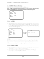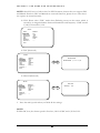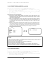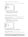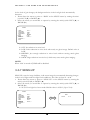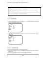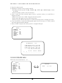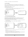
1
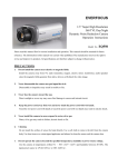
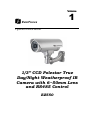
Volume
1
EverFocus
Operation Instruction
1/3” CCD Polestar True
Day/Night Weatherproof IR
Camera with 6~50mm Lens
and RS485 Control
EZ550
EVERFOCUS ELECTRONICS CORPORATION
P/N: MZ55G00200_Ver. B
Operation Instruction
© 2008 EverFocus Electronics Corp
Please read this manual first for correct installation and operation. This manual should be retained
for future reference. The information in this manual was current when published. The
manufacturer reserves the right to revise and improve its products. All specifications are therefore
subject to change without notice.
All rights reserved. No part of the contents of this manual may be reproduced or transmitted in any
form or by any means without written permission of the EverFocus Electronics Corporation.
2
Precautions
1. Do not place any object on top of the cover.
2. Be careful when handling the camera, do not drop it or subject it to strong shock or
vibration to prevent any damages to it. Do not disassemble it or place it on an unstable
base.
3. Install the camera away from TV, radio transmitter, magnet, electric motor, transformer,
audio speakers because the magnetic fields generate from above devices will distort the
video image.
4. Install the camera away from stoves, or other heat generating devices as the high
temperature could cause deformation, discoloration or other damages of the camera. Install
the camera at where the temperature range will stay between -40°C to 50°C (-40°F to
122°F).
5. Never aim the camera at the sun or other extremely bright objects whether it is in use or
not.
6. Do not touch the surface of CCD sensor by hand directly. Use a soft cloth to remove the
dirt from the camera body. Use lens tissue or a cotton tipped applicator and ethanol to
clean the CCD sensor and the camera lens. When the camera is not in use, put the cover
cap on the lens mount.
7. All warnings on the products and in the operating instructions should be adhered to.
8. Do not use attachments not recommended by the appliance manufacturer as they may
cause hazards.
9. Do not allow anything to rest on the power cord. Do not locate this appliance where the
cord will be abused by persons walking on it.
10. Do not overload wall outlets and extension cords as this can result in fire or electric shock.
11. Never push objects of any kind into his appliance through cabinet slots as they may touch
dangerous voltage points or short out parts that could result in fire or electric shock.
12. Refer all work related to the installation of this product to qualified service personnel or
system installers.
3
Federal Communication Commission Interference
Statement
This equipment has been tested and found to comply with the limits for a Class B digital device,
pursuant to Part 15 of the FCC Rules. These limits are designed to provide reasonable
protection against harmful interference in a residential installation. This equipment generates,
uses and can radiate radio frequency energy and, if not installed and used in accordance with the
instructions, may cause harmful interference to radio communications. However, there is no
guarantee that interference will not occur in a particular installation. If this equipment does
cause harmful interference to radio or television reception, which can be determined by turning
the equipment off and on, the user is encouraged to try to correct the interference by one of the
following measures:
Reorient or relocate the receiving antenna.
Increase the separation between the equipment and receiver.
Connect the equipment into an outlet on a circuit different from that to which the
receiver is connected.
Consult the dealer or an experienced radio/TV technician for help.
FCC Caution: Any changes or modifications not expressly approved by the party responsible
for compliance could void the user's authority to operate this equipment.
This device complies with Part 15 of the FCC Rules. Operation is subject to the following two
conditions: (1) This device may not cause harmful interference, and (2) this device must accept
any interference received, including interference that may cause undesired operation.
4
Table of Contents
1.1 Features ....................................................................................................................................... 1
1.2 Accessory Parts List .................................................................................................................... 2
1.3 Specifications............................................................................................................................... 3
1.4 Dimensions ................................................................................................................................... 4
1.5 Camera Component Description .................................................................................................. 6
1.6 Back Panel Layout ....................................................................................................................... 7
1.7 Related Products .......................................................................................................................... 8
2.1 Wiring and Mounting ................................................................................................................... 13
2.2 Adjusting Camera Position ......................................................................................................... 18
2.3 Adjusting Lens ............................................................................................................................ 19
2.3.1 Lens Setting .................................................................................................................... 19
2.4 Keyboard Connection (Optional) ................................................................................................ 20
3.1 Control Key General Operation Guide........................................................................................ 21
3.2 RS485 ID & Baud Rate Setting ................................................................................................... 23
3.3 OSD Menu Setup ......................................................................................................................... 26
3.3.1 LENS ................................................................................................................................ 26
3.3.2 SHUTTER ........................................................................................................................ 26
3.3.3 WHITE BALANCE control ................................................................................................. 28
3.3.4 BACKLIGHT ..................................................................................................................... 28
3.3.5 AGC (Auto Gain Control) .................................................................................................. 29
3.3.6 DNR (Dynamic Noise Reduction) ..................................................................................... 29
3.3.7 SENS-UP .......................................................................................................................... 30
3.3.8 SPECIAL ........................................................................................................................... 31
3.3.8.1 CAMERA ID ........................................................................................................... 31
3.3.8.2 COLOR ADJ ........................................................................................................... 32
3.3.8.3 SYNC ..................................................................................................................... 33
3.3.8.4 MOTION DETECTION ............................................................................................ 33
3.3.8.5 PRIVACY ............................................................................................................... 35
3.3.8.6 MIRROR ................................................................................................................. 37
3.3.8.7 SHARPNESS .......................................................................................................... 37
3.3.8.8 RESET ................................................................................................................... 38
3.3.8.9 RETURN ................................................................................................................ 38
3.3.9 EXIT ................................................................................................................................. 38
4.1 Key Features with Keyboard...................................................................................................... 40
4.2 OSD Menu Setting by Keyboard ................................................................................................. 40
4.3 Lens Adjustment by Keyboard ................................................................................................... 41
5
C H A P T E R 2 I N S T A L L A T I O N
C H A P T E R 1 P R O D U C T O V E R V I E W
Chapter
1
Product Overview
EZ550 camera is a true day/night, long range IR bullet style color camera. With Polestar
sens-up 128x, it offers super sensitivity as 0.002 lux and can capture picture in the
darkness. Engineered with the advanced new generation 16bit DSP, EZ550 has powerful
processing capability to perform super high resolutions. Designed with 3 Axis bracket, you
can position camera at any view angle you like. With built-in DNR (Dynamic Noise
Reduction), the EZ550 camera provides crystal clear images in low light conditions and
70% of substantial disk-saving storage. This bullet style camera supports RS485 remote
control and has an external controller for 6~50mm auto Iris lens and OSD setting.
1.1 Features
•
1/3” SONY Super HAD CCD with super high resolution
•
Sens-up 128x
•
Built-in motor controller for 6~50mm auto Iris lens (zoom and focus)
•
3 Axis Bracket
•
True Day/Night feature with IR Cut Filter Removable
•
OSD setting menu and RS485 remote control
•
IR distance up to 50 meters (about 164 ft.) and Vari-Frequency IR control
•
Utilizes the advanced 16-bit Digital Signal Processor (DSP) for crystal clear images
•
Built-in DNR (Dynamic Noise Reduction) for noise reduction and 70% saving of disk
storage
•
Built-in heater for applications in low temperature environment
•
Tamper-proof: cable wires are placed inside the bracket to prevent intentional destruction
•
IP66 weatherproof and vandal proof
1
C H A P T E R
C H A P T E R
2
1
I N S T A L L A T I O N
P R O D U C T O V E R V I E W
1.2 Accessory Parts List
Please be careful when you unpack the box due to the electronics devices inside. Check
and make sure that you have all the items listed below inside the original box:
•
Camera Unit x 1
•
Waterproof conduit x 1 (connected to the camera bottom)
•
Bracket x 1
•
Operation Manual x 1
•
Mounting kit includes:
-Long Screws x 4 (for mounting bracket)
-Short Screws x 4 (for connecting camera body to bracket)
-Expanding Screws x 4
-Hex key x 1 (for adjusting bracket)
-Hexagon wrench x 1 (for adjusting sunshield)
Please Note: If an item appears to have been damaged in shipment, replace it properly in its
carton and notify the shipper. If any items are missing, notify your EverFocus Electronics Corp.
Sales Representative or Customer Service. The shipping carton is the safest container in which
the unit may be transported. Save it for possible future use.
2
C H A P T E R 2 I N S T A L L A T I O N
C H A P T E R 1 P R O D U C T O V E R V I E W
1.3 Specifications
Items
Pickup Device
Picture Elements
Video Format
Scanning System
Horizontal Resolution
Video Output
Lens Type
Sensitivity
Gamma Correction
S/N Ratio
Electronic Shutter
True Day/Night
Auto White Balance
Black Light Comp.
Auto Gain Control
Digital Noise Reduction
Sens-Up
Sync. Mode
IR LED Lifespan
Weatherproof
Vandal Resistant
Heater
Power Source
Power Consumption
Dimensions
Operating Temperature
Weight
IR Distance
IR Wavelength
Certifications
Parameter
1/3” SONY Super HAD CCD
768 x 494 (NTSC) ; 752 x 582 (PAL)
NTSC or PAL
NTSC: 525 TV lines, 60 fields/sec
PAL: 625 TV lines, 50 fields/sec
560 TVL
BNC 1.0Vp-p / 75 ohm
Vari-focal f=6~50mm
0.002 Lux/F=1.2 (IR Off, SENS-UP 128x)
0 Lux (IR On)
0.45
50 dB
1/50 (1/60) ~1/100,000
Yes
ATW; AWC; Manual
Yes,(OFF; Low ; Mid ; Hi)
Yes,(OFF ; Low ; Mid ; Hi)
Yes,(OFF ; Low ; Mid ; Hi)
128x, Auto
Internal; Line lock
20,000 hours
IP66
Yes
Yes, built-in
2 types:100VAC~240VAC;24VAC
100VAC~240VAC: 18W max.
24VAC: 20W max.
115mm(W) x 115mm(H) x 275mm(D) ;
4.5"(W) x 4.5" (H) x 10.8"(D)
-40°C ~ +50°C ; -40℉ ~ 122℉
(20%~80% Humidity)
2.5 kg ; 5.5 lbs (with bracket)
50M / 164 feet
850nm
FCC, CE
3
C H A P T E R 2 I N S T A L L A T I O N
C H A P T E R 1 P R O D U C T O V E R V I E W
1.4 Dimensions
Drilling Dimension of holes to holes
45mm/1.8”
80mm/3.2”
Dimension of Bracket
220.5mm/8.68”
84mm/3.31”
106.5mm/4.19
112.7mm/4.44
199mm/7.83”
4
C H A P T E R
2
I N S T A L L A T I O N
Dimension of whole camera with bracket
275mm/10.8”
107.5mm/4.3”
243.5mm/9.74”
357mm/14”
5
C H A P T E R
C H A P T E R
2
1
I N S T A L L A T I O N
P R O D U C T O V E R V I E W
1.5 Camera Component Description
Sun shield
Fixing screw for sunshield
Bracket
Power connector
RS485 terminal
Video output
Control key selection switch
Control key
EZ550 Component description
6
C H A P T E R
C H A P T E R
2
1
I N S T A L L A T I O N
P R O D U C T O V E R V I E W
1.6 Back Panel Layout
24VAC model (for 24VAC
Power Only)
2
110V~240VAC model (for
110V ~240V Power only)
2
1
1
3
4
3
5
5
6
6
7
7
1. Video Output Connector
Connect the video output of the camera to a color monitor or other video devices through
a 75 Ohm type coaxial cable with BNC female connector at backside of the camera.
2. Power Input Terminal
Connect the appropriate power to each model. N/L is used to connect to power in. PE is
a ground pin.
3. RS-485 communication and External IR power control pin
485-
485+
GND
12VDC
PIN definition:
a. TXD (RS485 +): for keyboard controlling.
b. RXD (RS485-): for keyboard controlling.
4. Power for IR illuminator
Referring to above figure, pin 12VDC and GND are defined as below:
a. GND: Ground
b. 12VDC: provide power source for IR illuminator (IR illuminator is optional).
7
4
C H A P T E R
2
I N S T A L L A T I O N
5. Control key selection switch
Switch to OSD to control OSD menu by using the control key or switch to LENS to
adjust zooming and focus (please see “2.3.1 Lens setting” and “3. OSD Menu &
Configuration” for details).
Note: when it is connected to RS485 for keyboard control, please switch to OSD,
otherwise it cannot be controlled remotely.
6. Control key
For setting Lens & OSD menu.
7. Cable clips
Used to fix power cable and RS485 cable.
1.7 Related Products
In addition, you may order the following EverFocus products which are recommended for use
with the camera to achieve the best performance:
•
EverFocus control keyboard (EKB500)
•
IR Illuminator and bracket
8
C H A P T E R
2
I N S T A L L A T I O N
Chapter
2
Installation
This chapter will describe, in general terms, how to install the EZ550 camera.
STEPS:
1. Wire and mount the camera. See 2.1
2. Adjust the camera position. See 2.2
3. Adjust Lens. See 2.3
4. Connect to Keyboard (Optional) See 2.4
Warning
•
•
To prevent electrical shock, turn off the electrical power before making electrical
connections.
Do not expose the appliance to water or moisture, nor try to operate it in wet
areas.
2.1 Wiring and Mounting
1. Wire coaxial cable, power cable and RS485 cable through the bracket.
Note: 1. Please use RG59/5C2V coaxial cable without connector
2. Use RS485 cable only if you need to control the camera by a keyboard.
Coaxial cable
Power cable
RS485 cable
13
C H A P T E R
2
I N S T A L L A T I O N
2. Fix the bracket to wall by using 4 screws.
Coaxial cable
Power cable
RS485 cable
3. Open camera’s back cover: Loose the 2 screws from the back panel cover, then open the
back cover.
Screws for back panel
14
C H A P T E R
4.
2
I N S T A L L A T I O N
Take off the cap of waterproof conduit which is at the camera bottom.
Power cable (Φ10.3mm)
Coaxial cable
(Φ6mm)
RS485
(Φ5mm)
Note: 1. the holes of waterproof conduit were plugged, please remove the plug when
you need to use it for connection.
5. Take coaxial cable, power cable and RS485 cable to pass through waterproof conduit,
place them into camera housing.
Note: Do not connect BNC connector to coaxial cable until coaxial cable has passed
through camera housing otherwise your cable might not pass the housing.
15
C H A P T E R
2
I N S T A L L A T I O N
Coaxial cable
Power cable
RS485 cable
Note: 1. Power cable’s diameter must be less than 10 mm
2. Only use RG59/5C2V for Video cable
3. RS485 cable must be less then 5 mm
6. Close the waterproof cap and fix waterproof conduit to the base of camera firmly.
16
C H A P T E R
7.
2
I N S T A L L A T I O N
Fix the camera body to bracket by using the 4 shorter screws.
8. Connect RG59 coaxial cable with BNC connector.
9. Unscrew both cable clips, wire power cable and RS485 cable through the cable clips.
Then, screw the cable clips to rear panel.
a. Connecting Power-24VAC model: connect 24VAC power on N and L
100VAC~240VAC Model: Connect PE, N and L.
*Warning*
•
•
•
To prevent electrical shock, turn off the electrical power before making electrical
connections.
Do not connect high voltage power to the camera. It may damage the camera.
Do not short circuit the power leads and expose the wire when connecting the
power supply to the camera.
b. Connect Video- Make sure connecter is firmly connected.
c. Connecting RS485 (optional): Connect RS585 cable to 485+ and 485-. Please use
screw driver to lose and tight the screw on the RS485 terminal pin when you do
connection.
Power cable
RS485 cable
Coaxial cable
Cable Clips
Cable Clips
17
C H A P T E R
2
I N S T A L L A T I O N
10. Close the back cover and screw the 2 screws firmly. Now, you are done with the
installation.
NOTE: Before you close the cover, please make sure control key is attached firmly and
wire doesn’t stuck.
Screws for back panel
2.2 Adjusting Camera Position
Adjust camera’s angle vertically or horizontally by using hex key included in package.
Loose this screw to make
angle adjustment vertically
18
C H A P T E R
2
I N S T A L L A T I O N
Loose this screw to make angle
adjustment horizontally
2.3 Adjusting Lens
Open camera’s base, a control key is attached at inner side of the base. Detach the control
key and use this key for OSD or Lens setting.
UP
2.3.1 Lens Setting
Please turn the control key selection switch at the back panel to “Lens”.(
control key to do lens setting.
19
). Use the
C H A P T E R
2
I N S T A L L A T I O N
UP
Mini-Joystick
The Cursors & the mini-joystick
Turn the mini-joystick Up (c) or Down (d) to adjust zoom in / zoom out,
Turn the mini-joystick Left (e) or Right (f) to adjust focus.
2.4 Keyboard Connection (Optional)
Please refer to Chapter 4 for more details of Keyboard control.
1.
2.
Connect the cable from keyboard’s RS485 port to camera’s RS485 port. (Keyboard is
an optional accessory). RS485 connecting accessories are included in Everfocus
Keyboard package.
Connect the cable from video output jack of the camera to monitor’s input jack.
20
C H A P T E R
3.
4.
5.
2
I N S T A L L A T I O N
EZ550 recognizes EVF-1, EVF-2 and Pelco-D protocols automatically. (No setting is
required)
The camera default RS485_ID is 99. BAUD_RATE is 9600. Make sure the key board
camera ID and Baud rate match. For optional changing camera ID and baud rate on
camera, please refer to 3.2.
For keyboard setting and operation, please see chapter 4 .
21
C H A P T E R
3
O S D
M E N U
A N D
C O N F I G U R A T I O N
Chapter
3
OSD Menu & Configuration
This chapter introduces how to configure the camera OSD menu.
3.1 Control Key General Operation Guide
Please turn the control key selection switch at the back panel to “OSD” ”(
Use the control key to do OSD menu setting.
).
UP
Mini-Joystick
The Cursors & the mini-joystick
I.
Bring Up the General OSD Menu
Simply press the mini-joystick to bring up the general OSD menu.
II. Bring up the RS485 Setting Menu
Press the mini-joystick and hold for 5 seconds to bring up the RS485 setting menu.
III. Navigate among the OSD Menu Items
Turn the mini-joystick up (c) or down (d) to move the cursor up or down.
IV. Change Modes or Setting Parameters
Turn the mini-joystick left (e) or right (f) to adjust the mode or parameter of
settings.
V. Switch to Sub-menu Screens
21
C H A P T E R
3
O S D
M E N U
A N D
C O N F I G U R A T I O N
When the item with sub-menu is selected, press the mini-joystick to switch to the submenu for further settings. Please refer to the diagram below.
SETUP
LENS
> LENS
DC <┘
SHUTTER
___
WHITE BAL.
ATW
BACKLIGHT
OFF
AGC
MainMIDDLE
Menu
DNR
LOW
SENS-UP
AUTO <┘
SPECIAL <┘
EXIT
NOTE:
For those selected items with “
settings.
LEVEL |+++++++++| 25
Sub-Menu
s Menu
” sign in the end, they have the sub-menu for further
VI. Return to Previous Page
Press the mini-joystick to return to previous page.
VII. Close the Host Menu Screen
To close the menu screen, navigate to the “EXIT” item and press the mini-joystick.
22
C H A P T E R
3
O S D
M E N U
A N D
C O N F I G U R A T I O N
3.2 RS485 ID & Baud Rate Setting
Note: This section is optional preserved for the people that want to change camera ID and
baud rate. In most situations, we suggest you can just use Camera ID-99 and Baud Rate-9600,
Protocol-Pelco D on keyboard, then it would work.
I. Please turn the control key selection switch at back panel to “OSD”(
).
II. Press the mini-joystick for 4 seconds until you see the following menu.
A
N
a
n
─
B
O
b
o
·
C
P
c
p
D
Q
d
q
0
E
R
e
r
1
F
S
f
s
2
G
T
g
t
3
H
U
h
u
4
I
V
i
v
5
J
W
j
w
6
K
X
k
x
7
L
Y
l
y
8
M
Z
m
z
9
C L R
P O S
E N D
←
→
F I R M WA R E _ V E R _ _ _
III. Turn the mini-joystick up (c) or down (d) to adjust setting, press mini-joystick to go next
selection.
IV. Please wait 3 seconds after setting any item, it will automatically switch to next setting item.
V. Camera setting order:
a. Firmware version. VER_xxx- shows the current firmware version.
23
C H A P T E R
3
O S D
M E N U
A
N
a
n
─
A N D
B
O
b
o
·
C
P
c
p
C O N F I G U R A T I O N
D
Q
d
q
0
E
R
e
r
1
F
S
f
s
2
G
T
g
t
3
H
U
h
u
4
I
V
i
v
5
J
W
j
w
6
K
X
k
x
7
L
Y
l
y
8
M
Z
m
z
9
C L R
P O S
E N D
←
→
F I R M WA R E _ V E R _ _ _
b. RS485_ID- adjustable 01~99. Default value is 99. Move joystick RIGHT and LEFT to adjust
it. RS485 ID of EZ550 has to be the same as Keyboard’s CAM ID.
A
N
a
n
─
B
O
b
o
·
C
P
c
p
D
Q
d
q
0
E
R
e
r
1
F
S
f
s
2
G
T
g
t
3
H
U
h
u
4
I
V
i
v
5
J
W
j
w
6
K
X
k
x
7
L
Y
l
y
8
M
Z
m
z
9
C L R
P O S
E N D
←
→
R S 4 8 5 I D _ 9 9 _ _ _ _ _
c. BAUD_RATE-adjustable 9600, 4800, 2400 and 1200. Default value is 9600. Move joystick
RIGHT and LEFT to adjust it. Baud rate of EZ550 has to be the same as Keyboard’s baud
rate.
A
N
a
n
─
B
O
b
o
·
C
P
c
p
D
Q
d
q
0
E
R
e
r
1
F
S
f
s
2
G
T
g
t
3
H
U
h
u
4
I
V
i
v
5
J
W
j
w
6
K
X
k
x
7
L
Y
l
y
8
M
Z
m
z
9
C L R
P O S
E N D
←
→
B A U D _ R A T E _ 9 6 0 0 _
24
C H A P T E R
3
O S D
M E N U
A N D
C O N F I G U R A T I O N
d. DATA STORED- Confirm with you that the last 3 settings you have made will be saved.
A
N
a
n
─
B
O
b
o
·
C
P
c
p
D
Q
d
q
0
E
R
e
r
1
F
S
f
s
2
G
T
g
t
3
H
U
h
u
4
I
V
i
v
5
J
W
j
w
6
K
X
k
x
7
L
Y
l
y
8
M
Z
m
z
9
C L R
P O S
E N D
←
→
D A T A _ S T O R E D _ _ _ _
e. ENTER_SET_MENU- press the mini-joystick to enter OSD menu setting.
A
N
a
n
─
B
O
b
o
·
C
P
c
p
D
Q
d
q
0
E
R
e
r
1
F
S
f
s
2
G
T
g
t
3
H
U
h
u
4
I
V
i
v
5
J
W
j
w
6
K
X
k
x
7
L
Y
l
y
8
M
Z
m
z
9
C L R
P O S
E N D
←
→
E N T E R _ S E T _ M E N U _
Note: For Camera Protocol, EZ550 recognizes EVF-1, EVF-2 and Pelco-D protocols
automatically. (No setting is required)
After setting, it will show an OSD menu, to save setting, go to exit menu and press minijoystick.
Note: Camera ID and Baud rate setting can only be performed locally, NOT from
Keyboard.
25
C H A P T E R
3
O S D
M E N U
A N D
C O N F I G U R A T I O N
3.3 OSD Menu Setup
Please make sure control key selection switch is at OSD position.
Note: Unlike setting Camera ID that requires you to press 3 seconds, OSD menu only
requires one click (less than 1 second) and you should see the following menu.
SETUP
> LENS
SHUTTER
WHITE BAL.
BACKLIGHT
AGC
DNR
SENS-UP
SPECIAL <┘
EXIT
DC <┘
___
ATW
OFF
MIDDLE
LOW
AUTO <┘
3.3.1 LENS
1. When the SETUP menu is displayed on the screen, please direct the arrow to point to
“LENS” by turning the mini-joystick UP (c) or DOWN (d). Press the mini-joystick
to adjust IRIS level (the higher is brighter). In most cases, you don’t need to adjust this,
since Lens is Auto Iris supported.
SETUP
> LENS
SHUTTER
WHITE BAL.
BACKLIGHT
AGC
DNR
SENS-UP
SPECIAL <┘
EXIT
DC <┘
___
ATW
OFF
MIDDLE
LOW
AUTO <┘
LENS
LEVEL
|+++++++++| 25
NOTE:
Since DC lens is a built-in lens for EZ550 camera, it does not support Manual lens, please
do not select lens as Manual mode, it disables sens-up and may cause malfunction of lens.
2. Please press the mini-joystick for saving setting and return to the previous menu.
3.3.2 SHUTTER
1. When the SETUP menu is displayed on the screen, please direct the arrow to point to
“SHUTTER” by turning the mini-joystick DOWN (d).
2. Select the shutter mode by turning the mini-joystick LEFT (e) or RIGHT (f).
Three modes are available. FLK, ESC and Manual.
26
C H A P T E R
3
O S D
M E N U
A N D
C O N F I G U R A T I O N
NOTE: Since DC lens is a built-in lens for EZ550 camera, shutter does not support ESC
and Manual functions. ESC and Manual are reserved functions, please do not select these
two options in normal situation.
Ö FLK: Please select “FLK” mode when flickering occurs on the screen, which is
caused by an irregular balance between illumination and frequency. NTSC model:
1/100, PAL model: 1/120.
SETUP
LENS
> SHUTTER
WHITE BAL.
BACKLIGHT
AGC
DNR
SENS-UP
SPECIAL <┘
EXIT
MANUAL
FLK
ATW
OFF
MIDDLE
LOW
___
Ö ESC (Reserved).
SETUP
LENS
> SHUTTER
WHITE BAL.
BACKLIGHT
AGC
DNR
SENS-UP
SPECIAL <┘
EXIT
BRIGHTNESS
MANUAL
ESC <┘
ATW
OFF
MIDDLE
LOW
AUTO <┘
BRIGHTNESS
|+++++++++| 25
Ö Manual (Reserved).
SETUP
LENS
> SHUTTER
WHITE BAL.
BACKLIGHT
AGC
DNR
SENS-UP
SPECIAL <┘
EXIT
SHUTTER
MANUAL
MANUAL <┘
ATW
OFF
MIDDLE
LOW
___
> MANUAL
1/50
3. Press the mini-joystick when you finish all the settings.
NOTE:
1 With DC lens, the shutter speed is fixed as 1/60 for NTSC and 1/50 for PAL.
○
27
C H A P T E R
3
O S D
M E N U
A N D
C O N F I G U R A T I O N
3.3.3 WHITE BALANCE control
The screen color can be adjusted by using the WHITE BALANCE function.
1. Please direct the arrow to point to “WHITE BAL” on the SETUP menu by turning
the mini-joystick UP (c) or DOWN (d).
2. Please select the mode you would like to operate by turning the mini- joystick LEFT
(e) or RIGHT (f).
Please select one of the 3 modes below:
Ö ATW (Auto Tracking White Balance): This mode can be used within the color
temperature range from 2,500°K to 8,300°K (eg, fluorescent light, outdoor, sodium
vapor lamp or inside tunnels).
Ö AWC (Auto White Balance Control): Press mini-joystick while the camera is directed
at a piece of white paper to get the optimum state under the present illumination. If
the environment and the light source are changed, you need to adjust the white
balance again.
Ö MANUAL: The manual adjustment mode enables a more precise adjustment. Please
select ATW or AWC first. Then change to manual adjustment mode and press minijoystick. Set the suitable color temperature, and increase or decrease the red and blue
color values at the same time while checking the color changes of the object.
SETUP
LENS
SHUTTER
> WHITE BAL.
BACKLIGHT
AGC
DNR
SENS-UP
SPECIAL <┘
EXIT
WHITE BAL.
DC <┘
___
MANUAL <┘
OFF
MIDDLE
LOW
AUTO <┘
RED
BLUE
|+++++++++| 32
|+++++++++| 39
NOTE:
Under the following conditions, the WHITE BALANCE function may not operate well. In
such cases, please select the AWC mode.
1 When the object’s surroundings have a high color temperature.
○
2 When the object’s surroundings are dark.
○
3 If the camera faces a fluorescent light directly or is installed in a place where the
○
illumination changes constantly, the WHITE BALANCE function may become unstable.
3.3.4 BACKLIGHT
Even there is a massive backlight behind the object, bright images of the background and
the object can still be obtained by using the BACKLIGHT function.
1. Please direct the arrow to point to “BACKLIGHT” on the SETUP menu by turning
the mini-joystick UP (c) or DOWN (d).
28
C H A P T E R
3
O S D
M E N U
A N D
C O N F I G U R A T I O N
2. Select the mode you would like to operate by turning the mini-joystick LEFT (e) or
RIGHT (f).
SETUP
LENS
SHUTTER
WHITE BAL.
> BACKLIGHT
AGC
DNR
SENS-UP
SPECIAL <┘
EXIT
Ö
Ö
Ö
Ö
DC <┘
___
ATW
OFF
MIDDLE
LOW
AUTO <┘
HIGH: The gain increases from 0dB up to 42dB.
MIDDLE: The gain increases from 0dB up to 30dB.
LOW: The gain increases from 0dB up to 18dB.
OFF: BACKLIGHT function does not operate.
3.3.5 AGC (Auto Gain Control)
1. Please direct the arrow to point to “AGC” on the SETUP menu by turning the minijoystick UP (c) or DOWN (d).
2. Select the mode you would like to operate by turning the mini-joystick LEFT (e) or
RIGHT (f). The more the level of gain increases, the brighter the screen and the level
of noise increases as well.
Ö HIGH: The gain increases from 6dB up to 42dB.
Ö MIDDLE: The gain increases from 6dB up to 30dB.
Ö LOW: The gain increases from 6dB up to 18dB.
Ö OFF: The gain is fixed at 6dB.
SETUP
LENS
SHUTTER
WHITE BAL.
BACKLIGHT
> AGC
DNR
SENS-UP
SPECIAL <┘
EXIT
DC <┘
___
ATW
OFF
MIDDLE
LOW
AUTO <┘
3.3.6 DNR (Dynamic Noise Reduction)
Dynamic Noise Reduction in video images has the following effects.
1. Images are brighter and sharper.
2. When the level of noise is reduced, the performance of a camera can apparently be
improved.
3. When it is recorded digitally, reduced noise can reduce image file size.
29
C H A P T E R
3
O S D
M E N U
A N D
C O N F I G U R A T I O N
As the level of gain changes, the background noise in the low light level automatically
decreases.
1. Please direct the arrow to point to “DNR” on the SETUP menu by turning the minijoystick UP (c) or DOWN (d).
2. Select the mode you would like to operate by turning the mini-joystick LEFT (e) or
RIGHT (f).
SETUP
LENS
SHUTTER
WHITE BAL.
BACKLIGHT
AGC
> DNR
SENS-UP
SPECIAL <┘
EXIT
DC <┘
___
ATW
OFF
MIDDLE
LOW
AUTO <┘
Ö OFF: No reduction in noise level.
Ö LOW: Little reduction in noise level with nearly no ghost image. Default value is
LOW.
Ö MIDDLE: Just enough reduction in noise levels without causing much ghost
imaging.
Ö HIGH: Huge reduction in noise level, which may cause much ghost imaging.
NOTE:
When AGC is turned off, DNR will be disabled.
3.3.7 SENS-UP
SENS UP is used to keep a brilliant, vivid screen image by automatically detecting changes
in the level of light under low light level conditions. The value is from x2 ~x128.
1. Please direct the arrow to point to “SENS UP” on the SETUP menu by turning the
mini-joystick UP (c) or DOWN (d).
2. Select the mode you would like to operate by turning the mini-joystick LEFT (e) or
RIGHT (f).
Ö AUTO: Low light level auto mode. Default value is AUTO (Up to X 10).
SETUP
LENS
SHUTTER
WHITE BAL.
BACKLIGHT
AGC
DNR
> SENS-UP
SPECIAL <┘
EXIT
LIMIT
DC <┘
___
ATW
OFF
MIDDLE
LOW
AUTO <┘
> AUTO
Ö OFF: The function is disabled.
30
X 10
C H A P T E R
3
O S D
M E N U
A N D
C O N F I G U R A T I O N
3. Press the mini-joystick when you finish all the settings.
NOTE:
1 The maximum storage magnification in low light level movement situations can be
○
adjusted by pressing the mini-joystick in “AUTO” mode.
2 The screen becomes brighter when the magnification increases; yet the after image
○
increases as well.
3 Please be noted that spots and noise may appear if storage magnification increases when
○
SENS-UP is operating. This is a normal phenomenon.
3.3.8 SPECIAL
1. Please direct the arrow to point to “SPECIAL” on the SETUP menu by turning the
mini-joystick UP (c) or DOWN (d).
SETUP
LENS
SHUTTER
WHITE BAL.
BACKLIGHT
AGC
DNR
SENS-UP
> SPECIAL <┘
EXIT
DC <┘
___
ATW
OFF
MIDDLE
LOW
AUTO <┘
2. Select the mode you would like to operate by turning the mini-joystick LEFT (e) or
RIGHT (f).
SPECIAL
> CAMERA ID
OFF
COLOR ADJ. <┘
SYNC.
INT
MOTIION DET OFF
PRIVACY
OFF
MIRROR
OFF
SHARPNESS
ON <┘
RESET
RETURN <┘
3.3.8.1 CAMERA ID
Input the camera ID, and it will be appeared on the monitor.
1) Please direct the arrow to point to “CAMERA” by turning the mini-joystick UP (c) or
DOWN (d).
2) Select “ON” by turning the mini-joystick LEFT (e) or RIGHT (f).
31
C H A P T E R
3
O S D
M E N U
A N D
C O N F I G U R A T I O N
3) Press the mini-joystick.
4) Maximum 15 letters can be used for the ID.
¾ Turning the mini-joystick UP (c), DOWN (d), LEFT (e) or RIGHT (f) to select
the letters.
¾ Press the mini-joystick to lock in the letters.
5) Once a name has been selected, please choose a position where you would like to
display the name.
¾ Move the cursor onto “POS” and press the mini-joystick.
¾ The name will appear at the top left hand corner.
¾ Please use the 4 directional buttons to find the desired position to display the name.
6) If you would like to cancel the ID inputted, please move the cursor to “CLR”, and all
the letters inputted will be deleted.
7) Select “END” and press the mini-joystick to complete ID input.
SPECIAL
> CAMERA ID
ON
COLOR ADJ. <┘
SYNC.
INT
MOTIION DET OFF
PRIVACY
OFF
MIRROR
OFF
SHARPNESS
ON <┘
RESET
RETURN <┘
C A M E R A
A
N
a
n
─
B
O
b
o
·
C
P
c
p
D
Q
d
q
0
E
R
e
r
1
F
S
f
s
2
G
T
g
t
3
I D
H
U
h
u
4
I
V
i
v
5
J
W
j
w
6
K
X
k
x
7
L
Y
l
y
8
M
Z
m
z
9
C L R
P O S
E N D
←
→
_ _ _ _ _ _ _ _ _ _ _ _ _ _ _
3.3.8.2 COLOR ADJ
Adjust the Color Gain from 0 ~ 15
SPECIAL
COLOR GAIN.
CAMERA ID
OFF
> COLOR ADJ. <┘
SYNC.
INT
MOTIION DET OFF
PRIVACY
OFF
MIRROR
OFF
SHARPNESS
ON <┘
RESET
RETURN <┘
> LEVEL
32
|++++++++| 8
C H A P T E R
3
O S D
M E N U
A N D
C O N F I G U R A T I O N
3.3.8.3 SYNC
There are two SYNCHRONIZATION modes: INTERNAL and EXTERNAL LINELOCK. In LINE-LOCK mode, without a synchronous generator, it synchronizes the
video signal between cameras. The Line-Lock synchronization is only used in the places of
60Hz (NTSC models) or 50Hz (PAL models).
-INT: Internal synchronization
-LL: External line-lock synchronization
=> If you choose “LL”, you can adjust the phase your wish to set. Then press the minijoystick. You can adjust the phase you wish to set from 0 to 359.
SPECIAL
CAMERA ID
OFF
COLOR ADJ. <┘
> SYNC.
LL <┘
MOTIION DET OFF
PRIVACY
OFF
MIRROR
OFF
SHARPNESS ON <┘
RESET
RETURN <┘
SYNC
> PHASE
|++++++++| 0
3.3.8.4 MOTION DETECTION
EZ550 enables you to observe movements of objects in 4 different places on the screen,
the message “MOTION DETECTED” appears on the screen when movement is
detected; therefore this helps to improve supervision efficiency. The camera detects an
object’s movement by sensing discrepancy of outline.
1) Please direct the arrow to point to “MOTION DET” by turning the mini-joystick UP
(c) or DOWN (d).
2) Select “ON” by turning the mini-joystick LEFT (e) or RIGHT (f).
3) Press the mini-joystick.
SPECIAL
MOTION DETECTION
CAMERA ID
OFF
COLOR ADJ. <┘
SYNC.
INT
> MOTIION DET
ON <┘
PRIVACY
OFF
MIRROR
OFF
SHARPNESS
ON <┘
RESET
RETURN <┘
> AEREA SEL
AREA STATE
TOP
DOWN
LEFT
RIGHT
AREA1
ON
|+++++++++| 10
|+++++++++| 25
|+++++++++| 20
|+++++++++| 40
Press SET to return
z Please select the area you would like to detect from the 4 areas in AREA SEL
mode.
z Please select ON mode for the chosen area.
z Please turn mini-joystick UP (c) or DOWN (d) to move between TOP,
DOWN, LEFT and RIGHT for adjusting the size of the area.
z Please turn mini-joystick LEFT (e) or RIGHT (f) to adjust the value for size of
the area.
33
C H A P T E R
3
O S D
M E N U
A N D
AREA1
AREA2
AREA3
AREA4
C O N F I G U R A T I O N
z Additionally, it is possible to change the position of the area. Please refer to the
following example for detailed steps on moving AREA1 to center.
1. The original position of AREA1 was TOP: 10, DOWN: 25, LEFT: 20 and RIGHT:
40.
AREA1
2. Increase DOWN scale value by 20. AREA1 position after change is: TOP: 10,
DOWN: 45, LEFT: 20 and RIGHT: 40.
AREA1
3. Increase TOP scale value by 20. AREA1 position after change is: TOP: 30, DOWN:
45, LEFT: 20 and RIGHT: 40.
AREA1
34
C H A P T E R
3
O S D
M E N U
A N D
C O N F I G U R A T I O N
4. Increase RIGHT scale value by 20. AREA1 position after change is: TOP: 30,
DOWN: 45, LEFT: 20 and RIGHT: 60.
AREA1
5. Increase LEFT scale value by 20. AREA1 position after change is: TOP: 30, DOWN:
45, LEFT: 40 and RIGHT: 60.
AREA1
z In order to save the changes and complete the setting, press the mini-joystick. This
allows you to return to the previous menu.
3.3.8.5 PRIVACY
This mode covers the areas you do not want to see on the screen.
1)
Please direct the arrow to point to “PRIVACY” by turning the mini-joystick UP
(c) or DOWN (d).
2)
Select “ON” by turning the mini-joystick LEFT (e) or RIGHT (f).
3)
Press the mini-joystick.
SPECIAL
PRIVACY
CAMERA ID
OFF
COLOR ADJ. <┘
SYNC.
INT
MOTIION DET
OFF
> PRIVACY
ON <┘
MIRROR
OFF
SHARPNESS
ON <┘
RESET
RETURN <┘
> AEREA SEL
AREA STATE.
AREA TONE
TOP
DOWN
LEFT
RIGHT
AREA1
OFF
|+++++++++| 80
|++++++++| 10
|+++++++++| 25
|+++++++++| 20
|+++++++++| 40
z Please select the area you would like to cover from the 4 areas in AREA SEL
mode.
z Please select ON mode for the chosen area.
z Please select AREA TONE for cover area color. The smaller the number, the
darker the color.
z Please turn the mini-joystick UP (c) or DOWN (d) to move between TOP,
DOWN, LEFT and RIGHT for adjusting the size of the area to be covered.
35
C H A P T E R
3
O S D
M E N U
A N D
C O N F I G U R A T I O N
z Please turn the mini-joystick LEFT (e) or RIGHT (f) to adjust the value for size
of the area to be covered.
z
AREA1
AREA2
AREA3
AREA4
Additionally, it is possible to change the position of the area to be covered.
Please refer to the following example for detailed steps on moving AREA1 to
center.
1. The original position of AREA1 was TOP: 10, DOWN: 25, LEFT: 20 and RIGHT:
40.
AREA1
2. Increase DOWN scale value by 20. AREA1 position after change is: TOP: 10,
DOWN: 45, LEFT: 20 and RIGHT: 40.
AREA1
3. Increase TOP scale value by 20. AREA1 position after change is: TOP: 30, DOWN:
45, LEFT: 20 and RIGHT: 40.
AREA1
36
C H A P T E R
3
O S D
M E N U
A N D
C O N F I G U R A T I O N
4. Increase RIGHT scale value by 20. AREA1 position after change is: TOP: 30,
DOWN: 45, LEFT: 20 and RIGHT: 60.
AREA1
5. Increase LEFT scale value by 20. AREA1 position after change is: TOP: 30, DOWN:
45, LEFT: 40 and RIGHT: 60.
AREA1
z
In order to save the changes and complete the setting, press the mini-joystick.
This allows you to return to the previous menu.
3.3.8.6 MIRROR
-ON: Sets a horizontal image 180 angel inversion.
-OFF: Disable the inversion.
SPECIAL
CAMERA ID
OFF
COLOR ADJ. <┘
SYNC.
INT
MOTIION DET OFF
PRIVACY
OFF
> MIRROR
OFF
SHARPNESS
ON <┘
RESET
RETURN <┘
3.3.8.7 SHARPNESS
The contour of the video image becomes cleaner and more distinguishing as the level of
SHARPNESS increases. If the level goes up extremely, it may affect the video image and
cause noise.
-ON: Enable the SHARPNESS mode.
37
C H A P T E R
3
O S D
M E N U
A N D
C O N F I G U R A T I O N
-OFF: Disable the SHARPNESS mode.
z Please press the mini-joystick.
z The available range of level is 0~31.
SPECIAL
CAMERA ID
OFF
COLOR ADJ. <┘
SYNC.
INT
MOTIION DET OFF
PRIVACY
OFF
MIRROR
OFF
> SHARPNESS
ON <┘
RESET
RETURN <┘
SHARPNESS
> LEVEL
|+++++++++| 8
3.3.8.8 RESET
Press the mini-joystick on RESET for 3 seconds until it restarts. It will go to factory
default value.
SPECIAL
CAMERA ID
OFF
COLOR ADJ. <┘
SYNC.
INT
MOTIION DET OFF
PRIVACY
OFF
MIRROR
OFF
SHARPNESS
ON <┘
> RESET
RETURN <┘
3.3.8.9 RETURN
Press the mini-joystick on RETURN. It saves all settings in SPECIAL menu and returns to
the Setup menu.
SPECIAL
CAMERA ID
OFF
COLOR ADJ. <┘
SYNC.
INT
MOTIION DET OFF
PRIVACY
OFF
MIRROR
OFF
SHARPNESS
ON <┘
RESET
> RETURN <┘
3.3.9 EXIT
Press the mini-joystick on EXIT after you finish all the settings. It will return to live image.
NOTE:
If you quit the Menu without pressing EXIT, all the settings you previously did will
NOT be saved.
38
C H A P T E R
3
O S D
M E N U
A N D
C O N F I G U R A T I O N
39
C H A P T E R
4
C O N T R O L
F R O M
K E Y B O A R D
Chapter
4
Control from Keyboard
EKB500 (Optional)
Note!
Before being able to control keyboard, make sure Keyboard RS485 camera ID, Baud rate
match the camera. (see COM port setting in EKB500 manual). EZ550 camera ID default
is 99. Baud rate is 9600. Support Protocol EVF-1, EVF-2 and Pelco-D.
4.1 Key Features with Keyboard
1. OSD can be set up from Keyboard.
2. Lens Zoom and Focus can be controlled by keyboard.
4.2 OSD Menu Setting by Keyboard
a.
Press “Menu” to enter SETUP menu.
b. Move the joystick UP (c) and DOWN (d). This allows you to move between
selection items in setup menu.
c. If the item has sub-menu setting (sign
sub-menu.
SETUP
> LENS
SHUTTER
WHITE BAL.
DC <┘
___
ATW
40
), press “Menu” again to display the
C H A P T E R
d.
4
C O N T R O L
F R O M
K E Y B O A R D
Move the joystick RIGHT (f) and LEFT (e) to adjust the mode and parameters
of the selected item.
e. Press “Menu” to leave and goes to previous menu after setting. Move to “exit” and
press “menu” button when you finish all settings.
f. For detail setting and every setup function, Please refer to “3.3. OSD Menu Setup”.
4.3 Lens Adjustment by Keyboard
1. Press Zoom in or Zoom out to adjust zoom or Turn Joystick clockwise to zoom out.
Counterclockwise to zoom in.
2. Press Focus N or Focus F to adjust focus.
3. Press Iris + and Iris – to adjust Iris.
41
C H A P T E R
4
C O N T R O L
F R O M
K E Y B O A R D
Head Office:
12F, No.79 Sec. 1 Shin-Tai Wu Road,
Hsi-Chih, Taipei, Taiwan
TEL: +886-2-26982334
FAX: +886-2-26982380
www.everfocus.com.tw
Europe Office:
Albert-Einstein-Strasse 1
D-46446 Emmerich, Germany
TEL: +49-2822-9394-0
www.everfocus.de
USA L.A. Office:
1801 Highland Ave. Unit A
Duarte, CA 91010, U.S.A.
TEL: +1-626-844-8888
FAX: +1-626-844-8838
www.everfocus.com
China Office:
Room 609, Technology Trade Building,
Shangdi Information Industry Base, Haidian
District, Beijing,China 10085
TEL: +86-10-62973336/37/38/39
FAX: +86-10-62971423
www.everfocus.com.cn
USA N.Y. Office:
415 Oser Avenue Unit S
Hauppauge, NY 11788
TEL: 631-436-5070
FAX: 631-436-5027
www.everfocus.com
Japan Office:
1809 WBG MARIBU East 18F,
2-6 Nakase.Mihama-ku.
Chiba city 261-7118, Japan
TEL: +81-43-212-8188
FAX: +81-43-297-0081
www.everfocus.com
Your EverFocus product is designed and
manufactured with high quality materials
and components which can be recycled and
reused.
This symbol means that electrical and
electronic equipment, at their end-of-life,
should be disposed of separately from your
household waste.
Please, dispose of this equipment at your
local community waste collection/recycling
centre.
In the European Union there are separate
collection systems for used electrical and
electronic product.
Please, help us to conserve the environment
we live in!
Ihr EverFocus Produkt wurde entwickelt und
hergestellt mit qualitativ hochwertigen
Materialien und Komponenten, die recycelt
und wieder verwendet werden können.
Dieses Symbol bedeutet, dass elektrische und
elektronische Geräte am Ende ihrer
Nutzungsdauer vom Hausmüll getrennt
entsorgt werden sollen.
Bitte entsorgen Sie dieses Gerät bei Ihrer
örtlichen kommunalen Sammelstelle oder im
Recycling Centre.
Helfen Sie uns bitte, die Umwelt zu erhalten,
in der wir leben!
42