1
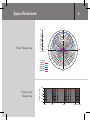
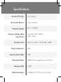
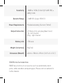
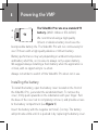
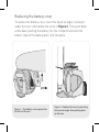
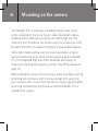
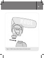
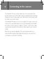
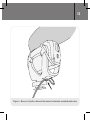
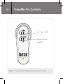
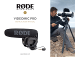
Compact directional
on-camera microphone
www.rodemic.com/videomicpro
INSTRUCTION MANUAL
VideoMic Pro
ENGLISH
1
2
Features
Compact Shotgun Microphone
• Compact, lightweight body
• Broadcast recording quality
• Condenser microphone
• Integrated shock mount provides isolation from
handling/mechanical noise
• Integrated foam windshield
• 3.5mm stereo mini jack output (dual mono)
• Rugged construction
Detailed Control
• Two step high-pass filter (0, 80 Hz)
• Three position level control
(-10dB, 0dB, +20dB)
• LED on / off power indicator
• Integrated billeted metal camera shoe mount
with 3/8” thread for easy boompole mounting
3
High Quality Performance
• 9V battery powered – over 70 hours use (alkaline)
• Low noise circuitry
• Flexible and lightweight cable to minimise handling noise and
ensure isolation
• Australian designed and manufactured
• 10 Year Warranty when you register your microphone (see
below)
Register your VideoMic Pro now and
validate your free 10 year warranty.
Scan the QR code with a smartphone, or visit
www.rodemic.com/warranty
The VideoMic Pro is covered by a limited warranty for one (1) year from the date
of purchase. This can be extended free of charge to a full ten (10) year warranty
by registering your microphone online by visiting our website as above.
General Operation
Shotgun microphones such as the VideoMic Pro have a narrow
pick-up angle or polar response, and so can be used to great effect
with cameras for news gathering, weddings or sporting events.
The VideoMic Pro can be used in any situation where you want to
listen to what’s in the shot, not what’s at the side or out of view.
Regular use of the VideoMic Pro will provide you with better
results as you become more familiar with its sound and pick-up
characteristics.
Specifications
5
0˚
+5.0
Polar Response
0.0
-2.0
-4.0
-6.0
-8.0
-10.0
-12.0
-14.0
-16.0
-18.0
-20.0
-22.0
-24.0
-2.0
-10.0
-20.0
-25.0
90˚
270˚
dB rel. 1V/Pa
Frequency:
500 Hz:
1000 Hz:
2000 Hz:
8000 Hz:
14000 Hz:
180˚
Frequency
Response
dB re 1 V./Pa
10
0
-10
-20
-30
-40
20 Hz
100
1000
10 000 20 000
6
Specifications
Acoustic Principle
Directional Pattern
Frequency Range
Frequency Range (High
Pass Filter)
Variable Level
Line Gradient
Super-Cardioid
40Hz ~ 20 000Hz
Selectable HPF @ 80Hz /
12dB / octave
3 position switch (-10dB, 0dB, +20dB)
Output Impedence
200Ω
Signal to Noise Ratio
74dB
Equivalent Noise
Maximum SPL
Maximum Output
20dBA SPL (A-weighted as per IEC651)
134dB
+6.9dBu (@ 1% THD into 1K Ω load)
Sensitivity
Dynamic Range
Power Requirements
Output Connection
Battery Life
-38dB re 1V/Pa (12.6mV @ 94 dB SPL) ±
2dB @ 1kHz
114dB SPL (as per IEC651)
9V alkaline battery (Current 7.8mA)
3.5 Stereo mini jack plug (dual mono)
Tip - left channel
Ring - right channel
>70 hours
Weight (no battery)
86g (3oz)
Dimension (WxLxH)
43mm x 150mm x 95mm (1.69”x 6”x 3.74”)
Additional accessories
RØDE has a full line of accessories such as windshields, boom
poles, cable extenders and pistol grips. Please visit our website for
further details.
8
+
–
Powering the VMP
9V
The VideoMic Pro runs on a standard 9V
battery. (ANS1:1604A or IEC:6LR61).
We recommend using a high quality
lithium or alkaline battery to achieve the
best possible battery life. The VideoMic Pro will run continuously for
over 70 hours with a high quality alkaline or lithium battery.
Battery performance may vary depending on ambient temperature
and battery shelf life, so it is wise to always carry a spare battery.
We suggest always installing a fresh battery when the application is
critical, with no opportunity to re-shoot.
Always remember to switch off the VideoMic Pro when not in use.
Installing the battery
To install the battery, open the battery cover located on the front of
the VideoMic Pro, just under the windshield foam. To remove the
cover, firmly push upwards on the indentation with your finger. Pull
the base of the cover out to completely remove it, and provide access
to the battery compartment (see Figure 1).
Insert the battery with the negative terminal (-) on top. The battery
will protrude a little until it is pushed in by replacing the battery cover.
Replacing the battery cover
To replace the battery cover, insert the top at an angle, hooking it
under the lever indicated by the arrow in Figure 2. Then push down
at the base (pushing the battery into the compartment) until the
bottom clips of the battery door click into place.
1
2
Figure 1 - The battery cover opens from
the front of the mic.
Figure 2 - Replace the cover by inserting
the top at an angle then pushing down
on the base.
10
Mounting on the camera
The VideoMic Pro incorporates a standard camera shoe mount
on the underside of the shock mount cradle. Designed to reduce
handling and mechanical noise being carried through from the
camera to the microphone, the camera shoe mount also has a 3/8”
thread at the bottom to allow mounting on tripods and boompoles.
Some older model and low cost cameras may produce a higher
level of mechanical noise, which can be picked up by the VideoMic
Pro. The integrated High Pass Filter should be switched on to
reduce the resulting low frequency rumble. (See HPF breakout on
page 13)
Before sliding the camera shoe into place, loosen the fastening ring
by turning anti-clockwise until it is loose enough to fit easily into
your camera’s shoe mount. Once the shoe is in place, gently tighten
by turning the fastening ring clockwise until the VideoMic Pro is
seated firmly in place.
11
Figure 3 - Slide the camera-shoe into place on the camera mount.
12
Connecting to the camera
The VideoMic Pro has a small cable clip on the underside of the
shock mount to secure the cable in place and prevent any unwanted
movement noise. Simply press your cable into the clip / groove until
the cable is secured in place.
The VideoMic Pro delivers a mic level signal to the video camera via
a stereo mini jack audio lead. The mini jack should be connected to
the camera via the camera’s “audio-in” socket – refer to your video
camera user manual for the location of the socket on your camera
model.
Now that you have the VideoMic Pro securely fastened to your
camera and the audio output lead connected, you can switch the
microphone on and start recording.
13
Figure 4 - Be sure to clip the cable onto the mount, to eliminate unwanted cable noise.
14
VideoMic Pro Controls
Off | On | HPF
Level controls
(see p16)
Figure 5 - The controls are located on the end of the mic body.
15
High Pass Filter
The High Pass Filter (HPF) is a low frequency cut-off setting,
which you can use to reduce rumble and other low frequency noise
picked up by the microphone while recording. For more information
about HPF and when it should be used, see the feature on page 18.
To turn on the High Pass Filter, slide the power switch to the right
) symbol is
hand position until it is pointing to where the HPF (
indicated.
LED power indicator
The power indicator LED flashes red briefly when the microphone
is first turned on. This changes to green indicating the battery has
adequate charge. When the battery runs low the LED will remain
red and you should replace the battery. The microphone will
work for over ten hours once the red indicator is lit, however with
reduced performance. We recommend changing the battery as
soon as possible after the LED has turned red.
16
Level controls
The VideoMic Pro features three settings
to control the signal output level to your
recording device. These are set via the
right hand side selector switch on the
back of the microphone.
The left setting (-10) will reduce or attenuate the signal by 10dB,
meaning that loud sound sources will be reduced and be less likely
to overload or ‘clip’ the input of the camera.
The right setting (+20) will increase the signal level by 20dB. This
is useful for recording quiet sound sources, or when your camera
requires a higher input level for better signal to noise ratio (as in
many digital SLR cameras).
Please note that when setting the input level you should always be
mindful of your camera’s internal audio level setting. If you have the
+20dB level selected on the VideoMic Pro you may need to reduce
the input level on your camera.
For best results reduce the camera’s input level as much as
possible, selecting the +20dB input level on the VideoMic Pro and
working downward until the appropriate input level is achieved.
17
This will result in a much lower noise floor and an overall clearer
recording when plugging the VideoMic Pro into the typically low
quality mic preamps found on most DSLR cameras.
The VideoMic Pro has been designed to work best with the
camera’s Auto Gain Control switched off. As always we recommend
you test your audio first before recording anything of importance.
The VideoMic Pro has
been RF/EMI shielded
for very high rejection
of radio frequency
interference, but we
suggest you keep all
transmitters, cell
phones, pagers etc.
at least two metres
away to reduce the
possibility of interference affecting your
recordings.
Loud sound levels can cause
serious hearing damage.
Take care when setting the audio
levels, especially while wearing
headphones.
18
High Pass Filter / HPF
The High Pass Filter is a low frequency cutoff setting, which you
can use to remove rumble, motor noise or other low frequency
noise while recording. It will affect the tone slightly but in some
situations it is required.
For instance, it may be helpful to engage the High Pass Filter to
cut out the sound of air conditioning, handling noise while adjusting
focus settings and distant traffic audible in the background.
You will find that older model and low cost cameras produce more
motor noise, which the VideoMic Pro can pick up. Using the High
Pass Filter setting is also ideal for reducing this.
To engage the High Pass Filter, slide the power switch to the
).
right hand position until it is pointing to the HPF symbol (
The shock mount bands
19
The shock mount uses four elastomer suspension bands to hold
the VideoMic Pro in its shock mount cradle. These bands have been
created to be intentionally soft, to minimise the transmission of
mechanical and handling noise through this material.
If the VideoMic Pro is shaken vigorously or knocked during use, the
microphone body may touch the sides of the shock mount cradle.
This should be avoided as it may add unwanted noise.
During handling or transport, the bands attaching the VideoMic Pro
to its shock mount cradle may become dislodged. They can easily
be put back into place by hand.
Also, if the bands should become damaged or worn over time,
the old bands can be fully removed and replacement bands fitted.
Please follow the instructions below to re-adjust or replace the
bands as necessary.
Before replacing the bands you may wish to first remove the windshield foam, however this is not mandatory. The foam is not present
in the following diagrams for ease of illustration purposes only.
20
Replacing the shock mount bands
Start by attaching your shock mount bands to the microphone body.
The shock mount cradle will then slip easily up under the bands
and support the microphone. Consult Figure 7 to determine which
band to use on the relevant side of the microphone.
There are four bands in total, two of each shape. You will notice the
bands have two ends of different shapes. The larger end is shaped
like an ‘arrow head’ while the smaller end is square. To fit your
band, match the shape of the band to the notches on the VideoMic
Pro’s body.
Figure 6 - There are four bands, two of each shape.
Match the ‘arrow’ shaped ends of the bands to the corresponding
notches at the top of the mic (see Figure 7), and press each firmly
into place until it is secured.
Figure 7 - The ‘arrow head’ shaped ends of the bands go into the
notches on the top of the mic body.
Once the first end is secured, angle the small square end of the
band into the corresponding notch underneath the front or back of
the mic body and press into place. Repeat for all four bands.
Once all four are fitted on the mic body, pull up the shock mount
cradle underneath the bands. Please note the correct alignment
will have the shoe mount on the cradle closer towards the rear of
the microphone (see Figure 9).
Figure 8 - Insert both ends of each band into the mic body, aligning the
tapered squares in the middle of the bands to face inwards.
Next, slide the tapered square on the middle of the band into the
notch on the shock mount. The circular knob on the inner side of
the band will lock into the shock mount notch. Repeat the process
for all four bands, and the VideoMic Pro will be securely mounted to
its shock mount cradle.
Figure 9 - Slide the tapered square in the middle of each band into the
corresponding notch on the mount.
24
Safety and maintenance
• When not in use, always keep your VideoMic Pro in a cool, dry
place, preferably in a camera bag or equivalent to protect from
dust or damage.
• When not in use for long periods of time, always remember to
remove the battery before storage.
• Do not expose the VideoMic Pro to rain or moisture.
Windshield
We recommend leaving the pre-fitted foam windshield on at all
times to protect the microphone from dust and moisture.
In instances where the microphone has become exposed to the
elements and the foam has become moist or dirty, it may be
necessary to remove the foam gently and dry it separately to the
microphone body to prevent moisture from damaging the microphone. Take care in this operation so as not to damage or tear the
foam during removal. The foam windshield can be hand washed in
cold water, then dried thoroughly in the sun before refitting.
25
Moisture absorbent crystals
Inside the VideoMic Pro box, you will find a sachet of moisture
absorbent crystals. Please retain these crystals and store with the
VideoMic Pro to keep the microphone in ideal condition.
Eventually this pack of crystals will need to be dried. This is
indicated by the crystals turning pink in colour. They can easily be
re-used by placing them in an oven at 100-150 degrees Celsius for
approximately ten minutes. The crystals will operate effectively
again once they have turned blue.
The VideoMic Pro has no internal user serviceable parts.
Should you encounter a problem, please refer all servicing to
qualified service personnel.
26
Support
If you experience any problem, or have any questions regarding your
RØDE microphone, first contact the dealer who sold it to you. If the
microphone requires a factory authorised service, return will be
organised by that dealer.
We have an extensive distributor/dealer network, but if you have
difficulty getting the advice or assistance you require, please do not
hesitate to contact us directly.
Alternatively please visit www.rodemic.com/support for contact
details and a list of Frequently Asked Questions.
Importers & distributors
For a full list of international importers and distributors, visit our
website at www.rodemic.com/distributors.
Contact RØDE
International
107 Carnarvon Street
Silverwater NSW 2128 Australia
USA
P.O. Box 4189
Santa Barbara, CA 93140-4189
27