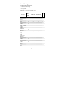
1
0 1 NOTICE:
FCC: This device complies with Part 15 of the FCC Rules,
(1) This device may not cause harmful interface, and
(2) This device must accept any interface received,
including interface that may cause undesirable
operation.
CE: This product conforms to the following standards
EMC:EN55022:2006+A1:2007, class B
EN55024:1998+A1:2001+A2:2003
BSMI: This device is compliant with requirement of BSMI
and granted ID No. R3A078
These limits are designed to provide a reasonable
protection against harmful interface when the equipment is
operated under a commercial environment. This equipment
generates, uses, and can radiate radio frequency energy and,
if not installed and used in accordance with the instruction
manual, may cause harmful interface to radio
communications. Operation of this equipment in a
residential area is likely to cause harmful interface in which
case the user will be required to correct the interface at his
/her own expenses.
Note: All brands and trademarks shall belong to their
respective owner.
Note: Specification is subject to changes without notice.
2 Using the ArgoxScan 9500
The ArgoxScan automatically scan barcode at a distance.
Simply aim and pull the trigger. Code scanning is performed
along the center of the light bar emitted from the reading
window. This bar must cover the entire code.
Successful scanning shall be obtained by tilting the scanner
with respect to the barcode to avoid direct reflections that
impair the reading performance, especially for 2D barcode.
Recommended Steps
When the required settings have been configured, all settings
are stored in non- volatile memory of scanner after reading
configuration barcodes. Label. Recommended steps are as follows.
1)
Set right host interface for your scanner.
2)
Set interface to optimize protocol of scanner with your
host in interface section.
3)
Set system control of scanner, such as specific
adjustments double confirm, power saving, indicator
and scanning mode which you prefer usage in system
control section.
4)
Set code options of scanner for your usage in code
option section. You must make sure to enable the
symbology first, then Min./Max. code length, code ID
checksum and truncate digits are also converted.
5)
Set string format of the scanner, such as preamble,
postamble Prefix, suffix, code ID and code name
transmission for your application in string format
section.
Note: If still not work properly. Please contact your dealer for
further information.
3 CONTENTS Introduction ................................................................................... 8 Default Setting................................................................... 9 AS-9500 Specification..................................................... 11 Reading Skills of AS-9500 .............................................. 14 Programming AS-9500 .................................................... 15 Interface Selection ........................................................... 16 RS-232............................................................................. 18 USB HID ......................................................................... 22 USB Virtual COM ........................................................... 22 Pin Assignments .............................................................. 23 System Control ............................................................................ 25 Scan ................................................................................. 25 Indication......................................................................... 30 Thermal and Centering .................................................... 38 Decode Search Mode ....................................................... 41 Output Sequence.............................................................. 42 Print Contrast................................................................... 48 Video Reverse ................................................................. 48 Working Orientation........................................................ 49 Code Option ................................................................................ 50 Codabar ........................................................................... 51 Code 39............................................................................ 53 Code 32............................................................................ 56 Interleaved 2 of 5 ............................................................. 57 4 Code 93............................................................................ 58 Straight 2 of 5 Industrial .................................................. 59 Straight 2 of 5 IATA........................................................ 60 Matrix 2 of 5 .................................................................... 61 Code 11............................................................................ 62 Code 128.......................................................................... 64 Telepen ............................................................................ 66 UPC-A ............................................................................. 67 UPC-E0 ........................................................................... 70 EAN/JAN-13 ................................................................... 73 EAN/JAN-8 ..................................................................... 75 MSI.................................................................................. 77 Plessey Code.................................................................... 78 GS1 DataBar Omnidirectional ......................................... 79 GS1 DataBar Limited ...................................................... 79 GS1 DataBar Expanded ................................................... 80 PosiCode.......................................................................... 81 Codablock F..................................................................... 82 Code 16K......................................................................... 83 Code 49............................................................................ 84 PDF417............................................................................ 85 MicroPDF417 .................................................................. 86 EAN•UCC Composite Codes .......................................... 87 Postal Codes .................................................................... 89 QR Code .......................................................................... 93 Data Matrix...................................................................... 94 5 MaxiCode ........................................................................ 95 Aztec Code ...................................................................... 96 Chinese Sensible (Han Xin) Code.................................... 97 String Format............................................................................... 98 Prefix/Suffix .................................................................... 98 Data Formatting ............................................................. 104 Data Format Editor Commands ..................................... 107 Imaging Commands....................................................... 111 OCR Programming ........................................................ 120 OCR Templates ............................................................. 124 Utilities .......................................................................... 138 Test Chart....................................................................... 140 Interface ID.................................................................... 145 Product Code ID ............................................................ 146 ASCII Code Table.......................................................... 148 OCR Programming Chart .............................................. 150 Program Chart ............................................................... 151 6 7 Introduction
Installation
RS-232
1)
Disconnect power to the terminal/computer.
2)
Connect the external power supply (DC adapter) to the serial
interface cable of the scanner.
3)
Plug the serial connector into the serial port on the back
of your computer/terminal. Tighten the two screws to secure
the connector to the port.
4)
Plug the power pack into power source.
5)
Once the scanner has been fully connected, turn the
terminal / computer power back on.
USB (HID)
1)
Connect the USB cable between scanner and PC.
2)
Windows will automatically detect the USB device.
1)
Install driver, USB Virtual COM Driver, from CD-ROM,
USB (Virtual-COM)
The driver will use the next available COM port
number
2)
Connect the USB cable between scanner and PC.
3)
Windows will automatically detect the USB device.
Note: If any of the above operation is incorrect, turn off the
power immediately and check any improper
connections. Go through all above steps again
.
8 Default Setting
For each barcode shown as below:
V = Enabled as default setting
- = Not supported
Empty space = Not enabled at default setting
Code Type
UPC-A
UPC-E0
UPC-E1
EAN-13
EAN-8
Code-32
Code-39
TCIF
Linked
Code 39
Code-49
Interleaved
2 of 5
Industrial
2 of 5
Straight 2 of 5
IATA
Straight 2 of 5
Industrial
Matrix 2 of 5
Codabar
Code-128
Code-93
Code-11
Telepen
MSI
Plessey
Read
Enable
Checksum
Verification
Enable
Checksum
Transmission
Enable
V
V
V
V
V
V
V
V
V
V
V
V
V
Code
ID
c
E
E
d
D
<
b
T
I
V
e
-
-
e
f
f
V
V
V
V two digits
9 m
a
j
i
h
t
g
n
GS1 DataBar
Omnidirectional
GS1 DataBar
Limited
GS1 DataBar
Expanded
PosiCode A&B
Codablock F
Code 16K
Code 49
PDF 417
MicroPDF 417
EAN UCC
Composite
Postnet
Planet Code
British Post
Canadia Post
Kix Post
(Netherlands)
Australian Post
Japanese Post
China Post
Korea Post
QR Code
Data Matrix
MaxiCode
Aztec Code
Aztec Runes
V
-
-
y
V
-
-
y
V
-
-
y
V
W
q
o
I
r
R
V
V
V
y
P
L
B
C
K
A
J
Q
?
O
w
x
z
z
V
V
V
V
10 AS-9500 Specification
ArgoScan 9500 series
Specification
AS-9500g
AS-9500HD
AS-9500L
Operational
Light Source
626 nm ± 30 nm Visible Red LED
Aiming Source
526 nm ± 30 nm Visible Green LED
Optical System
752 x 480 CMOS sensor
Motion Tolerance
4 inches / sec
Depth of Scan Field
(PCS=90%,10 mils,
37~175 mm
33~102mm
67~176mm
62~137 mm
34~101mm
85~168mm
1D
5mil
4mil
6.6mil
2D
8.3mil
6.7mil
15mil
1D : Code 39)
Depth of Scan Field
(PCS=90%,10 mils,
2D : QR Code)
Resolution
Print Contrast
25% or more
Focal Point
114 mm
114mm
114mm
(from lens plate)
Scanning Angle
Pitch: ± 40° Skew: ±40°
Rotational Sensitivity
360˚
Auto-discriminates all standard barcodes;
Decode Capability
Other symbologies can be ordered
optionally
Beeper Operation
Volume x 3 and Frequency x 3 or no beep
Indicator
Blue led, vibrator, and adjustable beeper
Mechanical
Length
165.1 mm
11 Width-handle
32 mm
Width-head
72.8 mm
Depth-handle
54.7 mm
Depth-head
82.5 mm
Weight
146 g
Cable
Straight 2.0 m
Connector type
RJ-45 phone jack connector
Case material
ABS and Rubber
Electrical
Input Voltage
Power
Operating
3.7 ~ 5.5 VDC
RS232
USB HID
Max 350mA @ 5V
Standby
Max 65mA@ 5V
Max 60mA@ 5V
Low Power Mode
Max 40mA@5V
*
Agency listing
EMI: FCC, CE, BSMI
Safety: UL, BSMI, CB
Environmental
Operating
0℃ to 50℃
Temperature
(32℉ to 122℉)
-20℃ to 60℃
Storage Temperature
Humidity
Light Level
Shock
(-4℉ to 140℉)
Up to 95% relative humidity,
non-condensing @ 50℃
Dark to 100,000 Lux.
24 drops from 1.8 m to concrete
Resistance
Contaminants
IP 42
Seals to resist airborne particulate
contaminants
Ventilation
None required
12 Programming
1. Executing DOS Command by RS-232 or
Programming
USB Virtual COM.
method
2. A scanner reads the programming codes.
Program upgrade
Enabled built-in flash memory
Code type selection, check digit selection
Decoding option Decoding option
Transmitted character delay, Header
selection, trailer selection, message suffix,
good read beep tone and volume, scanner
Programmable
trigger selection
characteristics
Keyboard emulation type (intermessage
delay, keyboard type and keyboard
language)
Serial interface type (ACK/NAK,
Xon/Xoff, RTS/CTS, good read LED
control, start/stop bits)
13 Reading Skills of AS-9500
The engine has a view finder that projects a bright red or
green aiming beam that corresponds to the engine’s
horizontal field of view. The aiming beam should be centered
over the bar code, but it can be positioned in any direction for
a good read.
Linear bar code
2D Symbol
The aiming beam is smaller when the engine is closer to the
code and larger when it is farther from the code. Symbologies with
smaller bars or elements (mil size) should be read closer to the unit.
Symbologies with larger bars or elements (mil size) should be read
farther from the unit. To read single or multiple symbols Linear
bar code 2D Matrix symbol (on a page or on an object), hold the
engine at an appropriate distance from the target, send a trigger
command, and center the aiming beam on the symbol. If the
code being scanned is highly reflective (e.g., laminated), it may be
necessary to tilt the code +5° to prevent unwanted reflection.
14 Programming AS-9500 Series Scanner
To program the AS- 9500, you must scan a series of programming
barcodes in the correct order. Fold out the back cover of this
manual. You will see a table of alphanumeric barcodes, which are
used to program the various options presented.
To program each option, you must:
1. Scan the Program barcodes.
2. Enter the option mode by scanning the option barcodes
3. The necessary alphanumeric inputs are listed. Scan these
alphanumeric entries from the Program Chart. To confirm
above steps, you must scan the Save barcode.
.
15 Interface Selection
This decoder built-in scanner comes in one model and
supports interfaces such as RS232 serial, USB virtual COM
and USB HID. In most of the cases, simply selecting an
appropriate cable and configure the proper interface by following
interface selection.
Interface selection: You can change factory interface default
(USB Virtual COM ) for other type interface. By plugging
different cables, setting right interface, then scan the interface
barcode, power cycle the scanner will be changed to another
interface. However, you must make sure which cable you need.
RS-232 Interface
USB HID (PC)
USB HID (MAC)
*USB Virtual COM
16 17 RS-232
Default Setting
Baud Rate
115200 bps
Data Format
8 data bits, no parity bit, 1 stop bit
Baud Rate
300
9600
600
19200
1200
38400
2400
57600
4800
*115200
18 Data Bits sets the word length at 7 or 8 bits of data per character.
If an application requires only ASCII Hex characters 0 through 7F
decimal (text, digits, and punctuation), select 7 data bits. For
applications which require use of the full ASCII set, select 8 data
bits per character. Default = 8.
Stop Bits sets the stop bits at 1 or 2. Default = 1.
Parity provides a means of checking character bit patterns for
validity. Default = None.
Data Format
7 Data,1 Stop, Parity Even
7 Data,2 Stop, Parity Odd
7 Data,1 Stop, Parity None
8 Data,1 Stop, Parity Even
7 Data,1 Stop, Parity Odd
*8 Data,1 Stop, Parity None
7 Data,2 Stop, Parity Even
8 Data,1 Stop, Parity Odd
7 Data,2 Stop, Parity None
19 RS-232
RTS/CTS-If the scanner wants to send the barcode data to
host computer, it will issue the RTS signal first, wait for the
CTS signal from the host computer, and then perform the
normal data communication. If there is no replied CTS signal
from the host computer after the timeout (Response Delay)
duration, the scanner halts transmission until it detects another
active CTS signal.
Xon/Xoff- When the host computer is unable to accept data, it
sends a Xoff code to inform the scanner to suspend data
transmission, and Xon to continue.
ACK/NAK- When the ACK/NAK protocol is used, the scanner
waits for an ACK (acknowledge) or (not acknowledge) from the
host computer after data transmission, and will resend in response
to a NAK.
Response Delay
The unit stays awake to receive data until the RS-232
Receiver Time-Out expires. A trigger command resets the
time-out. When an RS-232 receiver is sleeping, a character
may be sent to wake up the receiver and reset the time-out.
A transaction on the CTS line will also wake up the receiver.
The receiver takes 300 milliseconds to completely come up.
Change the RS-232 receiver time-out by scanning the bar code
below, then scanning digits from the inside back cover
of this manual, then scanning Save. The range is 0 to 300
seconds. Default = 0 seconds (no time-out - always on).
20 Handshaking
RTS/CTS On
*RTS/CTS Off
XON/XOFF On
*XON/OFF Off
ACK/NAK On
*ACK/NAK Off
Response Delay
21 USB HID
Scan the following code to program the AS-9500 for USB HID bar
code imagers.
USB HID (PC)
USB HID (MAC)
USB Virtual COM
Scan the following code to program the AS-9500 to emulate a
regular RS-232-based COM port. If you are using a PC, you will
need to download a driver from CD-ROM, The driver will use the
next available COM port number
USB Virtual COM
CTS/RTS Emulation & ACK/NAK Mode
CTS/RTS On
*CTS/RTS Off
ACK/NAK On
*ACK/NAK Off
22 Pin Assignments
1 2 3 4 5 6 7 8 9 10 10-pin RJ-45 Connector to Scanner Side
Pin
RS-232
1
NC
USB
NC
2
VCC
VCC
3
TXD
TXD
4
NC
NC
5
NC
NC
6
CTS
D+
7
RXD
D-
8
RTS
RTS
9
GND
GND
10
GND
GND
23 Pin Assignments
5 4 3 2 1 9 8 7 6 1
4
Connector to Host Side:
Pin
RS-232
USB
1
NC
+5V
2
TXD
D-
3
RXD
D+
4
NC
GND
5
GND
*
6
NC
*
7
CTS
*
8
RTS
*
9
VCC
*
24 System Control
Scan
Scanning output:
You can set the image size to a VGA resolution to accommodate
older applications that require a smaller image size. When Image
VGA is set to On, the resultant image is 640x480 pixels. When
Image VGA is Off, the image is 752x480 pixels.
Scanning mode:
Manual/Serial Trigger Mode
When in manual trigger mode, the imager scans until a bar code is
read, or until the hardware trigger is released.
When in serial mode, the imager scans until a bar code has been
read or until the deactivate command is sent. In serial mode, the
imager can also be set to turn itself off after a specified time has
elapsed (see Read Time-Out, which follows).
Manual Trigger, Low Power (For RS-232 only)
The imager powers down until the trigger is pulled. When the
trigger is pulled, the imager powers up and operates until there is
no triggering for the time set with the Low Power Time-Out bar
code below. There is a delay of up to one second in operation
when the imager is first triggered, but there is no delay when
operating in low power time-out mode.
25 Scan
Auto-sense Mode
This programs the imager to work in Auto-sense mode. The LEDs
are either off or at the lowest power for ambient conditions until a
bar code is presented to the imager. Then the LEDs turn on
automatically to read the code. Auto-sense Mode uses ambient
light to detect the bar codes. If the light level in the room is not
high enough, Auto-sense Mode may not work properly.
Snap and Ship
Snap and Ship mode allows you to bypass the decoder and ship an
image directly to the host. In this mode, an image is taken and
shipped upon each trigger pull, instead of being sent to the decoder.
Snap and Ship is useful when you are using your own decoder.
Note: Snap and Ship mode only works if the imager is connected
via an RS-232 serial port or via a USB keyboard. If you use Snap
and Ship when the imager is connected to another interface, it calls
the decoder after each image ship, but only to look for menu
codes.
26 Scanning Output
VGA Off
*VGA On
Scanning Mode
*Manual/Serial Trigger
Manual Trigger, Low Power
Auto-sense Mode
Snap and Ship
27 Scan
Read Time-Out
Use this selection to set a time-out (in milliseconds) of the
imager’s trigger if the imager is in manual trigger mode. Once the
imager has timed out, you can activate the imager by pressing the
trigger. After scanning the Read Time-Out bar code, set the
time-out duration (from 0-300,000 milliseconds) by scanning
digits from the inside back cover, then scanning Save. Default = 0
(infinite, or no time-out).
Low Power Time-Out Timer
Scan the Low Power Time-Out bar code to change the time-out
duration (in seconds). Then scan the time-out duration (from 0-300
seconds) from the inside back cover, and Save. Default = 120
seconds. If the unit remains idle during the low power time-out
interval, the unit goes into low power mode. Whenever the trigger
is enabled, the low power time-out timer is reset.
Auto-sense LED Behavior after Decode
When an imager is in Auto-sense mode, the LEDs remain on and
continue scanning for a short time after a bar code is decoded. If
you wish to turn the LEDs off immediately after a bar code is
decoded, scan the LEDs Off bar code, below. Default = LEDs On.
Auto-sense LED Time-Out
When using Auto-sense LED Behavior after Decode , you may
want to set the time the LEDs remain off after a decode. To set the
duration of this delay, scan the bar code below, then set the
time-out by scanning digits (0 - 9,999 ms) , then scanning Save.
Once the unit has completed this time-out, it will immediately
resume scanning.
Auto-sense Sensitivity
Auto-sense Sensitivity is a numeric range that increases or
decreases the imager's reaction time to bar code Auto-sense. To set
the sensitivity, scan the Sensitivity bar code, then scan the degree
28 of sensitivity (from 0-20) from the inside back cover, and Save. 0
is the most sensitive setting, and 20 is the least sensitive.
Default = 1.
Hands Free Time-Out
The Auto-sense Modes is referred to as “hands free” modes. If the
hardware trigger is pulled when using a hands free mode, the
imager changes to manual trigger mode. You can set the time the
imager should remain in manual trigger mode by setting the Hands
Free Time-Out. Once the time-out value is reached, (if there have
been no further trigger pulls) the imager reverts to the original
hands free mode. Scan the Hands Free Time-Out bar code, then
scan the time-out duration (from 0-300,000 milliseconds) from the
inside back cover, and Save. Default = 5,000 ms.
Read Time out
Read Time-Out
Low Power Time-Out
Auto-sense
*LEDs On
LEDs Off
LED Time-Out
LED Time-Out Duration
Sensitivity
Hands Free Time-Out
29 Indication
Beeper
The beeper may be programmed On or Off in response to a good
read. Turning this option off, only turns off the beeper response to
a good read indication. All error and menu beeps are still audible.
Volume
The beeper volume codes modify the volume of the beep the
imager emits on a good read.
Frequency
The beeper pitch codes modify the pitch of the beep the imager
emits on a good read.
Duration
The beeper duration codes modify the length of the beep the
imager emits on a good read.
Beeper
*On
Off
Volume
Low
*Medium
High
Extreme Low
Frequency
Low
High
*Medium
Duration
*Normal Beep
Short Beep
30 LED
The LED indicator can not be programmed On or Off in response
to a good read. If user turned off vibrator and beeper, then the LED
indicator will be Off. But when either vibrator or beeper is ON,
then the LED indicator will remain On all the time.
Vibrator
The vibrator provides a unique feature to AS-9500 that user can
understand whether the data is well scanned and sent to Host PC
under an adverse circumstance that the beep sound may not be
heard, or a circumstance requiring extreme quiet that the beep
sounds are not allowed.
Vibrator
*On
Off
31 Indication
Illumination Lights
If you want the illumination lights on while reading a bar code,
scan the Lights On bar code, below. However, if you want to turn
just the lights off, scan the Lights Off bar code.
Note: This setting does not affect the aimer light. The aiming light
can be set using Aimer Modes.
Imager Time-Out
Imager Time-Out powers down the imager after the unit has been
idle for the specified time. To prevent the imager from powering
down, set this time-out to 0. Scan the bar code below, then set the
time-out by scanning digits (from 0 -999,999 ms) from the inside
back cover, then scanning Save. Default = 1 ms.
Reread Delay
This sets the time period before the imager can read the same bar
code a second time. Setting a reread delay protects against
accidental rereads of the same barcode. Longer delays are effective
in minimizing accidental rereads at POS (point of sale). Use
shorter delays in applications where repetitive bar code scanning is
required. Reread Delay only works when in Auto-sense Mode
32 User-Specified Reread Delay
If you want to set your own length for the reread delay, scan the
bar code below, then set the delay (from 0-30,000 milliseconds) by
scanning digits from the inside back cover, then scanning Save.
Illumination Light
*Lights On
Lights Off
Imager Time-Out
Imager Time-Out
Reread Delay
Short (500 ms)
*Medium (750ms)
Long (1000 ms)
Extra Long (2000 ms)
User-Specified Reread Delay
User-Specified Reread Delay
33 Indication
Aimer Delay
The aimer delay allows a delay time for the operator to aim the
imager before the picture is taken. Use these codes to set the time
between when the trigger is activated and when the picture is taken.
During the delay time, the aiming light will appear, but the LEDs
won’t turn on until the delay time is over.
User-Specified Aimer Delay
If you want to set your own length for the duration of the delay,
scan the bar code below, then set the time-out by scanning digits (0
- 4,000 ms) from the back cover of this manual, then scan Save.
Aimer Modes
Interlaced, the illumination and aiming timing is automatically
synchronized to the imager exposure period by the Image Engine.
The engine turns illumination on while the image is being exposed,
and it turns the aiming off at all other times. The interlaced mode
provides the lowest overall current draw and is recommended for
most applications. It also provides the brightest aimer in most
applications. The Image Engine software automatically maintains
an approximate 25% aimer duty cycle, even when the imager
exposure time is at its maximum in dark operating environments.
Concurrent is provided for backwards compatibility with the
4X00 Image Engine series, and is not recommended for most
applications. In concurrent mode, the illumination LEDs are on
continuously, while the aimer LEDs turn off during the imager
exposure period, and on while the imager is not exposing.
Concurrent mode is used to eliminate any flicker of the
illumination LEDs that may be objectionable to the user,
especially when running the engine at 12 MHz. The illumination
LED current is reduced compared to interlaced mode to limit
engine peak current. The image engine software automatically
maintains an approximate 25% aimer duty cycle, even when the
imager exposure time is at its maximum in dark operating
34 environments. Concurrent mode provides the brightest appearance
of the illumination LEDs of any of the imager operating modes.
This mode may be useful for applications when an operator is
using the illumination LEDs for aiming, such as in fixed mount,
kiosk, or auto trigger applications. Select Off if you don’t want to
use either aimer mode.
Aimer Delay
200Milliseconds
400Milliseconds
*Off ( no delay)
Delay Duration
Aimer Modes
Concurrent
*Interlaced
Off
35 Indication
Number of Beeps
The number of beeps of a good read can be programmed from 1 9. The same number of beeps will be applied to the beeper and
LED in response to a good read. For example, if you program this
option to have five beeps, there will be five beeps and five LED
flashes in response to a good read. The beeps and LED flashes are
in sync with one another. To change the number of beeps, scan the
bar code below and then scan a digit (1-9) bar code and the Save
bar code.
Good Read Delay
This sets the minimum amount of time before the imager can read
another bar code. Default = No Delay.
User-Specified Good Read Delay
If you want to set your own length for the good read delay, scan
the bar code below, then set the delay (from 0-30,000 milliseconds)
by scanning digits from the inside back cover, then scanning Save.
36 Number of Beep
Number of Pulses
Good Read Delay
*No Delay
Short Delay (500 ms)
Medium Delay (1,000 ms)
Long Delay (1,500 ms)
User-Specified Good Read Delay
User-Specified Good Read Delay
37 Thermal and Centering
Thermal Considerations
Care must be taken when designing the Image Engine into any
system. Internal heating of the Image Engine can occur in high
duty cycle scanning applications in several ways. The high
visibility aimer dissipates a significant amount of power as heat.
The illumination and aiming LEDs also release heat, and are a
major contributor to thermal increases in high use or in Auto-sense
mode. An increase in temperature around an Image Engine can
cause noise levels on the imager, degrading image quality. The
thermal rise can also affect the laser diode. In a continuous
scanning or high use environment, the Image Engine temperature
can rise 15° to 20°C. Under high ambient temperature conditions,
the laser diode is at risk of thermal breakdown and possible failure.
The image quality and decode performance will also degrade. The
Power Control PWM can be used to reduce the effect of the
Illumination LEDs on thermal rise, however, this also reduces the
intensity of the illumination. Reducing the intensity of the
illumination reduces total power used but can also reduce the
depth of field in low light environments.
Centering
Use Centering to narrow the imager’s field of view to make sure
the imager reads only those bar codes intended by the user. For
instance, if multiple codes are placed closely together, centering
will insure that only the desired codes are read. (Centering can be
used in conjunction with Aimer Delay, for the most error-free
operation in applications where multiple codes are spaced closely
together. Using the Aimer Delay and Centering features, the
imager can emulate the operation of older systems, such as linear
laser bar code imagers. In the example below, the gray area is the
full imager field of view and the white area is the centering
window. Bar Code 1 will not be read, while Bar Code 2 will be.
38 The default centering window is a 128x96 pixel area (640x480
default image size) in the center of the imager’s field of view. The
following diagram illustrates the default top, bottom, left, and right
pixel positions, measured from the top and the left side of the
imager’s field of view.
39 Thermal and Centering
If a bar code is not within the predefined window, it will not be
decoded or output by the imager. If centering is turned on by
scanning Centering On, the imager only reads codes that intersect
the centering window you specify using the Top, Bottom, Left, or
Right bar codes. Scan Centering On, then scan one of the
following bar codes to change the top, bottom, left, or right of the
centering window. Then scan the percent you want to shift the
centering window using digits on the inside back cover of this
manual. Scan Save. Default Centering = 40% for Top and Left,
60% for Bottom and Right.
Centering On
*Centering Off
Top of Centering Window
Bottom of Centering Window
Left of Centering Window
Right of Centering Window
40 Decode Search Mode
There are three selectable decode (scanning) modes:
Full Omnidirectional - Searches for bar code features beginning
at the center of an image, and searches to the image’s limits. This
mode reads all symbologies, in any orientation. The Full
Omnidirectional search is very thorough which may slow
performance time.
Quick Omnidirectional - This is an abbreviated search for bar
code features around the center region of an image. This mode
quickly reads all symbologies in any orientation. The Quick
Omnidirectional mode may miss some off-center
symbols, as well as larger Data Matrix and QR Code.
Advanced Linear Decoding - Performs quick horizontal linear
scans in a center band of the image. This mode does quickly read
linear and stacked bar codes. Advanced Linear Decoding cannot
read 2D, OCR, or Postal symbols.
Note: This search mode is the
Full Omni-directional
default setting for the 2D
AS-9500 series Engines.
Quick Omni-directional
Note: This search mode is the
Advanced Linear Decoding
default setting for the
point-and-shoot AS-9500
41 Output Sequence
Require Output Sequence
When turned off, the bar code data will be output to the host as the
Imager decodes it. When turned on, all output data must conform
to an edited sequence or the Imager will not transmit the output
data to the host device.
Note: This selection is unavailable when the Multiple Symbols
Selection is turned on.
Output Sequence Editor
This programming selection allows you to program the Imager to
output data (when scanning more than one symbol) in whatever
order your application requires, regardless of the order in which
the bar codes are scanned. Reading the Default Sequence symbol
programs the Imager to the Universal values, shown below. These
are the defaults. Be certain you want to delete or clear all formats
before you read the Default Sequence symbol.
Note: To make Output Sequence Editor selections, you’ll need to
know the code I.D., code length, and character matches your
application requires. Use the Alphanumeric symbols (inside back
cover) to read these options.
Note: You must hold the trigger while reading each bar code in the
sequence.
To Add an Output Sequence
1. Scan the Enter Sequence symbol
2. Code I.D.
On the Product Code ID, find the symbology to which you want to
apply the output sequence format. Locate the Hex value for that
symbology and scan the 2 digit hex value from the Programming
Chart (inside back cover).
3. Length
Specify what length (up to 9999 characters) of data output will be
acceptable for this symbology. Scan the four digit data length from
the Programming Chart. (Note: 50 characters is entered as 0050.
9999 is a universal number, indicating all lengths.) When
42 calculating the length, you must count any programmed prefixes,
suffixes, or formatted characters as part of the length (unless using
9999).
4. Character Match Sequences
On the ASCII Chart , find the Hex value that represents the
character(s) you want to match. Use the Programming Chart to
read the alphanumeric combination that represents the ASCII
characters. (99 is the Universal number, indicating all characters.)
5. End Output Sequence Editor
Scan F F to enter an Output Sequence for an additional
symbology, or Save to save your entries. Other Programming
Selections
•Discard
This exits without saving any Output Sequence changes.
43 Output Sequence
Output Sequence Example
In this example, you are scanning Code 93, Code 128, and Code
39 bar codes, but you want the imager to output Code 39 1st, Code
128 2nd, and Code 93 3rd, as shown below.
Note: Code 93 must be enabled to use this example.
You would set up the sequence editor with the following command
line:
SEQBLK62999941FF6A999942FF69999943FF
The breakdown of the command line is shown below:
SEQBLKsequence editor start command 62 code identifier for
Code 39 9999 code length that must match for Code 39, 9999 = all
lengths 41 start character match for Code 39,
41h = “A” FF termination string for first code
6A code identifier for Code 128 9999 code length that must match
for Code 128,
9999 = all lengths 42 start character match for Code 128,
42h = “B” FF termination string for second code
69 code identifier for Code 93
9999 code length that must match for Code 93,
9999 = all lengths 43 start character match for Code 93,
44 43h = “C”
FF termination string for third code To program the previous
example using specific lengths, you would have to count any
programmed prefixes, suffixes, or formatted characters as part of
the length. SEQBLK62001241FF6A001342FF69001243FF
The breakdown of the command line is shown below:
SEQBLK sequence editor start command
62 code identifier for Code 39
0012 A - Code 39 sample length (11) plus CR suffix (1) = 12
41 start character match for Code 39, 41h = “A”
FF termination string for first code
6A code identifier for Code 128
0013 B - Code 128 sample length (12) plus CR suffix (1) = 13
42 start character match for Code 128, 42h = “B”
FF termination string for second code
69 code identifier for Code 93
0012 C - Code 93 sample length (11) plus CR suffix (1) = 12
43 start character match for Code 93, 43h = “C”
FF termination string for third code
45 Output Sequence
Require Output Sequence
When an output sequence is Required, all output data must
conform to an edited sequence or the imager will not transmit the
output data to the host device. When it’s On/Not Required, the
imager will attempt to get the output data to conform to an edited
sequence, but if it cannot, the imager transmits all output data to
the host device as is. When the output sequence is Off, the bar
code data is output to the host as the imager decodes it.
Note: This selection is unavailable when the Multiple Symbols
Selection is turned on.
Output Sequence Editor
Enter Sequence
Default Sequence
Require Output Sequence
Required
On/Not Required
*Off
46 Multiple Symbols
When this programming selection is turned On, it allows you to
read multiple symbols when the trigger is activated. If you press
and hold the trigger, aiming the Imager at a series of symbols, it
reads unique symbols once, beeping (if turned on) for each read.
The imager attempts to find and decode new symbols as long as
the trigger is activated. When this programming selection is turned
Off, the Imager will only read the symbol closest to the aiming
beam.
No Read
With No Read turned On, the Imager notifies you if a code cannot
be read. If using a Quick*View Scan Data Window, an “NR”
appears when a code cannot be read. If No Read is turned Off, the
“NR” will not appear.
Multiple Symbols
Note: This feature does not
work when the Imager is in
Low Power mode.
On
*Off
No Read
On
*Off
47 Print Contrast
Print Contrast is used to adjust the way the imager reads Matrix
symbols. If an imager will be seeing consistently heavily printed
matrix symbols, then a Print Contrast of 6 may improve the
reading performance. For consistently light printing, a Print
Contrast of 2 may help. After scanning the Set Print Contrast bar
code, set the Print Contrast (from 1-7) by scanning digits from the
inside back cover, then scanning Save. Default = 4.
Print Contrast
Set Print Contrast
*Default
Video Reverse
Video Reverse is used to allow the imager to read bar codes that
are inverted. The “Off” bar code below is an example of this type
of bar code. If additional menuing is required, Video Reverse must
be disabled to read the menu bar codes and then re-enabled after
menuing is completed.
Note: Images downloaded from the unit will not be reversed. This
is a setting for decoding only.
Video Reverse
On
48 Working Orientation
Some bar codes are direction-sensitive. For example, Kix codes
and OCR can misread when scanned sideways or upside down.
Use the working orientation settings if your direction-sensitive
codes will not usually be presented upright to the scanner. Default
= Upright.
Working Orientation
*Upright
Rotate Clockwise 90°
Upside Down
Rotate Counterclockwise 90°
49 Code Option
If you want to decode all the symbologies allowable for your
imager, scan the All Symbologies On code. On the other hand,
you want to decode only a particular symbology, scan All
Symbologies Off followed by the On symbol for that particular
symbology.
All Symbologies
All Symbologies On
All Symbologies Off
Message Length Description
You may set the valid reading length of some of the bar code
symbologies. If the data length of the scanned bar code doesn’t
match the valid reading length, the imager will issue an error beep.
You may set the same value for minimum and maximum length to
force the imager to read fixed length bar code data. This helps
reduce the chances of a misread.
EXAMPLE: Decode only those bar codes with a count of 9-20
characters. Min. length = 09 Max. length = 20
EXAMPLE: Decode only those bar codes with a count of 15
characters. Min. length = 15 Max. length = 15. For a value other
than the minimum and maximum message length defaults, scan the
bar codes included in the explanation of the symbology, then scan
the digit value of the message length and Save bar codes. The
minimum and maximum lengths and the defaults are included with
the respective symbologies
Start/Stop Characters
Start/Stop characters identify the leading and trailing ends of
the bar code.
50 Codabar
Check Character
Codabar check characters are created using different “modulos.”
You can program the imager to read only Codabar bar codes with
Modulo 16 check characters. No Check Character indicates that
the imager reads and transmits bar code data with or without a
check character. When Check Character is set to Validate and
Transmit, the imager will only read Codabar bar codes printed
with a check character, and will transmit this character at the end
of the scanned data. When Check Character is set to Validate, but
Don’t Transmit, the unit will only read Codabar bar codes printed
with a check character, but will not transmit the check character
with the scanned data.
<Default All Codabar Settings>
*On
Off
Start /Stop Character
Transmit
*Don’t Transmit
Check Character
*No Check Character
Validate and Transmit
Validate Modulo 16 and
Transmit
Validate Modulo 16 ,but Don’t
Transmit
51 Codabar
Concatenation
Codabar supports symbol concatenation. When you enable
concatenation, the imager looks for a Codabar symbol having a
“D” start character, adjacent to a symbol having a “D” stop
character. In this case the two messages are concatenated into one
with the “D” characters omitted. Default = On.
Select Require to prevent the imager from decoding a single
“D” Codabar symbol without its companion. This selection
has no effect on Codabar symbols without Stop/Start D
characters.
Message Length
Scan the bar codes below to change the message length. Minimum
and Maximum lengths = 2-60. Minimum Default = 4, Maximum
Default = 60.
Message Length
*On
Off
Require
Minimum Message Length
Maximum Message Length
52 Code 39
Start/Stop Characters
Start/Stop characters identify the leading and trailing ends of
the bar code. Youmay either transmit, or not transmit
Start/Stop characters. Default = Don’t Transmit.
Check Character
No Check Character indicates that the imager reads and
transmits bar code data with or without a check character
When Check Character is set to Validate, but Don’t Transmit,
the unit only reads Code 39 bar codes printed with a check
character, but will not transmit the check character with the
scanned data. When Check Character is set to Validate and
Transmit, the imager only reads Code 39 bar codes printed
with a check character, and will transmit this character at the
end of the scanned data. Default = No Check Character.
<Default All Code 39 Settings>
*On
Off
Transmit
*Don’t Transmit
*No Check Character
Validate and Transmit
Validate, but Don’t Transmit
53 Code 39
Message Length
Scan the bar codes below to change the message length.. Minimum
and Maximum lengths = 0-48. Minimum Default = 0, Maximum
Default = 48.
Append
This function allows the imager to append the data from several
Code 39 bar codes together before transmitting them to the host
computer. When this function is enabled, the imager stores those
Code 39 bar codes that start with a space (excluding the start and
stop symbols), and does not immediately transmit the data. The
imager stores the data in the order in which the bar codes are read,
deleting the first space from each. The imager transmits the
appended data when it reads a Code 39 bar code that starts with a
character other than a space.
Code 39
Minimum Message Length
Maximum Message Length
Append On
*Append Off
54 Full ASCII
If Full ASCII Code 39 decoding is enabled, certain character
pairs within the bar code symbol will be interpreted as a single
character. For example: $V will be decoded as the ASCII character
SYN, and /C will be decoded as the ASCII character #.
Character pairs /M and /N decode as a minus sign and period
respectively. Character pairs /P through /Y decode as 0 through 9.
55 Code 39
Code Page
Code pages define the mapping of character codes to
characters. If the data received does not display with the proper
characters, it may be because the barcode being scanned was
created using a code page that is different from the one the host
program is expecting. If this is the case, scan the bar code below,
select the code page with which the bar codes were created and
scan the value and the Save bar code. The data characters should
then appear properly.
Full ASCII On
*Full ASCII Off
Code 39 Code Page
Code 32
Code 32 Pharmaceutical is a form of the Code 39 symbology
used by Italian pharmacies. This symbology is also known as
PARAF.
Note: Trioptic Code must be turned off while scanning Code 32
Pharmaceutical codes.
Code 32
On
*Off
56 Interleaved 2 of 5
Check Digit
No Check Digit indicates that the imager reads and transmits bar
code data with or without a check digit.
When Check Digit is set to Validate, but Don’t Transmit,
the unit only reads Interleaved 2 of 5 bar codes printed with
a check digit, but will not transmit the check digit with the
scanned data.
When Check Digit is set to Validate and Transmit, the imager
only reads Interleaved 2 of 5 bar codes printed with a check digit,
and will transmit this digit at the end of the scanned data.
Message Length
Scan the bar codes below to change the message length. Minimum
and Maximum lengths = 2-80. Minimum Default = 4, Maximum
Default = 80.
<Default All Interleaved 2 of 5 Settings>
*On
Off
*No Check Digit
Validate , but Don’t Transmit
Validate and Transmit
Minimum Message Length
Maximum Message Length
57 Code 93
Code 93 Message Length
Scan the bar codes below to change the message length. Minimum
and Maximum lengths = 0-80. Minimum Default = 0, Maximum
Default = 80.
Code Page
Code pages define the mapping of character codes to characters. If
the data received does not display with the proper characters, it
may be because the barcode being scanned was created using a
code page that is different from the one the host program is
expecting. If this is the case, scan the bar code below, select the
code page with which the bar codes were created and scan the
value and the Save bar code from the Programming Chart on the
inside the back cover of this manual. The data characters should
then appear properly.
<Default All Code 93 Settings>
*On
Off
Minimum Message Length
Maximum Message Length
Code 93 Code Page
58 Straight 2 of 5 Industrial
Message Length
Scan the bar codes below to change the message length. Minimum
and Maximum lengths = 1-48. Minimum Default = 4, Maximum
Default = 48.
<Default All Straight 2 of 5 Industrial Settings>
On
*Off
Minimum Message Length
Maximum Message Length
59 Straight 2 of 5 IATA
Message Length
Scan the bar codes below to change the message length. Minimum
and Maximum lengths = 1-48. Minimum Default = 4, Maximum
Default = 48
<Default All Straight 2 of 5 IATA Settings>
On
*Off
Maximum Message Length
Minimum Message Length
.
60 Matrix 2 of 5
Message Length
Scan the bar codes below to change the message length. Minimum
and Maximum lengths = 1-80. Minimum Default = 4, Maximum
Default = 80.
<Default All Matrix 2 of 5 Settings>
On
*Off
Minimum Message Length
Maximum Message Length
61 Code 11
Check Digits Required
This option sets whether 1 or 2 check digits are required with Code
11 bar codes. Default = Two Check Digits.
Message Length
Scan the bar codes below to change the message length. Minimum
and Maximum lengths = 1-80. Minimum Default = 4, Maximum
Default = 80.
<Default All Code 11 Settings>
On
*Off
One Check Digit
*Two Check Digits
Minimum Message Length
Maximum Message Length
62 63 Code 128
ISBT 128 Concatenation
The use of ISBT formats requires a paid license. The ISBT 128
Application Specification describes 1) the critical data elements
for labeling blood products, 2) the current recommendation to use
Code 128 due to its high degree of security and its
space-efficient design, 3) a variation of Code 128 that supports
concatenation of neighboring symbols, and 4) the standard layout
for bar codes on a blood product label. Use the bar codes below to
turn concatenation on or off. Default = Off.
Message Length
Scan the bar codes below to change the message length. Minimum
and Maximum lengths = 0-80. Minimum Default = 0, Maximum
Default = 80.
Code Page
Code pages define the mapping of character codes to characters. If
the data received does not display with the proper characters, it
may be because the bar code being scanned was created using a
code page that is different from the one the host program is
expecting. If this is the case, scan the bar code below, select the
code page with which the bar codes were created, and scan the
value and the Save The data characters should then appear
properly. Default = 2.
64 <Default All Code 128 Settings>
*On
Off
ISBT 128 On
* ISBT 128 Off
Minimum Message Length
Maximum Message Length
Code Page
Code 128 Code Page
65 Telepen
Telepen Output
Using AIM Telepen Output, the imager reads symbols with
start/stop pattern 1 and decodes them as standard full ASCII
(start/stop pattern 1). When Original Telepen Output is selected,
the imager reads symbols with start/stop pattern 1 and decodes
them as compressed numeric with optional full ASCII (start/stop
pattern 2). Default = AIM Telepen Output.
Message Length
Scan the bar codes below to change the message length. Minimum
and Maximum lengths = 1-60. Minimum Default = 1, Maximum
Default = 60.
<Default All Telepen Settings>
On
*Off
*AIM Telepen Output
Original Telepen Output
Minimum Message Length
Maximum Message Length
66 UPC-A
Check Digit
This selection allows you to specify whether the check digit should
be transmitted at the end of the scanned data or not. Default = On.
Number System
The numeric system digit of a U.P.C. symbol is normally
transmitted at the beginning of the scanned data, but the unit can
be programmed so it will not transmit it. Default = On.
<Default All UPC-A Settings>
*On
Off
Check Digit
*On
Off
Number System
*On
Off
67 UPC-A
Addenda
This selection adds 2 or 5 digits to the end of all scanned UPC-A
data.Default = Off for both 2 Digit and 5 Digit Addenda.
Addenda Required
When Required is scanned, the imager will only read UPC-A bar
codes that have addenda. You must then turn on a 2 or 5 digit
addenda. Default = Not Required.
Addenda Separator
When this feature is on, there is a space between the data from the
bar code and the data from the addenda. When turned off, there is
no space. Default = On.
UPC-A/EAN-13 with Extended Coupon Code
Use the following codes to enable or disable UPC-A and EAN-13
with Extended Coupon Code. Default = On.
68 Addenda
2 Digit Addenda On
*2 Digit Addenda Off
5 Digit Addenda On
*5 Digit Addenda Off
Addenda Required
Required
*Not Required
Addenda Separator
*On
Off
UPC-A/EAN-13 with Extended
Coupon Code
*On
Off
69 UPC-E0
Most U.P.C. bar codes lead with the 0 number system. For these
codes, use the UPC-E0 selection. If you need to read codes that
lead with the 1 number system. Default = On.
UPC-E0 Expand
UPC-E Expand expands the UPC-E code to the 12 digit, UPC-A
format. Default = Off.
Addenda Required
When Addenda Required is set to on, the imager will only read
UPC-E bar codes that have addenda.
Addenda Separator
When this feature is on, there is a space between the data from the
bar code and the data from the addenda. When turned off, there is
no space.
Check Digit
Check Digit specifies whether the check digit should be
transmitted at the end of the scanned data or not. Default = On.
Number System
The numeric system digit of a U.P.C. symbol is normally
transmitted at the beginning of the scanned data, but the unit can
be programmed so it will not transmit it. Default = On.
70 <Default All UPC-E Settings>
*UPC-E0 On
UPC-E0 Off
UPC-E0 Expand
On
*Off
Addenda Required
Required
*Not Required
Addenda Separator
*On
Off
Check Digit
*On
Off
Number System
*On
Off
71 UPC-E0
Addenda
This selection adds 2 or 5 digits to the end of all scanned UPC-E
data. Default = Off for both 2 Digit and 5 Digit Addenda
UPC-E1
Most U.P.C. bar codes lead with the 0 number system. For these
codes. If you need to read codes that lead with the 1 number
system, use the UPC-E1 selection. Default = Off
Addenda
2 Digit Addenda On
*2 Digit Addenda Off
5 Digit Addenda On
*5 Digit Addenda Off
UPC-E1
UPC-E1 On
*UPC-E1 Off
72 EAN/JAN-13
Check Digit
This selection allows you to specify whether the check digit should
be transmitted at the end of the scanned data or not.
ISBN Translate
This selection causes EAN-13 Bookland symbols to be translated
into their equivalent ISBN number format.
<Default All EAN/JAN Settings>
*On
Off
Check Digit
*On
Off
ISBN Translate
On
*Off
73 EAN/JAN-13
Addenda
This selection adds 2 or 5 digits to the end of all scanned
EAN/JAN-13 data.
Addenda Required
When Addenda required is set to on, the imager will only read
EAN/JAN-13 bar codes that have addenda.
Addenda Separator
When this feature is on, there is a space between the data from the
bar code and the data from the addenda. When turned off, there is
no space.
Addenda
2 Digit Addenda On
*2 Digit Addenda Off
5 Digit Addenda On
*5 Digit Addenda Off
Addenda Required
Required
*No Required
Addenda Separator
*On
Off
74 EAN/JAN-8
Check Digit
This selection allows you to specify whether the check digit should
be transmitted at the end of the scanned data or not. Default = On.
Addenda
This selection adds 2 or 5 digits to the end of all scanned
EAN/JAN-8 data. Default = Off for both 2 Digit and 5 Digit
Addenda.
<Default All EAN/JAN-8 Settings>
*On
Off
Check Digit
*On
Off
Addenda
2 Digit Addenda On
*2 Digit Addenda Off
5 Digit Addenda On
*5 Digit Addenda Off
75 EAN/JAN-8
Addenda Required
When Addenda Required is set to on, the imager will only read
EAN/JAN-8 bar codes that have addenda.
EAN/JAN-8 Addenda Separator
When this feature is on, there is a space between the data from the
bar code and the data from the addenda. When turned off, there is
no space.
Addenda Required
Required
*Not Required
Addenda Separator
*On
Off
76 MSI
MSI Check Character
Different types of check characters are used with MSI bar codes.
You can program the imager to read MSI bar codes with Type 10
check characters.
When Check Character is set to Validate and Transmit, the
imager will only read MSI bar codes printed with the specified
type check character, and will transmit this character at the end of
the scanned data. When Check Character is set to Validate, but
Don’t Transmit, the unit will only read MSI bar codes printed
with the specified type check character, but will not transmit the
check character with the scanned data.
Message Length
Scan the bar codes below to change the message length. Minimum
and Maximum lengths = 4-48. Minimum Default = 4, Maximum
Default = 48.
<Default All MSI Settings>
On
*Off
*Validate Type 10, but Don’t
Transmit
Minimum Message Length
Validate Type 10 and Transmit
Maximum Message Length
77 Plessey Code
Message Length
Scan the bar codes below to change the message length. Minimum
and Maximum lengths = 4-48. Minimum Default = 4, Maximum
Default = 48.
<Default All Plessey Code Settings>
On
*Off
Minimum Message Length
Maximum Message Length
78 GS1 DataBar Omnidirectional
<Default All GS1 DataBar Omnidirectional Settings>
*On
Off
GS1 DataBar Limited
<Default All GS1 DataBar Limited Settings> *On
Off
79 GS1 DataBar Expanded
Message Length
Scan the bar codes below to change the message length. Minimum
and Maximum lengths = 4-74. Minimum Default = 4, Maximum
Default = 74.
<Default All GS1 DataBar Expanded Settings> *On
Off
Minimum Message Length
Maximum Message Length
80 PosiCode
You have to have PosiCode A and B on to read any of the
PosiCode symbologies.
Message Length
Scan the bar codes below to change the message length. Minimum
and Maximum lengths = 2-80. Minimum Default = 4, Maximum
Default = 48.
Trioptic Code
Note: If you are going to scan Code 32 Pharmaceutical codes,
Trioptic Code must be off. Trioptic Code is used for labeling
magnetic storage media
<Default All PosiCode Settings>
* On
Off
A and B On ( No Limited )
A and B and Limited On
( Limited B Off )
*A and B and Limited B On
( Limited A Off )
Message Length
Minimum Message Length
Maximum Message Length
Trioptic Code
On
*Off
81 Codablock F
Message Length
Scan the bar codes below to change the message length. Minimum
and Maximum lengths = 1-2048. Minimum Default = 1, Maximum
Default = 2048
<Default All Codablock F Settings>
On
*Off
Minimum Message Length
Maximum Message Length
.
82 Code 16K
Message Length
Scan the bar codes below to change the message length. Minimum
and Maximum lengths = 0-160. Minimum Default = 1, Maximum
Default = 160.
<Default All Code 16K Settings>
On
*Off
Minimum Message Length
Maximum Message Length
83 Code 49
Message Length
Scan the bar codes below to change the message length. Minimum
and Maximum lengths = 1-81. Minimum Default = 1, Maximum
Default = 81.
<Default All Code 49 Settings>
*On
Off
Minimum Message Length
Maximum Message Length
84 PDF417
Message Length
Scan the bar codes below to change the message length. Minimum
and Maximum lengths = 1-2750. Minimum Default = 1, Maximum
Default = 2750.
<Default All PDF417 Settings>
*On
Off
Minimum Message Length
Maximum Message Length
85 MicroPDF417
Message Length
Scan the bar codes below to change the message length. Minimum
and Maximum lengths = 1-366. Minimum Default = 1, Maximum
Default = 366.
<Default All Micro PDF417 Settings>
* On
Off
Minimum Message Length
Maximum Message Length
86 EAN•UCC Composite Codes
Linear codes are combined with a unique 2D composite
component to form a new class called EAN•UCC Composite
symbology. EAN•UCC Composite symbologies allow for the
co-existence of symbologies already in use.
UPC/EAN Version
Scan the UPC/EAN Version On bar code to decode EAN•UCC
Composite symbols that have a UPC or EAN linear component.
(This does not affect EAN•UCC Composite symbols with a
UCC/EAN-128 or GS1 DataBar linear component.)
Message Length
Scan the bar codes below to change the message length. Minimum
and Maximum lengths = 1-2435. Minimum Default = 1, Maximum
Default = 2435
Emulation
The imager can automatically format the output from any
EAN•UCC data carrier to emulate what would be encoded in an
equivalent UCC/EAN-128 or GS1 DataBar and Composite symbol.
EAN•UCC data carriers include UPC-A and UPC-E, EAN-13
and EAN-8, ITF-14, UCC/EAN-128, and EAN•UCC GS1 DataBar
and Composites. Data from 2D symbols such as Aztec Code, Data
Matrix, or QR Code, which encode a leading FNC1, also invoke
EAN•UCC emulation. If UCC/EAN-128 Emulation is selected, the
AIM Symbology Identifier is reported as “]C1”. If GS1 DataBar
Emulation is selected, the AIM Symbology Identifier is reported as
“]e0.” Any application that accepts EAN•UCC data can be
simplified since it only needs to recognize one data carrier type.
87 EAN•UCC Composite Codes
TCIF Linked Code 39 (TLC39)
This code is a composite code since it has a Code 39 linear
component and a MicroPDF417 stacked code component. All bar
code readers are capable of reading the Code 39 linear component.
The MicroPDF417 component can only be decoded if TLC39 On
is selected. The linear component may be decoded as Code 39
even if TLC39 is off.
EAN•UCC Composite Codes
On
*Off
UPC/EAN Version
UPC / EAN Version On
*UPC / EAN Version Off
Message Length
Minimum Message Length
Maximum Message Length
Emulation
GS1 DataBar Emulation
128 Emulation
*EAN.UCC Emulation Off
TCIF Link Code 39
TLC39 On
*TLC39 Off
88 Postal Codes
Note: For best performance when reading a postal symbology, all
other postal symbologies should be turned off. The following
postal codes can only be read by a 2D AS-9500 series Engine.
Postnet
Check Digit
This selection allows you to specify whether the check digit should
be transmitted at the end of the scanned data.
On
*Off
Transmit Check Digit
*Don’t Transmit Check Digit
Planet Code
Check Digit
This selection allows you to specify whether the check digit should
be transmitted at the end of the scanned data.
On
*Off
Transmit Check Digit
*Don’t Transmit Check Digit
89 Postal Codes
British Post
On
*Off
Canadian Post
On
*Off
Kix (Netherlands) Post
Note: Kix code can misread when scanned sideways or upside
down.
On
*Off
Australian Post
On
*Off
Japanese Post
On
*Off
90 China Post
Message Length
Scan the bar codes below to change the message length. Minimum
and Maximum lengths = 2-80. Minimum Default = 4, Maximum
Default = 80.
<Default All China Post Settings>
On
*Off
Minimum Message Length
Maximum Message Length
91 Postal Codes
Korea Post
Message Length
Scan the bar codes below to change the message length. Minimum
and Maximum lengths = 2-80. Minimum Default = 4, Maximum
Default = 48.
<Default All Korea Post Settings>
On
*Off
Minimum Message Length
Maximum Message Length
92 QR Code
This selection applies to both QR Code and Micro QR Code.
Message Length
Scan the bar codes below to change the message length. Minimum
and Maximum lengths = 1-3500. Minimum Default = 1, Maximum
Default = 3500.
<Default All QR Code Settings>
*On
Off
Minimum Message Length
Maximum Message Length
93 Data Matrix
Message Length
Scan the bar codes below to change the message length. Minimum
and Maximum lengths = 1-1500. Minimum Default = 1, Maximum
Default = 1500.
<Default All Data Matrix Settings>
*On
Off
Minimum Message Length
Maximum Message Length
94 MaxiCode
Message Length
Scan the bar codes below to change the message length. Minimum
and Maximum lengths = 1-150. Minimum Default = 1, Maximum
Default = 150.
<Default All MaxiCode Settings>
*On
Off
Minimum Message Length
Maximum Message Length
95 Aztec Code.
Message Length
Scan the bar codes below to change the message length. Minimum
and Maximum lengths = 1-3750.
Minimum Default = 1, Maximum Default = 3750.
<Default All Aztec Code Settings>
*On
Off
Minimum Message Length
Maximum Message Length
Aztec Runes
Select Enable Runes if you are scanning Aztec runes, which are
the smallest type of Aztec Code symbol with the ability to encode
a very short license plate message.
Enable Runes
*Disable Runes
96 Chinese Sensible (Han Xin) Code
Message Length
Scan the bar codes below to change the message length. Minimum
and Maximum lengths = 1-7833. Minimum Default = 1, Maximum
Default = 7833.
<Default All Han Xin Settings >
On
*Off
Minimum Message Length
Maximum Message Length
97 String Format
Prefix/Suffix
When a bar code is scanned, additional information is sent to the
host computer along with the bar code data. This group of bar code
data and additional, user-defined data is called a “message string.”
The selections in this section are used to build the user-defined
data into the message string. Prefix and Suffix characters are data
characters that can be sent before and after scanned data. You can
specify if they should be sent with all symbologies, or only with
specific symbologies. The following illustration shows the
breakdown of a message string:
Prefix / Suffix characters setting: Characters defined as prefix or
suffix characters will be transmitted immediately with the scanned
data for all symbologies. Up to 11 ASCII characters can be defined
for both Prefix and Suffix.
Tips
• A prefix or suffix may be added or cleared from one symbology
or all symbologies.
• You can add any prefix or suffix f, plus Code I.D. and AIM
I.D.
• You can string together several entries for several symbologies at
one time.
• Enter prefixes and suffixes in the order in which you want them
to appear on the output.
• When Setting up for specific symbologies, instead of All
Symbologies, the symbology ID value counts as an added prefix or
suffix character. Prefix Scanned Data Suffix
98 To Add a Prefix or Suffix:
Step 1. Scan the Add Prefix or Add Suffix symbol
Step 2. Determine the 2 digit Hex value from the Symbology
Chart or the symbology to which you want to apply the prefix or
suffix. For example, for Code 128, Code ID is “j” and Hex ID is
“6A”.
Step 3. Scan the 2 hex digits or scan 9, 9 for all symbologies.
Step 4. Determine the hex value from the for the prefix or suffix
you wish to enter.
Step 5. Scan the 2 digit hex value.
Step 6. Repeat Steps 4 and 5 for every prefix or suffix character.
Step 7. To add the Code I.D., scan 5, C, 8, 0.
To add AIM I.D., scan 5, C, 8, 1.
To add a backslash (\), scan 5, C, 5, C.
Note: To add a backslash (\) as in Step 7, you must scan 5C
twice – once to create the leading backslash and then to create the
backslash itself.
Step 8. Scan Save to exit and save, or scan Discard to exit without
saving. Repeat Steps 1-6 to add a prefix or suffix for another
symbology.
Example: Add a Suffix to a specific symbology
To send a CR (carriage return)Suffix for UPC only:
Step 1. Scan Add Suffix.
Step 2. Determine the 2 digit hex value for UPC.
Step 3. Scan 6, 3 .
Step 4. Scan 0, D (carriage return).from the
Step 5. Scan Save, or scan Discard to exit without saving.
99 To Clear One or All Prefixes or Suffixes:
You can clear a single prefix or suffix, or clear all prefixes/suffixes
for a symbology. When you Clear One Prefix (Suffix), the specific
character you select is deleted from the symbology you want.
When you Clear All Prefixes (Suffixes), all the prefixes or suffixes
for a symbology are deleted.
Step 1. Scan the Clear One Prefix or Clear One Suffix symbol.
Step 2. Determine the 2 digit Hex value for the symbology from
which you want to clear the prefix or suffix.
Step 3. Scan the 2 digit hex value or scan 9, 9 for all symbologies.
Your change is automatically saved.
To Add a Carriage Return Suffix to all Symbologies
Scan the following bar code if you wish to add a carriage return
suffix to all symbologies at once. This action first clears all current
suffixes, then programs a carriage return suffix for all
symbologies.
Prefix Selections
Add Prefix
Clear All Prefix
Clear One Prefix
Suffix Selections
Add Suffix
Add CR Suffix All Symbologies
Clear One Suffix
Clear All Suffixes
100 Function Code Transmit
When this selection is enabled and function codes are contained
within the scanned data, the imager transmits the function code to
the terminal.
Function Code Transmit
*Enable
Disable
Intercharacter, Interfunction, and Intermessage
Delays
Some terminals drop information (characters) if data comes
through too quickly. Intercharacter, interfunction, and
intermessage delays slow the transmission of data, increasing data
integrity. Each delay is composed of a 5 millisecond step. You can
program up to 99 steps (of 5 ms each) for a range of 0-495 ms.
Intercharacter Delay
An intercharacter delay of up to 495 milliseconds may be placed
between the transmission of each character of scanned data. Scan
the Intercharacter Delay bar code below, then scan the number of
milliseconds and the SAVE bar code
101 Intercharacter Delay
To remove this delay, scan the Intercharacter Delay bar code,
then set the number of steps to 0. Scan the SAVE bar code.
Note: Intercharacter delays are not supported in USB serial
emulation.
User Specified Intercharacter Delay
An intercharacter delay of up to 495 milliseconds may be placed
after the transmission of a particular character of scanned data.
Scan the Delay Length bar code below, then scan the number of
milliseconds and the SAVE bar code. Next, scan the Character to
Trigger Delay bar code, then the 2-digit hex value for the ASCII
character that will trigger the delay
User Specified Intercharacter Delay
Delay Length
Character Trigger Delay
To remove this delay, scan the Delay Length bar code, and set the
number of steps to 0. Scan the SAVE bar code
102 Interfunction Delay
An interfunction delay of up to 495 milliseconds may be placed
between the transmission of each segment of the message string.
Scan the Interfunction Delay bar code below, then scan the
number of milliseconds and the SAVE
Interfunction Delay
To remove this delay, scan the Interfunction Delay bar code, then
set the number of steps to 0. Scan the SAVE bar code.
Intermessage Delay
An intermessage delay of up to 495 milliseconds may be placed
between each scan transmission. Scan the Intermessage Delay bar
code below, then scan the number of milliseconds and the SAVE
bar code
Intermessage Delay
To remove this delay, scan the Intermessage Delay bar code, then
set the number of steps to 0. Scan the SAVE bar code.
103 Data Formatting
Data Format Editor Introduction
You may use the Data Format Editor to change the imager’s output.
For example, you can use the Data Format Editor to insert
characters at certain points in bar code data as it is scanned. The
selections in the following pages are used only if you wish to alter
the output. Default Data Format setting = None. Normally, when
you scan a bar code, it gets outputted automatically; however when
you do a format, you must use a “send” command within the
format program to output data. Multiple formats may be
programmed into the imager. They are stacked in the order in
which they are entered. However, the following list presents the
order in which formats are applied:
1. Specific Term ID, Actual Code ID, Actual Length
2. Specific Term ID, Actual Code ID, Universal Length
3. Specific Term ID, Universal Code ID, Actual Length
4. Specific Term ID, Universal Code ID, Universal Length
5. Universal Term ID, Actual Code ID, Actual Length
6. Universal Term ID, Actual Code ID, Universal Length
7. Universal Term ID, Universal Code ID, Actual Length
8. Universal Term ID, Universal Code ID, Universal Length
If you have changed data format settings, and wish to clear all
formats and return to the factory defaults, scan the Default Data
Format
104 To Add a Data Format
Step 1. Scan the Enter Data Format symbol
Step 2. Primary/Alternate Format
Determine if this will be your primary data format, or one of 3
alternate formats. (Alternate formats allow you “single shot”
capability to scan one bar code using a different data format. After
the one bar code has been read, the imager reverts to the primary
data format. If you are programming the primary format, scan 0
using the inside the back cover of this manual. If you are
programming an alternate format, scan 1, 2, or 3, depending on the
alternate format you are programming.
Step 3. Interface Type
Select the Interface ID number for your PC. Scan three numeric
bar codes on the inside back cover to program the imager for your
Interface ID (you must enter 3 digits). For example, scan 0 0 0 for
RS-232.
Note: The wildcard for all terminal types is 099.
Step 4. Code I.D.
Find the symbology to which you want to apply the data format.
Locate the Hex value for that symbology and scan the 2 digit hex
value.
Step 5. Length
Specify what length (up to 9999 characters) of data will be
acceptable for this symbology. Scan the four digit data length from
the the back cover of this manual. (Note: 50 characters is entered
as 0050. 9999 is a universal number, indicating all lengths.)
Step 6. Editor Commands
Refer to Data Format Editor Commands . Scan the symbols that
represent the command you want to enter 94 alphanumeric
characters may be entered for each symbology data format.
Step 7. Scan Save to save your entries.
105 • Clear One Data Format
This deletes one data format for one symbology. If you are
clearing the primary format, scan 0 . If you are clearing an
alternate format, scan 1, 2, or 3, depending on the alternate format
you are clearing. Scan the Interface Type and Code I.D. , and the
bar code data length for the specific data format that you want to
delete. All other formats remain unaffected.
• Save: This exits, saving any Data Format changes.
• Discard : This exits without saving any Data Format changes.
Enter Data Format
*Default Data Format
Clear One Data Format
Clear All Data Formats
Save
Discard
106 Data Format Editor Commands
Send Commands
F1 Send all characters followed by “xx” key or function code,
starting from current cursor position.
Syntax = F1xx (xx stands for the hex value for an ASCII code.
F2 Send “nn” characters followed by “xx” key or function code,
starting from current cursor position. Syntax = F2nnxx (nn stands
for the numeric value (00-99) for the number of characters and xx
stands for the hex value for an ASCII code.
F3 Send up to but not including “ss” character (Search and Send)
starting from current cursor position, leaving cursor pointing to
“ss” character followed by “xx” key or function code. Syntax =
F3ssxx (ss and xx both stand for the hex values for ASCII codes.
F4 Send “xx” character “nn” times (Insert) leaving cursor in
current cursor position. Syntax = F4xxnn (xx stands for the hex
value for an ASCII code, and nn is the numeric value (00-99) for
the number of times it should be sent.)
E9 Send all but the last “nn” characters, starting from the current
cursor position. Syntax = E9nn (nn is the numeric value (00-99)
for the number of characters that will not be sent at the end of the
message.)
Move Commands
F5 Move the cursor a head “nn” characters from current cursor
position. Syntax = F5nn (nn stands for the numeric value (00-99)
for the number ofcharacters the cursor should be moved ahead.)
F6 Move the cursor back “nn” characters from current cursor
position. Syntax = F6nn (nn stands for the numeric value (00-99)
for the number of characters the cursor should be moved back.)
F7 Move the cursor to the beginning of the data string.
Syntax = F7. EA Move the cursor to the end of the data string.
Syntax = EA
107 Search Commands
F8 Search ahead for “xx” character from current cursor position,
leaving cursor pointing to “xx” character.
Syntax = F8xx (xx stands for the hex value for an ASCII code.
F9 Search back for “xx” character from current cursor position,
leaving cursor pointing to “xx” character. Syntax = F9xx (xx
stands for the hex value for an ASCII code.
E6 Search ahead for the first non “xx” character from the current
cursor position, leaving cursor pointing to non “xx” character.
Syntax = E6xx (xx stands for the hex value for an ASCII code.
E7 Search back for the first non “xx” character from the current
cursor position, leaving cursor pointing to non “xx” character.
Syntax = E7xx (xx stands for the hex value for an ASCII code,
Miscellaneous Commands
FB Suppress all occurrences of up to 15 different characters,
starting at the current cursor position, as the cursor is advanced by
other commands. When the FC command is encountered, the
suppress function is terminated. The cursor is not moved by the FB
command. Syntax = FBnnxxyy . .zz where nn is a count of the
number of suppressed characters in the list and xxyy .. zz is the list
of characters to be suppressed. (xx stands for the hex value for
an ASCII code,
FC Disables suppress filter and clear all suppressed characters.
Syntax = FC.
E4 Replaces up to 15 characters in the data string with user
specified characters. Replacement continues until the E5 command
is encountered. Syntax = E4nnxx1xx2yy1yy2...zz1zz2 where nn
is the total count of both characters to be replaced plus
replacement characters; xx1 defines characters to be replaced and
xx2 defines replacement characters, continuing through zz1 and
zz2.
E5 Terminates character replacement .Syntax = E5.
FE Compare character in current cursor position to the character
108 “xx.”, if characters are equal, increment cursor. If characters are
not equal, no format match. Syntax = FExx (xx stands for the hex
value for an ASCII code.
EC Check to make sure there is an ASCII number at the current
cursor position. If character is not numeric, format is aborted.
Syntax = EC.
ED Check to make sure there is a non-numeric ASCII character at
the current cursor position. If character is numeric, format is
aborted. Syntax = ED.
Data Formatter
When Data Formatter is turned off, the bar code data is output to
the host as read (including prefixes and suffixes). Choose one of
the following options. Default = Data Formatter On, but Not
Required.
*Data Formatter On, but Not
Required
Data Formatter Off
When Data Formatter is required, all input data must conform to
an edited format or the imager does not transmit the input data to
the host device.
Data Formatter On, Format Required
109 Alternate Data Formats
Alternate formats allow you “single shot” capability to scan one
bar code using a different data format than your primary format.
When data formats are programmed,
you must input whether you
are programming the primary format, or an alternate format
numbered 1, 2, or 3. An alternate format is initiated by scanning
one of the 3 alternate format bar codes below. The imager will
scan the next bar code, formatting the data with the selected
alternate format, then revert immediately to the primary format.
Alternate Data Format 1
Alternate Data Format 2
Alternate Data Format 3
110 Imaging Commands
Imaging Commands with their modifiers send imaging commands
to the imager on a single-use basis, and take effect for the next
subsequent image capture. Once that capture is complete, the
imager reverts to its imaging default settings. If you wish to
change a default setting, you must use the serial default command.
When the serial default command is used, that selection becomes
the new default setting for the imager.
Image Snap - IMGSNP
An image is taken whenever a trigger command is sent, or when
the Image Snap(IMGSNP) command is processed. Image Snap is
the command processor for image capture, or taking a picture.
The image snap command has many different modifiers that can
be used to change the look of the image in memory. Modifiers
always begin with numbers and end with a letter (case insensitive).
Any number of modifiers may be appended to the IMGSNP
command. For example, you can use the following command to
snap an image, increase the gain, and have the beeper sound once
the snap is complete:
IMGSNP2G1B
IMGSNP Modifiers
P - Imaging Style: Sets the Image Snap style.
0P Decoding Style. This is similar to the current format for
decoding, however, this processing allows a few frames to be
taken until the exposure parameters are met. Then the last frame is
available for further use.
1P Photo Style (default). This attempts to mimic a simple digital
camera, and results in a visually optimized image.
2P Manual Style. This is an advanced style, and should not
normally be used. It allows you the most freedom to set up the
imager, and has no auto-exposure.
111 B - Beeper: Causes a beep to sound after an image is snapped.
0B No beep (default)
1B Sounds a beep when the image is captured, notifying the user
that the imager can be moved.
E - Exposure: This allows you to set the exposure time. Units are
127microseconds. For example, an exposure setting of 50
x .000127ms = 6.35ms esposure time. Exposure is used in Manual
Style only. (Default = 7874)
nE Range: 0 - 7874
G - Gain: This modifier boosts the signal and multiplies the pixel
value. The range is 1-8.
1G No gain (default)
2G Medium gain
4G Heavy gain
8G Maximum gain
D - Delta for Acceptance: This sets the allowable range for the
white value setting (see W - Target White Value). Delta is only
available when using Photo Style. (Default = 25)
nD Range: 0 - 255
L - LED State: Determines if the LEDs should be on or off, and
when.Ambient illumination (0L) is preferred for taking pictures of
color documents,such as ID cards, especially when the imager is in
a stand. LED illumination
(1L) is preferred when the imager is handheld. LED State is not
available when using Decoding Style.
0L LEDs off (default)
1L LEDs on
T - Wait for Trigger: Waits for a hardware trigger pull before
taking the image.
0T Takes image immediately (default)
1T Waits for a trigger pull, then takes the image
U - Update Tries: The maximum number of frames the imager
should take to reach the Delta for Acceptance. Update Tries is only
available when using
Photo Style. (Default = 6)
nU Range: 0 - 10
112 W - Target White Value: Sets the target for the median grayscale
value in the captured image. For capturing close-up images of high
contrast documents, a lower setting, such as 75, is recommended.
Higher settings result in longer exposure times and brighter images,
but if the setting is too high, the image may be overexposed.
Target White Value is only available when using Photo
Style. (Default = 125)
nW Range: 0 - 255
% - Target Set Point Percentage: Sets the target point for the
light and dark values in the captured image. 1 indicates that more
pixels at the light end of a range should be used, and 99 indicates
that more pixels at the dark end should be used. We do not
recommend altering this setting from the default. To alter
grayscale values, Target White Value should be used.
(Default = 50) n% Range: 1 – 99
Image Ship - IMGSHP
An image is taken whenever the Image Snap (IMGSNP) command
is processed. The last image is always stored in memory. You may
“ship” the image by using the IMGSHP command.
The image ship command has many different modifiers that can be
used to change the look of the image output by the scanner.
Modifiers affect the image that is transmitted, but do not affect the
image in memory. Modifiers always begin with numbers and end
with a letter (case insensitive). Any number of modifiers may be
appended to the IMGSHP command. For example, you can
use the following command to ship a bitmap image with gamma
correction and document image filtering:
IMGSHP8F75K26U
IMGSHP Modifiers
A - Infinity Filter: Enhances pictures taken from very long
distances (greater than 10 feet or 3 m).
0A Infinity filter off (default)
1A Infinity filter on
113 C - Compensation: Flattens the image to account for variations in
illumination across the image.
0C Compensation disabled (default)
1C Compensation enabled
D - Pixel Depth: Indicates the number of bits per pixel in the
transmitted image (KIM or BMP format only).
8D 8 bits per pixel, grayscale image (default)
1D 1 bit per pixel, black and white image
E - Edge Sharpen: Causes the transmitted image to be convolved
with an edge sharpening filter. Entering a 23E gives the sharpest
edges, but also increases noise in the image.
0E Don’t sharpen image (default)
14E Apply edge sharpen for typical image
ne Apply edge sharpen using strength n (n = 1-24)
F - File Format: Indicates the desired format for the image.
0F KIM format
1F TIFF binary
2F TIFF binary group 4, compressed
3F TIFF grayscale
4F Uncompressed binary (upper left to lower right, 1 pixel/bit, 0
padded end of line)
5F Uncompressed grayscale (upper left to lower right, bitmap
format)
6F JPEG image (default)
8F BMP format (lower right to upper left, uncompressed)
H - Histogram Stretch: Increases the contrast of the transmitted
image. Not available with some image formats.
0H No stretch (default)
1H Histogram stretch
I - Invert Image: Used to rotate the image around the X or Y axis
in fixed mount applications where the imager is mounted upside
down.
1IX Invert around the X axis (flips picture upside down)
1IY Invert around the Y axis (flips picture left to right)
IF - Fly Spec (Noise Reduction): Used to reduce salt and pepper
114 noise in the image.
0IF No fly spec noise reduction
1IF Apply fly spec noise reduction
IR - Image Rotate:
1IR Rotate image 90 degrees to the right
2IR Rotate image 180 degrees (upside down)
3IR Rotate image 90 degrees to the left
J - JPEG Image Quality: Sets the desired quality when the JPEG
image format is selected. Higher numbers result in higher quality.
Smaller numbers result in greater amounts of lossy compression,
faster transmission times, and lower quality. (Default = 50)
nJ Image is compressed as much as possible while preserving
quality factor of n (n = 0 - 100)
0J worst quality
100J best quality
K - Gamma Correction: Gamma measures the brightness of
midtone values produced by the image. You can brighten or
darken an image using gamma correction. A higher gamma
correction yields an overall brighter image. The lower the setting,
the darker the image. A setting of 100 results in no adjustment to
the image. The optimal setting is 50K. (This selection should
only be used for text images.)
0K Gamma correction off (default)
60K Apply gamma correction for brightening typical document
image nK Apply gamma correction factor n (n = 1-255)
L, R, T, B, M - Image Cropping: Ship a window of the image by
specifying theleft, right, top, and bottom pixel coordinates. Device
columns are numbered 0 through 640 or 752, depending on the
Image VGA setting (see Image VGA on). Device rows are
numbered 0 through 480.nL The left edge of the shipped image
corresponds to column n of the image in memory. Range: 000 640 when Image VGA is On, 000- 752 when Image VGA is Off.
(Default = 0)
nR The right edge of the shipped image corresponds to column n 1of the image in memory. Range: 000 - 640 when Image VGA is
On,000 - 752 when Image VGA is Off. (Default = all columns)
115 nT The top edge of the shipped image corresponds to row n of the
image in memory. Range: 000 - 480. (Default = 0)
nB The bottom edge of the shipped image corresponds to row n - 1
of the image in memory. Range: 000 - 480. (Default = all rows)
Alternately, specify the number of pixels to cut from the outside
margin of the image; thus only the center pixels are transmitted.
nM Margin: cut n columns from the left, n + 1 columns from the
right, n rows from the top, and n + 1 rows from the bottom of the
image. Ship the remaining center pixels. Range: 1 - 238.
(Default = 0, or full image)
P - Protocol: Used for shipping an image. Protocol covers two
features of the image data being sent to the host. It addresses the
protocol used to send thedata (Hmodem, which is an xmodem 1K
variant that has additional header information), and the format of
the image data that is sent.
0P None (raw data)
2P None (default for USB)
3P Hmodem compressed (default for RS-232)
4P Hmodem
S - Pixel Ship: Can be used to decimate the image by shipping
only certain, regularly spaced pixels. For example, 4S would
transmit every fourth pixel from every fourth line. The smaller
number of pixels shipped, the smaller the image. However, after a
certain point, the image becomes unusable.
1S ship every pixel (default)
2S ship every 2nd pixel, both horizontally and vertically (default)
3S ship every 3rd pixel, both horizontally and vertically
U - Document Image Filter: Sharpens the edges and smoothes
the area between the edges of the transmitted text image. The
Document Image Filter enhances images of documents such as ID
cards and prescriptions. This filter should be used with gamma
correction (see page 8-4), with the imager in a stand, and the
image captured using the command:
IMGSNP1P0L168W90%32D
better JPEG compression than the standard E -Edge Sharpen
command. This filter also works well when shipping pure black
116 and white images (1 bit per pixel). The optimal setting is 26U.
0U Document image filter off (default)
26U Apply document image filter for typical document image
nU Apply document image filter using grayscale threshold n. Use
lower numbers when the image contrast is lower. 1U will have a
similar effect to 22e. Range: 0-255.
V - Blur Image: Smoothes transitions by averaging the pixels next
to the hard edges of defined lines and shaded areas in an image.
0V Don’t blur (default)
1V Blur
W - Histogram Ship: A histogram gives a quick picture of the
tonal range of an image, or key type. A low-key image has detail
concentrated in the shadows; a high-key image has detail
concentrated in the highlights; and an average-key image has detail
concentrated in the midtones. This modifier ships the histogram
for an image.
0W Don’t ship histogram (default)
1W Ship histogram
Intelligent Signature Capture - IMGBOX
IMGBOX commands can only be used with PDF417, Code 39,
Code 128, Aztec, Codabar, and Interleaved 2 of 5 symbologies.
Intelligent signature capture ships only part of an image to the host
application. This method reduces transfer time and file size, while
simplifying signature capture. Below is an example of an
intelligent signature capture application. In this example, the
operator reads the bar code, which is then transmitted to the host
application. Upon the receipt of the bar code data, the host
application sends the IMGBOX command, which tells the scanner
to output only the area of the image corresponding to the signature
capture box. The scanner also automatically adjusts for aspect ratio
and distortion, issues that arise due to scanner skew with respect to
the bar code. Align the aimers with the signature area (not with the
bar code), then activate the trigger. Send the IMGBOX command
string after the trigger command.
117 An important aspect of intelligent signature capture is that all
dimensions used in the application are measured as multiples of
the minimum element size of the bar code. Using this method,
intelligent signature capture always outputs the correct image size
and resolution, no matter the distance at which the scanner is held
from the bar code, assuming that the entire signature capture area
is within the scanner’s field of view. The intelligent signature
capture command string for this application is:
IMGBOX40S0X70Y190W100H1R0F
IMGBOX Modifiers
D - Pixel Depth: Indicates the number of bits per pixel in the
transmitted image.
8D 8 bits per pixel, grayscale image
1D 1 bit per pixel, black and white image negative positive
F - File Format: Indicates the type of file format in which to save
the image.
0F KIM format
1F TIFF binary
2F TIFF binary group 4, compressed
3F TIFF grayscale
4F Uncompressed Binary
5F Uncompressed grayscale
6F JPEG image (default)
7F Outlined image
8F BMP format H - Height of Signature Capture Area: In the
118 example, the height of the area to be captured is 1 inch, resulting in
a value of H = 1/0.01 = 100. The value for H is slightly larger, to
accommodate some extra image capture area outside of the
signature capture box.
K - Gamma Correction: Gamma measures the brightness of
midtone values produced by the image. You can brighten or
darken an image using gamma correction. A higher gamma
correction yields an overall brighter image. The lower the setting,
the darker the image. A setting of 100 results in no adjustment to
the image. (Default = 50K)
0K Gamma correction off
50K Apply gamma correction for brightening typical document
image
nK Apply gamma correction factor n (n = 1-255)
R - Resolution of Signature Capture Area: The number of
pixels that the imager outputs per each minimum bar width. The
higher the value for R, the higher the quality of the image, but also
the larger the file size.
S - Bar Code Aspect Ratio: The ratio of the bar code height to the
narrow element width. In the example, the narrow element width
is .010 inches and the bar code height is 0.400 inches, resulting in
a value of S = 0.4/0.01 = 40.
W - Width of Signature Capture Area: In the example, the
width of the area to be captured is 1.90 inches, resulting in a value
of W = 1.9/0.01 = 190. The value for W is slightly larger, to
accommodate some extra image capture area outside of the
signature capture box.
X - Horizontal Bar Code Offset: The horizontal ratio offset of
the center of the signature capture area, in multiples of the
minimum bar width. In the example, the horizontal offset is 0.
Y - Vertical Bar Code Offset: The vertical offset of the center of
the signature capture area, in multiples of the minimum bar width.
Negative numbers indicate that the signature capture is above the
bar code, and positive numbers indicate that the area is below the
bar code. In the example, the horizontal offset is 0.70 inches,
resulting in a value for Y = 0.7/0.01 = 70.
119 OCR Programming
Use this section to program the Imager for optical character
recognition (OCR). The 2D AS-9500 series Engine reads 6 to 60
point OCR typeface.
Note: OCR is not as secure as bar codes. To enhance security in
OCR applications, create an OCR template to match the data, and
print an OCR check character.
The 2D AS-9500 series Engine will read OCR-A, OCR-B, U.S.
Currency Serial Number (Money), MICR E-13B, and SEMI fonts.
You can either select an OCR default, or create your own custom
template for the type of OCR format you intend to read. See
"OCR" on page 9-1 for programming codes that will enable your
imager to read OCR-A, OCR-B, U.S.
Currency, MICR E-13B, or SEMI fonts. See "OCR Templates" on
page 9-3 if you want to create a custom “template,” or character
string that defines the length and content of OCR strings that will
be read with your imager.
Note: Setting the template and check character options are
essential for OCR reading.
120 OCR Fonts
Default All OCR Settings turns off all OCR capability in the
imager, so the imager will be able to scan linear, stacked, matrix,
and composite bar codes, but not OCR fonts. In addition, any OCR
templates you have created are erased.
The eight digit default templates are reinstated for any future use
of the OCR On codes listed below.
OCR
Note: OCR symbols can misread when scanned sideways or
upside down. Use Working Orientation, if your OCR symbols will
not usually be presented upright to the scanner. Only one OCR
symbology can be read at a time.OCR-A On allows you to scan
characters in the OCR-A font. The default setting allows you to
scan any eight digit combination. If you have created an OCR
template, character combinations that fit the template can be
scanned. OCR-B On allows you to scan characters in the OCR-B
font. The default setting allows you to scan any eight digit
combination. If you have created an OCR template, character
combinations that fit the template can be scanned.
<Default All OCR Settings>
OCR-A On
OCR-B On
121 U.S. Currency Font
U.S. Currency On allows you to scan characters in the font used
on U.S. currency. The default setting allows you to scan any eight
digit combination. If you have created an OCR template, character
combinations that fit the template
can be scanned
U.S Currency On
MICR E-13B Font
MICR E-13B On allows you to scan MICR characters on a bank
check. The default setting allows you to scan any eight digit
combination. If you have created an OCR template, character
combinations that fit the template can be scanned
MICR E-13B On
Note: TOAD characters (Transit, On Us, Amount and Dash) are
output in the following manner:
122 SEMI Font
SEMI Font On allows you to scan the SEMI font used in the
semiconductor industry.
SEMI Font On
All OCR Off turns off all OCR capability in the imager, so the
imager will be able to scan linear, stacked, matrix, and composite
bar codes, but not OCR fonts. However, any OCR templates you
have created will be retained in memory.
*All OCR Off
123 OCR Templates
You can create a custom “template,” or character string that
defines the length and content of OCR strings that will be read
with your imager. There are several choices when creating a
custom template for your application. You can create a template
for a single format, you can string together several formats, and
you can create a template for a user-defined variable. These
choices are described in detail below.
Creating an OCR Template
A single template allows you to program the imager to read any
combination of characters in the order you specify. Refer to
examples that follow the Template Characters table below.
Template Characters
Note: OCR templates default to eight digits, no check character.
To Add an OCR Template
1. Turn on the OCR font you want to read .
2. Begin building the template.
124 Scan the Enter OCR Template symbol
3. Scan the characters for the string.
Use the Template Characters chart above to determine what
characters you need to create your format. Use the OCR
Programming Chart to scan the characters for your template.
Example: You need to read any combination of eight digits. The
template would be: dddddddd
To create this template, you would enable the OCR-A font. Scan
the Enter OCR Template symbol , then scan the d from the OCR
Programming Chart in the back of this manual eight times. Scan
Save OCR Template This would let you read any string of eight
digits, for example:
Character Match Sequences
On the ASCII Chart, find the Hex value that represents the
character(s) you want to match.
Example: You need to read three digits, three specific characters
(ABC), three digits. The template would be:
125 To create this template, you would enable the OCR-A font. Scan
the Enter OCR Template symbol. Scan the d from the OCR
Programming Chart in the back of this manual three times. Then
scan 414243 from the inside back cover (the hex characters for
“A,” “B,” and “C”), and scan the d three more times. Scan Save
OCR Template. This would let you read any string of three digits,
“ABC,” then any string of three digits, for example:
Adding Spaces
You may also need to put spaces in your template.
Example: You need to read three digits, space, three specific
characters (ABC), space, three digits. The template would be:
To create this template, you would enable the OCR-A font. Scan
the Enter OCR Template symbol. Scan the d from the OCR
Programming Chart in the back of this manual three times, then
scan 2041424320 from the inside back cover (the hex characters
for “space,” “A,” “B,” “C,” “space”). Scan the d three more times,
then scan Save OCR Template . This would let you read any
string of three digits space, “ABC,” space, then any string of three
digits. For example:
Note: If using Quick*View to program, use the space bar to
designate a space and not the hex value of 20.4. Exit OCR
Template Editor Scan Save OCR Template to save your entries.
Discard OCR Template exits without saving any OCR Template
changes.
126 Stringing Together Multiple Formats
(Creating “Or” Statements)
You may want to program the imager to accept many OCR
formats. To do this, you would string together each format with a
“t.” This tells the imager to read optical characters that match any
one of the formats in the template.
Example: You need to read any combination of eight digits, or a
combination of four digits, two uppercase letters, and two digits.
The template would be: ddddddddtddddlldd
To create this template, you would enable the OCR-A font. Scan
the Enter OCR Template symbol. Scan the d from the OCR
Programming Chart in the back of this manual eight times, then
scan the t to create the “or” statement. Then you would scan the
characters for the second template. Scan d four times, scan l two
times, then scan d two more times. Scan Save OCR Template.
This would let you read either type of format, for example:
You can string together as many templates as you need.
127 OCR User-Defined Variables
You can create up to two of your own user variables for an OCR
template. These variables will represent any OCR readable
characters. The user-defined variables are stored under the letters
“g” and “h.” Creating a user variable follows the same steps as
creating a template, but instead of scanning the Enter OCR
Template symbol, you scan the Enter User-Defined Variable
symbol. The letters g and h can then be used in an OCR template
to define the variable you specified.
Example: You need a variable to represent the letters “A,” “B,” or
“C.” The template for this variable would be:
414243 To create this template, you would enable the OCR-A font.
Scan the Enter User-Defined Variable g symbol. Scan 414243
(the hex characters for “A,” “B,” and “C”). Scan Save OCR
Template . This will let you read either
A or B or C in any position where you place the g. For example,
you could create the following template: ddddddggg This template
would then let you read data that began with six digits, and had an
A, B, or C trailing. So you would be able to read:
128 Reading Multi-Row OCR
The AS-9500 is capable of decoding multi-row OCR text.
Note: Reading rows longer than sixteen characters is not
recommended. Example: You need to read multiple rows of
OCR-A data as shown below:
First, enable the OCR-A font. To read the first row of OCR
data, you would program the following template:
OCRTMP"dddddddd". This template is the default OCR
template. If you wanted to read the second line of data, you
would use the following template:
OCRTMP"llllllll". To read both lines of OCR at one time,
use the variable r to indicate the start of a new row. All the
other templating variables for the individual rows work the
same as previously described. For instance, in the above
example, you would use the following template to read
both rows:
OCRTMP"ddddddddrllllllll".
To read the three rows below, you would use the template
command
"OCRTMP"ddddddddrllllllllrlllldddd".
129 OCR Check Character
You may want to print and verify a check character in order to
enhance the security of your OCR application. The AS-9500 can
be programmed for almost any type of check character. A number
of presets are provided for common check character uses (e.g.,
modulo 10 and modulo 36).
Scan the OCR Modulo 10 or OCR Modulo 36 Check Character
bar code to specify the type of check character used in the OCR
strings you’re scanning. The imager will then only read OCR
character strings with a valid check character. The AS-9500
transmits the OCR data without the
check character data. You must specify the location of the check
character in the template with a c.
Example: You need to read any combination of seven digits, with
a modulo 10 check character in the eighth position. The template
would be: dddddddc
To create this template, you would enable the OCR-A font. Scan
the Modulo 10 Check Character symbol. Then scan the Enter
OCR Template symbol, and scan the d from the OCR
Programming Chart seven times, and scan the c once. Scan Save
OCR Template . This template will let you read any combination
of six digits with a correct check character after. (If the check
character is invalid, the imager will issue an error beep.) For
example, the following string could be scanned:
and the output would be: 0123456
130 OCR Modulo 10 Check Character
Scan this symbol to program the OCR template for a simple
modulo 10 checksum of the digits 0 through 9.
OCR Modulo 36 Check Character
Scan this symbol to program the OCR template for a simple
modulo 36 checksum of the digits 0 through 9 and the letters A
through Z.
131 OCR User-Defined Check Character
You can customize the check character calculation to suit your
application. Each character of the check character alphabet can be
programmed in its proper order. The number of characters you
enter determines the modulo value for the calculation. By default,
the check character computation is unweighted, but the imager
also supports two weighted modulo 10 checking schemes.
Example: To program a modulo 11 check character, you would
enter the following 11 characters in order:
0123456789X
Also enter the OCR template: dddddddc
Enable the OCR-A font, then scan the following string:
The imager performs the following check character computation:
(6 + 5 + 1 + 2 +3 + 5 + 1 + X) modulo 11 = 0
Since the result is zero, the message is considered to be valid, so
the reader outputs the message: 6512351
Programming a User-Defined Check Character
1. Scan the Enter OCR Check Character bar code, below:
Enter OCR Check Character
OCR Modulo 36 Check Character Enter OCR Check Character
2. Enter the characters in order. For each character, look up the
corresponding hex value from the ASCII Chart.
3. Scan the Save bar code on the inside back cover.
Example: To program the modulo 11 check character from
132 example #8 , enable the OCR-A font. Scan the Enter OCR Check
Character bar code, then scan the following hex values in order:
3031323334353637383958
After you enter all the desired hex values, scan the Save bar code
on the inside back cover of this manual.
Weighting Options
By default, the check character computation is unweighted. It is
possible to use one of two weighted modulo 10 schemes.
Weighting is often used to detect if two neighboring characters are
transposed, a common error when an operator keys in data.
Weighted Modulo 10 Check Character
Starting with the check character and working backward through
the message, the imager applies a multiplier of 1, then 3, then 1,
then 3, and so on. This is the checking scheme used in many
EAN•UCC symbologies, including U.P.C. and Interleaved 2 of 5
(when a check digit is invoked). To apply this weighting scheme,
set the OCR check character to “0123456789x3x1” or scan the
following symbol:
Example: Scan the Weighted Modulo 10 Check Character symbol.
Also enter the OCR template: dddddddc
Then scan the string below:
133 The reader performs the check character computation below:
(0 x 3 + 1 x 1 + 2 x 3 + 3 x 1 + 4 x 3 + 5 x 1 + 6 x 3 + 5 x 1)
modulo 10 = 0
a.
Weighted Modulo 10 Check Character
Since the result is zero, the message is considered to be valid, so
the reader outputs the message: 0123456
b.
Weighted Modulo 10 Check Character
Starting with the check character and working backward through
the message, the imager applies a multiplier of 1, then 2, then 1,
then 2, and so on. When the result of the multiplication is greater
than 9, add both digits to the running sum. This is often referred to
as the LUHN formula. One common application of the LUHN
formula is validate credit card numbers. This is the modulo 10
checking scheme used in MSI Code and in Code 32
Pharmaceutical (PARAF). To apply this weighting scheme, set the
OCR check character to
"0123456789x2x1" or scan the
following symbol:
Example: Scan the Weighted Modulo 10 Check Character symbol.
Also enter the OCR template: ddddddc
Then scan the string below:
134 The reader performs the check character computation below:
(0 x 1 + 1 x 2 + 2 x 1 + 8 x 2 + 4 x 1 + 5 x 2 + 4 x 1) modulo 10
= (0 + 2 + 2 + (1 + 6) + 4 + (1 + 0) + 4) modulo 10
=0
Since the result is zero, the message is considered to be valid, so
the reader outputs the message: 012845
OCR ISBN Application Example
One application of OCR is to read the ISBN characters typically
encoded using the OCR-A or OCR-B font. This is especially
useful when the ISBN number is not encoded in an EAN-13 bar
code. The following example shows how to
configure the imager to read the ISBN strings on books in Japan.
After you have followed the steps below, you will be able to scan
the following ISBN number or the additional data below it,
depending on the line of text at which the imager is
aimed.
1. Scan the OCR-B On bar code
2. Program the user-defined variable “g” to comprise the ten digits
plus the dash: 01234567893. In Japan, it is common for two fields to follow the ISBN number,
the three digit price field, and the four digit price field. The first
field typically starts with a “C” (uppercase c), followed by four
digits. The second field typically starts
with a “P” or a yen symbol, followed by three or four digits,
followed by an “E.” Program the user-defined variable “h” to
comprise the “P” and the yen symbol (represented by a backslash).
P\
135 4. Scan the symbol below to set up three templates to handle the
ISBN number, the three digit price field, and the four digit price
field.
5. Finally, set up the ISBN check digit, which is a special
position-weighted modulo 11 checksum. The imager automatically
invokes the ISBN checksum for template rows that are:
1.) at least fourteen characters long,
2.) whose first four characters are the letters “ISBN,”
3.) whose last character is a check character, and
4.) when the modulo 11 check character “0123456789X” is
programmed.
OCRENA2,TMP”ISBNggggggggggggctCdddd hdddEtCdddd
hddddE”,GPG”0123456789-”,GPH”P\”,CHK”0123456789X”.
These commands can be encoded into the following Aztec Code
symbol:
136 OCR Template Codes
Note: Reading more than three rows of OCR is not recommended.
Contact the factory if you have an application that requires reading
four or more rows of OCR.
OCR Template Codes
On
Enter User-Defined
Variable ”g”†
Enter User-Defined
Variable ”h”†
Exit Selections
Save OCR Template
Discard OCR Template
137 Utilities
To Add a Test Code I.D. Prefix to All Symbologies
This selection allows you to turn on transmission of a Code I.D.
before the decoded symbology. This action first clears all current
prefixes, then programs a Code I.D. prefix for all symbologies.
This is a temporary setting that will be removed when the unit is
power cycled.
Show Data Format
Scan the bar code below to show current data format settings.
Show Serial Number
Scan the bar code below to show the scanner t serial number.
Resetting the Standard Product Defaults
If you aren’t sure what programming options are in your imager,
or you’ve changed some options and want the standard product
default settings restored, scan the Standard Product Default
Settings bar code below.
The Menu Commands lists the standard product default settings
for each of the commands
Test Menu
When you scan the Test Menu On code, then scan a programming
code in this manual, the imager displays the content of a
programming code. The programming function will still occur, but
in addition, the content of that programming code is output to the
terminal.
Note: This feature should not be used during normal imager
operation.
138 To Add a Test Code I.D. Prefix to All Symbologies
Add Code I.D. Prefix to All Symbologies (Temporary)
Show Data Format
Show Serial Number
Data Format Settings
Serial Number
Standard Product Default Settings
Standard Product Default Settings
Test Menu
On
*Off
139 Test Chart
(Bar code samples marked with symbol “*” are not enabled
initially.)
CODABAR
CODE-11 *
CODE-128
CODE-39
CODE-93
140 EAN-13
PDF-417
STANDRAD-25 *
CODE-16K *
87549
EAN-8
INDUSTRIAL-25 *
141 UPCE
INTERLEAVED-25
MATRIX 25 *
MSI/PLESSEY *
UPCA
UK/PLESSEY PARA *
142 GS1 DataBar
Micro-PDF
QR Code
DataMatrix
Aztet
143 MaxiCode
OCR A
144 Interface ID
If you want to change the pre-programmed interface of your image
engine, below.For example, a USB Virtual COM device has a
Interface ID of 130. You would scan the Interface ID bar code,
then 1, 3, 1 , then Save. If you make an error while scanning the
digits (before scanning Save), scan the Discard code.
Interface
Interface ID
RS-232
000
USB HID (PC)
124
USB HID (Mac)
125
USB Virtual COM
130
Terminal ID
Save
145 Product Code ID
Symbology
AIM ID
Code ID
Code ID
(HEX )
All Symbologies
0x99
Australian Post
]x0
‘A
0x41
Aztec Code
]zm
‘z
0x7A
British Post
]X0
‘B
0x42
Canadian Post
]X0
‘C
0x43
China Post
]X0
‘Q
0x51
Codabar
]Fm
‘a
0x61
Codablock F
]Om
‘q
0x71
Code 11
]H3
‘h
0x68
Code 128
]Cm
‘j
0x6A
Code 16K
]Km
‘o
0x6F
Code 32
]X0
‘<
0x3C
Code 39
]Am
‘b
0x62
Code 49
]Tm
‘I
0x6C
Code 93
]Gm
‘i
0x69
Data Matrix
]dm
‘w
0x77
EAN-13
]E0
‘d
0x64
EAN-8
]E4
‘D
0x44
EAN UCC Composite
]em
‘y
0x79
EAN-13 w Extended
]E3
‘d
0x64
Coupon Code
Interleaved 2 of 5
]Lm
‘e
0x65
Japanese Post
]X0
‘J
0x4A
KIX Post
]X0
‘K
0x4B
Korea Post
]X0
‘?
0x3F
Matrix 2 of 5
]X0
‘m
0x6D
MaxiCode
]Um
,x
0x78
MicriPDF417
]Lm
‘R
0x52
MSI
]Mm
‘g
No Read
OCR-A
0x67
0x9C
]o1
146 ‘O
0x4F
Symbology
AIM ID
Code ID
Code ID
OCR-B
]o2
‘O
0x4F
OCR MICR E-13B
]ZE
‘O
0x4F
OCR US Money Font
]o3
‘O
0x4F
0x4F
(HEX )
SEMI Font
]o3
‘O
PDF 417
]Lm
‘r
0x72
Planet Code
]X0
‘L
0x4C
0x6E
Plessey Code
]P0
‘n
PosiCode
]pm
‘W
0x57
Postnet
]X0
‘P
0x50
QR Code
]Qm
‘s
0x73
GS1 DataBar Family
]em
‘y
0x79
Straight of 2 of IATA
]Rm
‘f
0x66
TCIF Linked Code 39
]L2
‘T
0x54
Telepen
]Bm
‘t
Trioptic Code
]X0
UCC\EAN-128
]C1
‘I
0x49
UPC-A
]E0
‘c
0x63
UPC-A w Extended
]E3
‘c
0x63
UPC-E
]E0
‘E
0x45
VeriCode
]X0
‘v
0x76
0x74
0x3D
Coupon Code
147 ASCII Code Table
148 149 OCR Programming Chart
Discard OCR Template
Save OCR Template
150 Program Chart
151 152