1
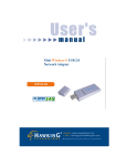
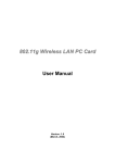
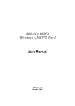
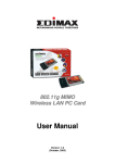
802.11g Hi-Gain Wireless
LAN USB Adapter
User Manual
Version: 1.0
(March, 2004)
COPYRIGHT
Copyright ©2004/2005 by this company. All rights reserved. No part of this
publication may be reproduced, transmitted, transcribed, stored in a retrieval system,
or translated into any language or computer language, in any form or by any means,
electronic, mechanical, magnetic, optical, chemical, manual or otherwise, without the
prior written permission of this company
This company makes no representations or warranties, either expressed or implied,
with respect to the contents hereof and specifically disclaims any warranties,
merchantability or fitness for any particular purpose. Any software described in this
manual is sold or licensed "as is". Should the programs prove defective following their
purchase, the buyer (and not this company, its distributor, or its dealer) assumes the
entire cost of all necessary servicing, repair, and any incidental or consequential
damages resulting from any defect in the software. Further, this company reserves the
right to revise this publication and to make changes from time to time in the contents
hereof without obligation to notify any person of such revision or changes.
All brand and product names mentioned in this manual are trademarks and/or
registered trademarks of their respective holders.
Federal Communication Commission
Interference Statement
This equipment has been tested and found to comply with the limits for a Class B
digital device, pursuant to Part 15 of FCC Rules. These limits are designed to
provide reasonable protection against harmful interference in a residential installation.
This equipment generates, uses, and can radiate radio frequency energy and, if not
installed and used in accordance with the instructions, may cause harmful
interference to radio communications. However, there is no guarantee that
interference will not occur in a particular installation. If this equipment does cause
harmful interference to radio or television reception, which can be determined by
turning the equipment off and on, the user is encouraged to try to correct the
interference by one or more of the following measures:
1. Reorient or relocate the receiving antenna.
2. Increase the separation between the equipment and receiver.
3. Connect the equipment into an outlet on a circuit different from that to which the
receiver is connected.
4. Consult the dealer or an experienced radio technician for help.
FCC Caution
This device and its antenna must not be co-located or operating in conjunction with
any other antenna or transmitter.
This device complies with Part 15 of the FCC Rules. Operation is subject to the
following two conditions: (1) this device may not cause harmful interference, and (2)
this device must accept any interference received, including interference that may
cause undesired operation.
Any changes or modifications not expressly approved by the party responsible for
compliance could void the authority to operate equipment.
Federal Communications Commission (FCC) Radiation Exposure Statement
This equipment complies with FCC radiation exposure set forth for an
uncontrolled environment. In order to avoid the possibility of exceeding the
FCC radio frequency exposure limits, human proximity to the antenna shall not
be less than 2.5cm (1 inch) during normal operation.
Federal Communications Commission (FCC) RF Exposure Requirements
SAR compliance has been established in the laptop computer(s) configurations with
PCMCIA slot on the side near the center, as tested in the application for Certification,
and can be used in laptop computer(s) with substantially similar physical dimensions,
construction, and electrical and RF characteristics. Use in other devices such a PDAs
or lappads is not authorized. This transmitter is restricted for use with the specific
antenna(s) tested in the application for Certification. The antenna(s) used for this
transmitter must not be co-located or operating in conjunction with any other antenna
or transmitter.
R&TTE Compliance Statement
This equipment complies with all the requirements of DIRECTIVE 1999/5/EC OF THE
EUROPEAN PARLIAMENT AND THE COUNCIL of March 9, 1999 on radio
equipment and telecommunication terminal Equipment and the mutual recognition of
their conformity (R&TTE)
The R&TTE Directive repeals and replaces in the directive 98/13/EEC
(Telecommunications Terminal Equipment and Satellite Earth Station Equipment) As
of April 8, 2000.
Safety
This equipment is designed with the utmost care for the safety of those who install and
use it. However, special attention must be paid to the dangers of electric shock and
static electricity when working with electrical equipment. All guidelines of this and of
the computer manufacture must therefore be allowed at all times to ensure the safe
use of the equipment.
EU Countries Intended for Use
The ETSI version of this device is intended for home and office use in Austria,
Belgium, Denmark, Finland, France, Germany, Greece, Ireland, Italy, Luxembourg,
the Netherlands, Portugal, Spain, Sweden, and the United Kingdom.
The ETSI version of this device is also authorized for use in EFTA member states:
Iceland, Liechtenstein, Norway, and Switzerland.
EU Countries Not intended for use
None.
CONTENTS
1 INTRODUCTION ............................................................................. 1
1.1
Features ......................................................................................................................... 1
1.2
Specifications................................................................................................................ 1
1.3
Package Contents .......................................................................................................... 2
2 INSTALLATION PROCEDURE ..................................................... 3
3 CONFIGURATION UTILITY ......................................................... 7
3.1
General.......................................................................................................................... 7
3.1.1 Preference Setting .............................................................................................................. 9
3.1.2 Site Survey..........................................................................................................................9
3.2
Profiles ........................................................................................................................ 10
3.2.1 Configure the Profile ....................................................................................................... 12
3.2.2 Enable WPA..................................................................................................................... 14
3.3
Current Statistics ......................................................................................................... 16
3.4
About........................................................................................................................... 17
4 TROUBLESHOOTING .................................................................. 18
1 Introduction
Thank you for purchasing the 802.11g Hi-Gain Wireless LAN USB Adapter. This adapter complies with IEEE
802.11g standard, which supports up to 54Mbps high-speed wireless network connections. It can also work
with IEEE 802.11b devices. When the card connects to 11b devices, the link speed will be up to 11Mbps.
By integrating with 6dBi Directional Hi-Gain Antenna, this USB Adapter increases the signal strength and the
focus of wireless coverage so that the link quality and communication distance are significantly improved. For
security issues, this adapter supports 64/128-bit WEP data encryption that protects your wireless network
from eavesdropping. It also provides WPA (Wi-Fi Protected Access) feature that combines IEEE 802.1x and
TKIP (Temporal Key Integrity Protocol) technologies. With WPA function, users are required to authorize
before accessing to APs or AP Routers, and the data transmitted in the network is encrypted/decrypted by a
secret key dynamically changed.
This adapter supports USB 2.0 interface, which is forty times than USB 1.1 interface. Through the faster data
transfer interface, this adapter can deliver more data at a time and raise the data transfer rate to 54Mbps.
USB 2.0 is also backward compatible with USB 1.1/1.0 standards, so the adapter can work with PCs or
Laptops that only support USB 1.1/1.0 interface. This card is cost-effective, together with the versatile
features; it is the best solution for you to build your wireless network.
1.1 Features
•
•
•
•
•
•
•
•
Comply with IEEE 802.11g (2.4GHz, OFDM) and IEEE 802.11b standards.
Works with both IEEE 802.11b and IEEE 802.11g products.
High-speed transfer data rate - up to 54Mbps.
High throughput supports multi-media data bandwidth requirement.
Supports 64/128-bit WEP and WPA (TKIP with IEEE 802.1x with) WLAN securities.
Automatic data rate fallback increases data security and reliability.
Supports the most popular operating system: Windows 98SE/Me/2000/XP.
Supports USB 2.0/1.1/1.0 interface.
1.2 Specifications
•
•
•
•
•
Standard: IEEE 802.11b/g
Host Interface: USB 2.0/1.1/1.0
USB Port: Mini-USB
Frequency Band: 2.4000 ~ 2.4835GHz (Industrial Scientific Medical Band)
Modulation: OFDM with BPSK, QPSK, 16QAM, 64QAM (11g)
BPSK, QPSK, CCK (11b)
1
•
•
•
•
•
•
•
•
•
•
•
Data Rate: 54/48/36/24/18/12/11/9/6/5.5/2/1Mbps auto fallback
Security: 64/128-bit WEP Data Encryption, WPA (TKIP with IEEE 802.1x)
Antenna: 6dBi Directional Hi-Gain Antenna
Drivers: Windows 98SE/Me/2000/XP (2000 Service Pack 3 above)
LEDs: Power, Link
Transmit Power: 20dBm
Signal Range: Indoors: Up to 500 ft (150 meters), Outdoors: Up to 2100 ft (650 meters)
Dimension: 120(H) x 75(W) x 87(D) mm
Temperature: 32~131°F (0 ~55°C)
Humidity: Max. 95% (NonCondensing)
Certification: FCC, CE
1.3 Package Contents
Before you begin the installation, please check the items of your package. The package should include the
following items:
•
One USB Adapter
•
One USB 2.0 Extension Cable (150 cm)
•
One Quick Guide
•
One CD (Driver/Utility/User Manual)
If any of the above items is missing, contact your supplier as soon as possible.
2
2 Installation Procedure
Before you proceed with the installation, please notice following descriptions.
Note: The following installation was operated under Windows XP. (Procedures are similar for
Windows 98SE/Me/2000.)
Note: The driver of Windows 2000 can only support Windows 2000 Service Pack 3 above.
I. Install the Driver
A. Insert the Installation CD into your CD-ROM driver.
B. Insert the USB adapter to the USB port of your laptop or desktop PC.
C. Choose the selection “Install from a list or
specific location (Advanced)” and click “Next”.
D. Click “Browse” to search for the driver. Choose
the location to “D:\Driver\xxx” (“D” is where your
CD-ROM Driver, “xxx” is the OS system of your
computer) and click “Next”.
E. A Windows driver warning message appears,
click “Continue Anyway”.
3
F. The wizard will install the driver automatically. Click “Finish” to complete the installation.
II. Install the Utility
A. Execute the "Utility\setup.exe" program from the installation CD.
B. The installShield Wizard box will appear, click “Next” to continue.
D.
C. Choose the selection “I accept the terms in the
license agreement” and click “Next”.
4
Enter your “User Name” and “Organization”
which is only for reference, then click “Next”.
E. If you want to change the destination folder,
click “Change”, or click “Next” to continue.
F. The wizard has installed the driver automatically.
Click “Finish” to complete the installation.
5
III. Using the Utility
Go to Start\All Programs\Envara Configuration Utility and select “Envara Configuration Utility”. You are
able to use the utility.
6
3 Configuration Utility
The Configuration Utility is a powerful application that helps you configure the adapter and monitor the
link status and the statistics during the communication process.
However, there are some restrictions on the utility. Before using the utility, you have to know about
them.
1. If you want to connect to 11g (up to 54Mbps) network, please ensure to install the adapter to PC or
laptop with USB 2.0 interface. This adapter can only support 11b while you connect it to the USB
1.1/1.0 port of your computer.
2. Windows 98SE/Me may not support USB 2.0 interface so that this adapter can only work in 11b
mode in that kind of OS system.
3. This adapter will work in 11b mode when the network type is in Ad Hoc mode. It is defines by Wi-Fi
organization. If you want to enable the data rate up to 54Mbps (11g), please follow steps listed
below.
A. Go to “Network Connections”.
B. Right Click the “Wireless Network Connection” and select “Properties”.
C. From the pop-up screen, click “Configure”.
D. Enter into “Advanced” page of the “Properties” screen.
E. Change the setting of “IBSS Originator Phy-Mode” from “802.11b” to “802.11g”.
3.1
General
From the “General” screen, you can view all the information of the network you are connecting to.
7
Parameter
Description
Connected to (SSID)
Display the wireless network which the adapter is connecting to.
Network Mode
There are two sorts of network types: Infrastructure and Ad Hoc.
This field shows the current network type.
Channel / Frequency
Display the number of the radio channel and the frequency used for
the networking.
Max. Network Rate
This field shows the maximum link rate of the network, that is
54Mbps for 802.11g and 11Mbps for 11b.
Security
Display the security setting of the network. “Disabled” mean no
security settings of the network.
Power Save
This field displays the power save scheme for the adapter (that is
Max performance/Max battery life/Auto).
Active Profile
This field shows the current connection profile.
Radio Status
This field shows the transmitter’s status (On or Off).
Enable Radio Button
This button is used to enable and disable radio transmission.
Link Quality
The number of link quality indicates the quality of the link. The
higher the percentage, the better the quality.
Received
This field shows the current received baud rate (measured in
Kbytes/sec).
Sent
This field shows the current sent baud rate (measured in
Kbytes/sec).
Network Rate
The data rate is changed when the environment is different. This
field can display the current data rate, so that you can adjust the
direction of the adapter or distance from other wireless stations.
Preferences Button
If you want to change the unit of link quality or the update interval
for transmitted and received data, click this button to change the
settings.
8
Parameter
Description
View Site Button
To view the available network nearby, click the “View Site” button.
3.1.1 Preference Setting
This preference screen enables you to change the unit of link quality or the update interval for
transmitted and received data. The default settings is “10” for “Statistics Update Interval” and “Percent”
for “Parameter Display Units”. If you want to set up as default values, click “Defaults”. This preference
setting also enables you to change the “Country Code”. When you are in different country, you can
change the “country code” from here.
3.1.2 Site Survey
This screen shows all wireless networks nearby. If you want to connect to any network on the list,
double-click the item on the list or click “Connect”, and the adapter will automatically connect to the
selected network.
9
Parameter
Description
Available Networks/AP’s List
In the list, you can know the information of wireless networks
including Link Quality, Network Name, Mode, Security, etc. This
information will help you to decide which network you want to
connect.
Connect Button
Select one of the networks from the list and click “Connect”, the
adapter will connect to the network automatically. You can also
right click the network and select “Connect”.
Save Profile Button
Save the selected network to be a profile. This profile will be listed
in the profiles list table so that you can easy to connect to the
network without from “Site Survey” screen. You can also right click
the network and select “Save as Profile”.
Edit Connect Button
If the connection network has changed the WEP security setting,
you can click this button to update the setting of the adapter. Note
that the WEP setting has to be the same with the network. You can
also right click the connection network and select “Edit Connect”.
Rescan Button
Click “Rescan” button to collect the associated information of all the
wireless networks nearby.
AP View/Network View Button
This switch button can change the way to display the available
networks. “Network View” displays the network information simply.
3.2
Profiles
You can manage the connection list from profiles list. It is very convenience for you to connect to one of
the networks quickly.
10
Parameter
Description
Auto-Selection Profiles
If a profile is set as an Auto-Selection profile it is used to attempt to
automatically connect the adapter to the respective profile in the
order of the appearance at startup. The networks ever been
connected by the adapter will display in the profile list. If you want
to connect to one of the profiles in the list, double-click the item on
the list or right click the network and select “Connect”.
Additional Profiles
You can create additional profiles here as other selections. The
adapter will not connect to the additional profiles in the list
automatically. If you want to change the connection to one of the
profiles, double-click the profile or select the profile and click
“Connect”. You can click “New” and “Edit” to configure the profile
list.
Right Click Function List
Add – Add a new profile in the list.
Edit – Edit the selected profile.
Duplicate – Copy the same profile to the list.
Delete – Delete the selected profile.
Connect – Connect to the profile.
Add/Remove to/from Auto-Selection – Add the profile to the
“Auto-Selection Profiles” or remove it from “Auto-Selection Profiles”
to “Additional Profiles”.
Export Profile – Save the profile as a new file.
Import Profiles – Import the profile file to the list.
Export All Profiles – Save all the profiles as a new file.
11
3.2.1 Configure the Profile
When you click “New” or “Edit”, the “Profile Configuration” screen will be popped up. In the screen,
there are two pages including General and Security.
General
Parameter
Description
Name
To name a recognizable profile name for you to identify the different
networks.
Network Name (SSID)
The SSID (up to 32 printable ASCII characters) is the unique name
identified in a WLAN. The ID prevents the unintentional merging of
two co-located WLANs.
You may specify a SSID for the adapter and then only the device
with the same SSID can interconnect to the adapter.
Network Mode
Infrastructure – This operation mode requires the presence of an
802.11 Access Point. All communication is done via the Access
Point.
Ad-Hoc – Select this mode if you want to connect to another
wireless stations in the Wireless LAN network without through an
Access Point.
Power Save
Enable the adapter in the power saving when it is idle.
12
Parameter
Description
Channel / Frequency
This setting is only available for Ad Hoc mode. The channel setting
should be the same with the network you are connecting to.
Auto-Select Profile Member
If you select the check box, this profile will be put in the
“Auto-Selection Profiles” list.
Defaults
The default values are Ad Hoc mode and channel one. If you want
to set up to default, click this button.
Encryption
Parameter
Description
Security
None – Disable the WEP Data Encryption.
WEP – Enable the WEP Data Encryption. When the item is
selected, you have to continue setting the WEP Key Length and the
encryption keys.
Use 802.1x
This function is not activated yet. It will not implement if you enable
it.
13
Parameter
Description
Encryption Key
(Key1 ~ Key4)
Select the default encryption key from Key 1 to Key 4 by selected
the radio button. The WEP keys are used to encrypt data
transmitted in the wireless network. Fill the text box by following the
rules below.
64-bit – Input 10-digit Hex values (in the “A-F”, “a-f” and “0-9”
range) as the encryption keys. For example: “0123456aef“.
128-bit – Input 26-digit Hex values (in the “A-F”, “a-f” and “0-9”
range) as the encryption keys. For example:
“01234567890123456789abcdef“.
3.2.2 Enable WPA
Wi-Fi Protected Access (WPA) is a specification of standards-based, interoperable security
enhancements that strongly increase the level of data protection (encryption) and access control
(authentication) for existing and future wireless LAN systems. The technical components of WPA
include Temporal Key Integrity Protocol (TKIP) for dynamic key exchange, and 802.1x for
authentication.
WPA function is enabled in the following software system:
1. Windows XP Service Pack 1 with Windows XP Support Patch for Wi-Fi Protected Access program
in addition.
2. Configure the card by Wireless built-in utility (Wireless Zero Configuration).
1.
2.
From here, right click the icon to
select “View Available Wireless
Networks”.
Click “Advanced” from
“Wireless Network Connection”.
14
3.
Click “Configure” to configure the WPA
function for the current network.
Parameter
Description
Network Authentication
Open –No authentication is needed among the wireless network.
Shared – Only wireless stations using a shared key (WEP Key
identified) are allowed to connecting each other.
WPA – This mode is for enterprise with an authentication server
(Radius Server), WPA-enabled access point, and a WPA-enabled
client. Once WPA is enabled, all clients and access points on the
network must be WPA-enabled in order to access the network.
WPA-PSK – It is a special mode designed for home and small
business users who do not have access to network authentication
servers. In this mode, known as Pre-Shared Key, the user manually
enters the starting password in their access point or gateway, as
well as in each PC on the wireless network. WPA takes over
automatically from that point, keeping unauthorized users that don't
have the matching password from joining the network, while
encrypting the data traveling between authorized devices.
15
Parameter
Description
Data Encryption
WEP – In WPA or WPA-PSK mode, WEP is also able to be the
encryption method for the transmission data.
TKIP – TKIP (Temporal Key Integrity Protocol) changes the
temporal key every 10,000 packets (a packet is a kind of message
transmitted over a network.) This insures much greater security
than the standard WEP security.
Note: All devices in the network should use the same encryption
method to ensure the communication.
3.3
Current Statistics
This option enables you to view the sign strength and the statistic information of successful Tx and Rx
baud rate. You may reset the counters by clicking “Reset”. The “SNR” indicates the rate of noise and
signal in the environment, the bigger of the value, the better of the signal strength.
16
3.4
About
By choosing this option, you can view basic information such as the Driver, Firmware and Utility
Version. And you can click the hyperlink to connect the website for the information of the wireless
chipset vendor.
17
4 Troubleshooting
This chapter provides solutions to problems usually encountered during the installation and operation
of the adapter.
1. Why can’t the USB adapter work or only work in 11b mode while connect to USB 2.0 port?
If this situation occurs, please upgrade the driver of your USB port. This problem may be the
compatibility issue with the old driver of the USB port.
2. What is the IEEE 802.11g standard?
802.11g is the new IEEE standard for high-speed wireless LAN communications that provides for
up to 54 Mbps data rate in the 2.4 GHz band. 802.11g is quickly becoming the next mainstream
wireless LAN technology for the home, office and public networks.
802.11g defines the use of the same OFDM modulation technique specified in IEEE 802.11a for
the 5 GHz frequency band and applies it in the same 2.4 GHz frequency band as IEEE 802.11b.
The 802.11g standard requires backward compatibility with 802.11b.
The standard specifically calls for:
A. A new physical layer for the 802.11 Medium Access Control (MAC) in the 2.4 GHz frequency
band, known as the extended rate PHY (ERP). The ERP adds OFDM as a mandatory new
coding scheme for 6, 12 and 24 Mbps (mandatory speeds), and 18, 36, 48 and 54 Mbps
(optional speeds). The ERP includes the modulation schemes found in 802.11b including
CCK for 11 and 5.5 Mbps and Barker code modulation for 2 and 1 Mbps.
B. A protection mechanism called RTS/CTS that governs how 802.11g devices and 802.11b
devices interoperate.
3. What is the IEEE 802.11b standard?
The IEEE 802.11b Wireless LAN standard subcommittee, which formulates the standard for the
industry. The objective is to enable wireless LAN hardware from different manufactures to
communicate.
4. What does IEEE 802.11 feature support?
The product supports the following IEEE 802.11 functions:
CSMA/CA plus Acknowledge Protocol
Multi-Channel Roaming
Automatic Rate Selection
RTS/CTS Feature
Fragmentation
Power Management
5. What is Ad-hoc?
An Ad-hoc integrated wireless LAN is a group of computers, each has a Wireless LAN adapter,
Connected as an independent wireless LAN. Ad hoc wireless LAN is applicable at a
departmental scale for a branch or SOHO operation.
18
6. What is Infrastructure?
An integrated wireless and wireless and wired LAN is called an Infrastructure configuration.
Infrastructure is applicable to enterprise scale for wireless access to central database, or
wireless application for mobile workers.
7. What is BSS ID?
A specific Ad hoc LAN is called a Basic Service Set (BSS). Computers in a BSS must be
configured with the same BSS ID.
8. What is WEP?
WEP is Wired Equivalent Privacy, a data privacy mechanism based on a 40 bit shared key
algorithm, as described in the IEEE 802 .11 standard.
9. What is TKIP?
TKIP is a quick-fix method to quickly overcome the inherent weaknesses in WEP security,
especially the reuse of encryption keys. TKIP is involved in the IEEE 802.11i WLAN security
standard, and the specification might be officially released by early 2003.
10. What is AES?
AES (Advanced Encryption Standard), a chip-based security, has been developed to ensure the
highest degree of security and authenticity for digital information, wherever and however
communicated or stored, while making more efficient use of hardware and/or software than
previous encryption standards. It is also included in IEEE 802.11i standard. Compare with AES,
TKIP is a temporary protocol for replacing WEP security until manufacturers implement AES at
the hardware level.
11. Can Wireless products support printer sharing?
Wireless products perform the same function as LAN products. Therefore, Wireless products can
work with Netware, Windows 2000, or other LAN operating systems to support printer or file
sharing.
12. Would the information be intercepted while transmitting on air?
WLAN features two-fold protection in security. On the hardware side, as with Direct Sequence
Spread Spectrum technology, it has the inherent security feature of scrambling. On the software
side, WLAN series offer the encryption function (WEP) to enhance security and Access Control.
Users can set it up depending upon their needs.
19
13. What is DSSS?What is FHSS?And what are their differences?
Frequency-hopping spread-spectrum (FHSS) uses a narrowband carrier that changes frequency
in a pattern that is known to both transmitter and receiver. Properly synchronized, the net effect
is to maintain a single logical channel. To an unintended receiver, FHSS appears to be
short-duration impulse noise. Direct-sequence spread-spectrum (DSSS) generates a redundant
bit pattern for each bit to be transmitted. This bit pattern is called a chip (or chipping code). The
longer the chip is, the greater the probability that the original data can be recovered. Even if one
or more bits in the chip are damaged during transmission, statistical techniques embedded in the
radio can recover the original data without-the need for retransmission. To an unintended
receiver, DSSS appears as low power wideband noise and is rejected (ignored) by most
narrowband receivers.
14. What is Spread Spectrum?
Spread Spectrum technology is a wideband radio frequency technique developed by the military
for use in reliable, secure, mission-critical communication systems. It is designed to trade off
bandwidth efficiency for reliability, integrity, and security. In other words, more bandwidth is
consumed than in the case of narrowband transmission, but the trade off produces a signal that
is, in effect, louder and thus easier to detect, provided that the receiver knows the parameters of
the spread-spectrum signal being broadcast. If a receiver is not tuned to the right frequency, a
spread –spectrum signal looks like background noise. There are two main alternatives, Direct
Sequence Spread Spectrum (DSSS) and Frequency Hopping Spread Spectrum (FHSS).
20