1
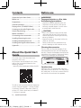
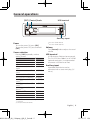
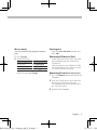
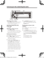
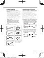
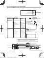
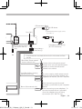
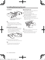
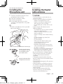
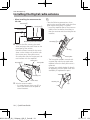
KDC-BT73DAB
KDC-BT53U
KDC-5057SD
CD-RECEIVER
Quick Start Guide
© 2012 JVC KENWOOD Corporation
B59-2186-00_00_13Stepup_QSG_E_En.indd 1
B59-2186-00/00 (E)
12/12/17 15:0
Contents
Before use
About the Quick Start Guide.......................... 2
# WARNING
To prevent injuries or a fire, take
the following precautions:
Before use.............................................................. 2
Preparations.......................................................... 4
General operations............................................. 5
Playing music (CD/USB/SD/iPod).................. 6
Listening to the radio/Digital radio.............. 8
• Stop the car before operating the unit.
• To prevent a short circuit, never put or
leave any metallic objects (such as coins
or metal tools) inside the unit.
Appendix..............................................................19
! CAUTION
• Adjust the volume so that you can hear
sound outside the car. Driving with the
volume adjusted to a too high level may
cause an accident.
• Wipe off the dirt on the panel with a dry
silicon or soft cloth.
Failure to observe this precaution may
result in damage to the monitor or unit.
About the Quick Start
Guide
The unit may not function properly if the
connector between the unit and faceplate
are dirty. Detach the faceplate and clean the
connector with a cotton swab gently, being
careful not to damage the connector.
Hands-free phoning........................................... 9
Before installation.............................................10
Connecting wires to terminals.....................12
Installing/Removing the unit........................14
Installing the Microphone unit ...................15
Installing the Digital radio antenna...........15
This Quick Start Guide describes basic
functions of this unit.
For functions not described in this Guide,
refer to the Instruction Manual on the
following website:
manual2.jvckenwood.com/edition/im362/
Cleaning the connector
Connector
Condensation
When the car is air-conditioned, moisture
may collect on the laser lens. This may cause
disc read errors. In this case, remove the disc
and wait for the moisture to evaporate.
To refer to the Instruction Manual, a browser
such as Internet Explorer® 7 or later, Firefox®
3.6 or later, Chrome™ 20 or later, Safari® 5.1
or later, iOS Safari® 4.0 or later, or Android™
2.2 or later is required.
2 | Quick Start Guide
B59-2186-00_00_13Stepup_QSG_E_En.indd 2
12/12/17 15:0
Notes
• If you experience problems during
installation, consult your Kenwood dealer.
• When you purchase optional accessories,
check with your Kenwood dealer to make
sure that they can work with your model
and in your area.
• Characters that conform to ISO 8859-1
can be displayed.
• Characters that conform to ISO 8859-5
or ISO 8859-1 can be displayed. Refer
to “Russian” of <12-7. Initial settings>
(Instruction Manual).
• The Radio Data System feature won’t work
where the service is not supported by any
broadcasting station.
• USB rating is indicated on the main unit
under the detachable faceplate.
About the discs used with this unit
• This unit can only play the CDs with
Handling discs
• Do not touch the recording surface of
the disc.
• Do not stick tape etc. on the disc, or use a
disc with tape stuck on it.
• Do not use any accessories for the disc.
• Do not use any solvents to clean discs.
Use a dry silicon or soft cloth.
• Clean the disc by moving the cloth
outward from the center of the disc.
• When removing a disc from this unit, pull
it out horizontally.
• If the center hole or outside rim of a disc
has burrs, remove them before inserting
a disc.
How to reset your unit
If the unit fails to operate properly, press the
Reset button. The unit returns to the factory
settings.
Reset button
.
• The following discs cannot be used:
-- A disc that is not round
-- A disc with coloring on the recording
surface or a disc that is dirty
-- A recordable/rewritable disc that has
not been finalized (For the finalization
process, refer to the instruction manual
that came with your disc writing
software or your disc recorder.)
-- An 8 cm (3 inch) disc (An attempt
to insert using an adapter can cause
malfunction.)
B59-2186-00_00_13Stepup_QSG_E_En.indd 3
The illustrations of the display and panel appearing
in this manual are examples used to explain more
clearly how the controls are used. Therefore, what
appears on the display in the illustrations may differ
from what appears on the display on the actual
equipment, and some of the images on the display
may be inapplicable.
English | 3
12/12/17 15:0
Preparations
[Control] knob (Volume knob)
Release
Canceling the Demonstration
mode
Detaching/ Attaching the faceplate
Cancel the Demonstration mode when
you use the unit for the first time after
installation.
1
Press [Control] knob to cancel the
Demonstration mode when the message
“To cancel DEMO Press the volume knob”
appears (approx. 15 seconds).
Press the
Release button.
2 Turn [Control] knob to select “YES”, and
then press [Control] knob.
The Demonstration mode can also be
canceled in the Function Setting mode.
Refer to <12-6. Demonstration mode
setting> in Instruction manual
!
• Remove the faceplate at once after
pressing the Release button; otherwise it
can fall down due to vibration.
• The faceplate is a precision component of
the unit and can be damaged by shocks
or jolts.
• Keep the faceplate in its case while
detached.
• Do not place the faceplate (and case) in
areas exposed to direct sunlight, excessive
heat or humidity. Also avoid places with
too much dust or the possibility of water
splashing.
4 | Quick Start Guide
B59-2186-00_00_13Stepup_QSG_E_En.indd 4
12/12/17 15:0
General operations
USB terminal
[SRC] [Control] knob
Auxiliary input
Power
To turn the power ON, press [SRC].
To turn the power OFF, press and hold
[SRC].
Source selection
Pressing [SRC] repeatedly switches
among sources.
Source
Display
Standby
“STANDBY”
Digital radio[2]
“DIGITAL RADIO”
Tuner
“TUNER”
USB device connected to front USB
“USB (FRONT)”
terminal
USB device connected to rear USB
“USB (REAR)”
terminal
[1]
iPod connected to front USB terminal “iPod (FRONT)”
iPod connected to rear USB terminal[1] “iPod (REAR)”
aha™ of iPod connected to front USB “aha (FRONT)”
terminal[1][2][3]
aha™ of iPod connected to rear USB “aha (REAR)”
terminal[1][2][3]
aha™ of device connected via
“aha”
Bluetooth[1][2][3]
Bluetooth audio[2] [3]
“BT AUDIO”
SD[1] [4]
“SD”
CD[1]
“CD”
Auxiliary Input
“AUX”
[3]
[4]
Function of KDC-BT53U.
Function of KDC-5057SD.
Volume
Turn [Control] knob to adjust the sound
volume.
USB terminal
A USB device or iPod can be connected.
The CA-U1EX (Max. 500mA) or KCA‑iP102
(optional accessories) is recommended
to connect a USB device or iPod.
Auxiliary input
A portable audio device can be
connected with a stereo mini-plug (3.5
mm ø).
This source can be selected only when it can
be played.
Function of KDC-BT73DAB.
[1]
[2]
B59-2186-00_00_13Stepup_QSG_E_En.indd 5
English | 5
12/12/17 15:0
Playing music (CD/USB/SD/iPod)
Disc slot
CA-U1EX[1]
[G]
[SRC] [Control] knob
Disc slot cover
KCA-iP102[1]
[1/6] Release
[E/F] [R/S] REAR USB indicator USB Terminal
Playing a disc
Open the Disc slot cover upward.
Insert a disc in the Disc slot.
When it is inserted, the source is
switched automatically and playback
starts.
Close the Disc slot cover.
Playing a USB device/ iPod
Connect a USB device or iPod to the USB
terminal as shown above.
When it is connected, the source is
switched automatically and playback
starts.
You can connect the iPod or USB device
to either one of the USB terminals
provided at the front and rear of this unit.
If you connect it to the rear USB terminal,
the “REAR USB” indicator stays lit.
optional accessories
[1]
Playing SD card (KDC-5057SD only)
1
Press the Release button and detach the
Faceplate.
2 Hold the SD card as shown below and
insert it into the SD card slot until it
clicks.
SD card (commercially available)
3 Reattaching the Faceplate.
4 Press [SRC] to select “SD” source.
Selecting an audio file folder
Press [R] or [S].
Selecting a song (track or file)
Press [E] or [F].
Fast-forwarding or fastbackwarding a song (track or file)
Press and hold [E] or [F].
Pause and play a song (track or
file)
Press and hold [1/6].
6 | Quick Start Guide
B59-2186-00_00_13Stepup_QSG_E_En.indd 6
12/12/17 15:0
Music search
Ejecting disc
1 Press [1/6].
2 Search for a song.
Removing USB device/ iPod
You can search for the song you want to
play.
Operation type
Operation
Selecting items
Turn [Control] knob.
Determining selection
Press [Control] knob.
Returning to previous item Press [1/6].
To cancel music search in audio files or
iPod, Press and hold [1/6].
B59-2186-00_00_13Stepup_QSG_E_En.indd 7
Open the Disc slot cover upward, and
press [G].
Switch to a source other than USB, iPod,
and Aha Radio, and then remove the
USB device.
Data contained in the USB device/ iPod
may be damaged if you remove it when
it is used as the active source.
Removing SD card (KDC-5057SD only)
1
Press the Release button and detach the
Faceplate.
2 Push the SD card until it clicks and then
remove your finger from the card.
The card pops up so that you can pull it
out with your fingers.
3 Attaching the Faceplate.
English | 7
12/12/17 15:0
Listening to the radio/Digital radio
[SRC] [Control] knob
[1/6]
[R]
[E/F]
Selecting a tuner source
4 Turn [Control] knob to select preset
Selecting a band (FM or AM)
(Tuner only)
Recalling the stations in the
memory
Press [SRC] to select “TUNER” or “DIGITAL
RADIO” (KDC-BT73DAB only). Refer to
<Source selection> (page 5).
Press [R].
Selecting a station/ service
Press [E] or [F].
The seek mode can be changed. Refer
to <9-5. Tuner setting> or <10-9. Digital
Radio setting>in Instruction manual
Station preset memory
1 Press [R] to select a band. (Tuner only)
2 Press [E] or [F] to select the
station/ service you want to save in the
station preset memory.
number (FM/ Digital Radio: “1” – “18”,
AM: “1” – “6”), and then press and hold
[Control] knob.
1 Press [R] to select a band. (Tuner only)
2 Press [1/6].
3 Turn [Control] knob to select a preset
number (FM/ Digital Radio: “1” – “18”, AM:
“1” – “6”), and then press [Control] knob.
In the Mix Station preset mode, band
names of tuner sources are displayed as
follows:
FM: FM broadcast station
AM: AM broadcast station
DR: Digital Radio service
3 “TUNER”: Press [1/6].
“DIGITAL RADIO”: Press [1/6] twice.
Press [1/6] again to enter the Mix
Station preset mode. In this mode,
different bands and tuner sources (FM,
AM, Digital Radio etc.) can be saved
in the same preset layer, which allows
you to recall a desired station without
switching between bands and/or tuner
sources. Maximum of 6 stations can be
preset in the Mix Station preset mode.
8 | Quick Start Guide
B59-2186-00_00_13Stepup_QSG_E_En.indd 8
12/12/17 15:0
Function of KDC-BT73DAB, KDC-BT53U
Hands-free phoning
[Control] knob
[Ú]
Pairing a Bluetooth device
You can pairing your Bluetooth device in
this unit.
1
Operate the Bluetooth device to request
this unit for connection.
The name of this unit (“KDC-####”)
appears on the Bluetooth device.
“Press the volume knob” appears.
2 Press [Control] knob.
Connection to your Bluetooth device
starts, “Pairing Success” appears a while
later, and then the previous source is
selected.
When registration of your cell phone is
completed, the phone book of the cell
phone is automatically downloaded
to this unit. (If the phone book has not
been downloaded to this unit, operate
the cell phone to download it.)
B59-2186-00_00_13Stepup_QSG_E_En.indd 9
Dialing a number in the phone
book
Dial the phone number in the phone book
of your cell phone.
If the phone book has not been
downloaded to this unit, operate the cell
phone to download it.
1 Press [Ú].
2 Turn [Control] knob to select “Phone
Book”, and then press [Control] knob.
3 Turn [Control] knob to select a name,
and then press [Control] knob.
4 Turn [Control] knob to select a phone
number.
5 Press [Ú].
Answering a phone call
Press [Ú].
Disconnecting a call
Press [Ú].
English | 9
12/12/17 15:0
Before installation
# WARNING
• The unit can only be installed in a car with
a 12V DC power supply, negative ground.
• If you connect the ignition wire (red)
and the battery wire (yellow) to the car
chassis (ground), you may cause a short
circuit, that in turn may start a fire. Always
connect those wires to the power source
running through the fuse box.
! CAUTION
• Use the power harness enclosed with this
unit for connecting power. Using a power
harness enclosed with other models can
cause malfunction.
• Install this unit in the console of your
vehicle.
• Do not touch the metal parts of this unit
during and shortly after use of the unit.
Metal parts such as the heat sink and
enclosure become hot.
• Mounting and wiring this product
requires skills and experience. For safety’s
sake, leave the mounting and wiring work
to professionals.
• If you experience any problem during
installation, consult your Kenwood dealer.
• Disconnect the battery’s negative terminal
before installing the unit.
• Insulate unconnected wires with vinyl
tape or other similar materials. To prevent
a short circuit, do not remove the caps on
the ends of the unconnected wires and
terminals.
• Be sure to ground this unit to the car’s
chassis again after mounting.
• If the fuse blows, first make sure the wires
are not touching other parts to cause a
short circuit, and then replace the old fuse
with one with a new the same rating.
• When connecting only two speakers,
connect the connectors either to both
of the front output terminals or to both
of the rear output terminals (do not mix
front and rear terminals). For example, if
you connect the + connector of the left
speaker to a front output terminal, do
•
•
•
•
•
•
•
not connect the - connector to a rear
output terminal.
Connect the speaker wires correctly to the
corresponding terminals. The unit may
be damaged or fail to work if you share
the - wires or ground them to any metal
part in the car.
Do not use your own screws. Use only
the supplied screws. Using wrong screws,
could damage the unit.
If your car’s ignition key switch does
not have an ACC position, connect the
ignition wires to a power source that can
be turned on and off with the ignition
key. If you connect the ignition wires to
a constant-voltage power source, as with
battery wires, the battery may die.
If the console has a lid, make sure to
install the unit so that the faceplate will
not hit the lid when it is closed or opened.
After the installing the unit, check
whether the brake lamps, blinkers, wipers,
etc. on the car are working properly.
Mount the unit so that the mounting
angle is 30° or less.
Reception may become poor if there are
metal objects near the Bluetooth antenna.
(KDC-BT73DAB, KDC-BT53U only)
Bluetooth antenna unit
KDC-BT73DAB • This unit has the cooling fan to decrease
the internal temperature. Do not mount
the unit in a place where the cooling
fan of the unit are blocked. Blocking
these openings will inhibit the cooling
of the internal temperature and result in
malfunction.
Cooling fan
10 | Quick Start Guide
B59-2186-00_00_13Stepup_QSG_E_En.indd 10
12/12/17 15:0
Connecting the ISO Connector
For Good Reception
To assure good reception, note the
following:
• Communicate with the cell phone within
the line-of-sight distance of 10 m (30
ft). The communication range becomes
shorter depending on the surrounding
environment. The communication
range also becomes shorter when there
is an obstacle between this unit and
the cell phone. The above maximum
communication range (10 m) is not
always assured.
• A broadcast station or walkie-talkie
located nearby can interfere with
communication due to a too strong
signal.
Installation accessories
1
2
Ignition cable
(Red)
Unit
5[1]
.....1
The pin arrangement for the ISO connectors
depends on the type of vehicle you drive.
Make sure to make the proper connections
to prevent damage to the unit.
The default connection for the wiring
harness is described in 1 below. If the ISO
connector pins are set as described in 2,
make the connection as illustrated.
Please be sure to reconnect the cable as
shown 2 below to install this unit to the
Volkswagen vehicles etc.
1When the A-7 pin (red) is connected with
the ignition, and the A-4 pin (yellow) is
connected to the constant power supply
of the vehicle’s ISO connector (default):
Battery cable
(Yellow)
.....1
6[1]
.....3
.....1 (3m)
Unit
Battery cable
(Yellow)
7[1]
3[1][2]
Vehicle
A-4 Pin
(Yellow)
2When the A-7 pin (red) is connected
to the constant power supply, and the
A-4 pin (yellow) is connected with the
ignition of the vehicle’s ISO connector:
Ignition cable
(Red)
.....2
A-7 Pin
(Red)
A-7 Pin
(Red)
Vehicle
A-4 Pin
(Yellow)
.....1
KDC-BT73DAB only
KDC-BT53U only
[1]
4[1]
[2]
.....1
B59-2186-00_00_13Stepup_QSG_E_En.indd 11
English | 11
12/12/17 15:0
Rear output
Front output
R
Subwoofer output
L
SW FRONT REAR
Connecting wires to terminals
Connector Function Guide
Pin Numbers for
ISO Connectors
External Power
Connector
A-4
A-5
A-6
A-7
A-8
Cable Colour
Functions
Yellow
Blue/White
Orange/White
Red
Black
Battery
Power Control
Dimmer
Ignition (ACC)
Earth (Ground)
Connection
Speaker
Connector
B-1
B-2
B-3
B-4
B-5
B-6
B-7
B-8
Purple
Purple/Black
Gray
Gray/Black
White
White/Black
Green
Green/Black
Rear Right (+)
Rear Right (–)
Front Right (+)
Front Right (–)
Front Left (+)
Front Left (–)
Rear Left (+)
Rear Left (–)
FM/AM antenna input (JASO)
(KDC-BT73DAB, KDC-BT53U only)
R
Digital radio antenna
(Accessory5)
(KDC-BT73DAB only)
Microphone (Accessory3)
(KDC-BT53U only)
⁄
• Speaker Impedance:
4–8Ω
⁄ See <Connecting the ISO Connector> (page 11).
Connector A
8
7
6
5
4
3
2
1
Connector B
8
7
6
5
4
3
2
1
Red (A–7 Pin)
Red (Ignition wire)
Yellow (A–4 Pin)
Yellow (Battery wire)
KDC-BT73DAB only
12 | Quick Start Guide
B59-2186-00_00_13Stepup_QSG_E_En.indd 12
12/12/17 15:0
(JASO)
53U only)
USB connector (0.8m)
To USB device.
USB maximum power supply current : DC 5 V = 1 A
Fuse (10A)
R
L
FM/AM antenna input
(JASO)(KDC-5057SD
only)
Wiring harness
(Accessory1)
Microphone (Accessory3)
(KDC-BT73DAB only)
If no connections are made, do not let the wire come out from
the tab.
Blue/White (Power control/
Antenna control wire)
P.CONT
ANT.
CONT
Light Blue/Yellow (Steering
remote control wire)
REMOTE CONT
STEERING WHEEL
REMOTE INPUT
wire)
y wire)
Brown (Mute control wire)
B59-2186-00_00_13Stepup_QSG_E_En.indd 13
MUTE
Connect either to the power control
terminal when using the optional power
amplifier, or to the antenna control
terminal in the vehicle.
To use the steering wheel remote control
feature, an exclusive remote adapter (not
supplied) that matches your car is required.
When connecting to the Kenwood
navigation system: Refer to your navigation
manual.
When connecting to a car telephone: To
connect the terminal that is grounded
when the telephone rings or during
conversation. (KDC-5057SD only)
English | 13
12/12/17 15:0
Installing/Removing the unit
Installation
Removing the unit
1
Bend the tabs of the mounting sleeve
with a screwdriver or the like and
attach it in place.
<
Remove the trim plate with reference to
<Removing the trim plate>.
2 Remove the faceplate.
3 Insert the two extraction keys
(Accessory2) deeply into the slots on
both sides as shown.
4 Lower the extraction key toward the
bottom, and then pull out the unit
halfway while pressing the extraction key
towards the inside.
Accessory2
• Make sure that the unit is installed
securely in place. If the unit is unstable, it
may malfunction (for example, the sound
may skip).
Removing the trim plate
1
Engage the catch pins on the extraction
key (Accessory2) and release the two
locks on the upper part of frame.
Lift up and pull the frame forward as
shown in the figure.
Lock
!
• Be careful to avoid injury from the catch
pins on the extraction key.
5 Pull the unit all the way out with your
hands, being careful not to drop it.
Catch
Accessory2
2 When the upper part of frame is
removed, remove the lower part of frame.
<
• The frame can be removed from the
bottom side in the same manner.
14 | Quick Start Guide
B59-2186-00_00_13Stepup_QSG_E_En.indd 14
12/12/17 15:0
KDC-BT73DAB, KDC-BT53U only
KDC-BT73DAB only
Installing the
Microphone unit
Installing the Digital
radio antenna
1
! CAUTION
• This film antenna is exclusively for use
inside the vehicle.
• Do not install at the following locations:
-- Where it may block driver’s view
-- Where it may obstruct operation of
safety devices such as air bags
-- On movable glass surface such as rear
hatch
• Signal strength will decrease at the
following locations:
-- On IR reflecting glass or where covered
with mirror type glass film -- Where it overlaps with genuine radio
antenna (pattern)
-- Where it overlaps with window heating
wires
-- At side of vehicle (e.g. door, front
quarter window)
-- On rear window
-- When glass that blocks radio signals
(e.g. IR reflecting glass, thermal
insulation glass) is used
-- Reception may decrease due to noise
when windshield wiper, air conditioner,
or motor is turned on.
-- Reception may decrease depending on
the direction of the broadcast station
with respect to the vehicle (antenna).
• Be sure to check the installation location
of film antenna (Accessory 4) before
installing. Film antenna cannot be
re-pasted.
• Thoroughly wipe oil and dirt from the
pasting surface with the included cleaner
(Accessory 7).
• Do not bend or damage the film antenna
(Accessory 4).
• Warm the pasting surface by turning on
the heater for example, before applying.
• It may not be possible to install on some
type of vehicle.
• Check the cable routing of the film
antenna (Accessory 4) and amplifier
(Accessory 5) before pasting.
Check the installation position of the
microphone (Accessory 3).
2 Clean the installation surface.
3 Install the microphone.
4 Lay the cable up to the unit with it
secured at several positions using tape
or the like.
<
• Install the microphone as far as possible
from the cell phone.
Accessory3
Fix the cable with a commercial item of tape.
Remove the separator of
the microphone, and stick
the microphone to the
place shown above.
Adjust the direction of the
microphone to the driver.
B59-2186-00_00_13Stepup_QSG_E_En.indd 15
English | 15
12/12/17 15:0
KDC-BT73DAB only
Installing the Digital radio antenna
Installation overview
Accessory45
Determining the antenna
installation location
• When installing the antenna on the
left side
Front pillar
150 mm
Earth sheet
Antenna cable (3.5 m)
70 mm*
• The antenna should be installed on the
passenger side for safety.
• Use cord clamper (Accessory 6) to
secure the antenna to the pillar at several
locations.
• The direction of the antenna film
(Accessory 4) changes depending on
whether the film antenna is installed on
the right side or left side.
• Separate the antenna film (Accessory 4)
from the ceramic line (black part) at the
top of the front glass by 150 mm.
Also, place it about 70 mm inside the
ceramic line at the side end of the front
glass. (where the earth sheet of the
amplifier can be pasted on the metal part
of the front pillar)
• Separate from other antennas by at least
100 mm.
• Do not paste the amplifier (Accessory 5)
on the ceramic line (black part) around
the front glass. Because there is not
enough adhesion.
Accessory4
Accessory5
• When installing the antenna on the
right side
Accessory5
Front pillar
Earth sheet
150 mm
Accessory4
70 mm*
*Where the earth sheet of amplifier unit
(Accessory 5) can be pasted on the metal
part of the front pillar.
16 | Quick Start Guide
B59-2186-00_00_13Stepup_QSG_E_En.indd 16
12/12/17 15:0
Antenna Installation
1 Check the installation location.
2 Clean the area where antenna film
3
(Accessory 4), amplifier unit (Accessory
5), and earth sheet are pasted with the
included cleaner (Accessory 7).
The coating on the metal surface need
not be removed.
• Wait until the glass surface is
completely dry before pasting.
• If the glass surface is cold, such as
during winter, warm it with defroster or
dryer.
Remove the separator (tag I) of antenna
film horizontally and paste the antenna
on the front glass.
5 After pasting, rub the element in the
glass surface in the direction of the arrow
shown in the figure to bond it.
6 Remove the application film (tag III).
• Do not touch the feeder terminal of
the element. Also, do not apply any
glass cleaner.
Feeder terminal
7 Match the protrusion of the amplifier
• Remove the separator gently.
• Do not touch the pasting surface
(adhesive side) of the antenna film.
4 Remove the separator (tag II) of antenna
film vertically and paste the antenna
gently while applying pressure.
B59-2186-00_00_13Stepup_QSG_E_En.indd 17
with the 5 on the antenna film and
paste.
• Do not touch the feeder terminal or
the pasting surface (adhesive side) of
the amplifier.
• When installing the antenna on the
right side
Match the protrusion with 5
Earth sheet
Accessory4
Accessory5
English | 17
12/12/17 15:0
KDC-BT73DAB only
Installing the Digital radio antenna
• When installing the antenna on the
left side
Accessory5
Accessory4
Earth sheet
Match the protrusion with 5
8
Remove the film covering the earth
sheet and paste the earth sheet on the
metal part of the vehicle.
Provide sufficient leeway for the earth
sheet so that it does not interfere with
the interior parts (front pillar cover). Also take care that the interior parts do
not interfere with the amplifier.
Accessory5
Front glass
Front pillar
<
• Take the following precautions when
passing the antenna cable inside the front
pillar where the air bag is installed.
-- Install the amplifier part of the antenna
cable in front or above the air bag so
that the antenna and the air bag do not
interfere.
Accessory5
Air bag
Front pillar
-- The front pillar cover is secured with
a special clip which may need to be
replaced when the front pillar cover is
removed.
Contact your vehicle dealer for details
on replacing the front pillar cover and
availability of replacement parts.
Interior part
Earth sheet
9 Wire the antenna cables.
Interior part
Clip
• Use cord clamper (Accessory 6) to
secure the antenna to the pillar at
several locations.
18 | Quick Start Guide
B59-2186-00_00_13Stepup_QSG_E_En.indd 18
12/12/17 15:0
Appendix
About Audio file
• Playable Audio files
AAC-LC (.m4a), MP3 (.mp3), WMA (.wma),
WAV (.wav) of USB device/ SD card
• Playable disc media
CD-R/RW/ROM
• Playable disc file formats
ISO 9660 Level 1/2, Joliet, Long file name.
• Playable USB devices USB mass storage class
• Playable SD cards SD card (≤2 GB), SDHC card (≤32 GB)
• Playable USB device/ SD card file systems
FAT12, FAT16, FAT32
The online manual about
audio files is put on the site,
www.kenwood.com/cs/ce/audiofile/.
Models of iPods/iPhones that can
be connected to this unit
Made for
• iPod touch (4th generation)
• iPod touch (3rd generation)
• iPod touch (2nd generation)
• iPod touch (1st generation)
• iPod classic
• iPod with video
• iPod nano (6th generation)
• iPod nano (5th generation)
• iPod nano (4th generation)
• iPod nano (3rd generation)
• iPod nano (2nd generation)
• iPod nano (1st generation)
• iPhone 4S
• iPhone 4
• iPhone 3GS
• iPhone 3G
• iPhone
For information on the compatibility with
iPod/iPhone software, visit www.kenwood.
com/cs/ce/ipod/.
B59-2186-00_00_13Stepup_QSG_E_En.indd 19
Requirements Aha™:
Requirements for listening to the Aha™ are as
follows:
iPhone or iPod touch
• Use an Apple iPhone or iPod touch running
iOS4 or later.
• Search for “aha” in the Apple iTunes App Store
to find and install the most current version of
the Aha™ application on your device.
• iPhone/ iPod touch connected to this unit with
a KCA-iP102.
Android™
• Use Android OS 2.2 or later.
• Download the Aha™ application to your
smartphone from the Google Play.
• Bluetooth must be built in and the following
profiles must be supported.
- SPP (Serial Port Profile)
- A2DP (Advanced Audio Distribution Profile)
NOTE
• In the application on your device, log in and
create a free account with Aha.
• Internet connection by LTE, 3G, EDGE, or WiFi.
• Because Aha™ is a third-party service, the
specifications are subject to change without
prior notice. Accordingly, compatibility may
be impaired or some or all of the services may
become unavailable.
• Some Aha™ functionality cannot be operated
from this unit.
English | 19
12/12/17 15:0
B59-2186-00_00.indb 152
2012/12/17 15:1