Download Elo Touch Solution 1937L

Transcript
Touchmonitor User Guide
1937L 19” LCD Rear-Mount Touchmonitor
Elo Touch Solutions
19” LCD REAR-MOUNT Touchmonitor
User Guide
Revision E
E508220
Elo Touch Solutions
1-800-ELOTOUCH
www.elotouch.com
Copyright © 2012 ELO Touch Solutions.
All Rights Reserved.
No part of this publication may be reproduced, transmitted, transcribed, stored in a retrieval
system, or translated into any language or computer language, in any form or by any means,
including, but not limited to, electronic, magnetic, optical, chemical, manual, or otherwise
without prior written permission of ELO Touch Solutions.
Disclaimer
The information in this document is subject to change without notice. ELO Touch Solutions
and its Afffiliates makes no representations or warranties with respect to the contents
herein, and specifically disclaims any implied warranties of merchantability or fitness
for a particular purpose. ELO Touch Solutions reserves the right to revise this publication
and to make changes from time to time in the content hereof without obligation of ELO
Touch Solutions to notify any person of such revisions or changes.
Trademark Acknowledgments
AccuTouch, Elo (logo), and IntelliTouch, are trademarks of the ELO Touch Solutions.
Windows is a trademark of the Microsoft group of companies. Other product names mentioned
herein may be trademarks or registered trademarks of their respective companies. ELO Touch
Solutions claims no interest in trademarks other than its own.
Table of Contents
Chapter 1
Introduction
Appendix A
1
Product Description
1
Precautions.................................................................1
Chapter 2
Installation and Setup
2
Product Overview .......................................................4
Main Unit ..............................................................4
Rear View .............................................................4
Installing the Driver Software......................................5
Installing the Serial Touch Driver (not applicable to
Acoustic Pulse Recognition and IntelliTouch Plus
monitor) ................................................................14
Installing the Serial Touch Driver for Windows
7, Windows Vista, Windows XP, Windows 2000,
Me, 98/95 and NT 4.0 .....................................14
Installing the Serial Touch Driver for
Windows 3.1 and MS-DOS ............................15
Installing the USB Touch Driver ............................16
Installing the USB Touch Driver for Windows 7,
Windows Vista, Windows XP, Windows 2000, Me,
98/95 and NT 4.0 .....................................16
9
About Touchmonitor Adjustments ...............................9
Rear Panel Controls .............................................10
Remote OSD Buttons(option) ..............................10
Controls and Adjustment ............................................11
On Screen Display (OSD) Menu Functions ..........11
On Screen Display (OSD) Control Options ..........12
Preset Modes .......................................................13
Power ...................................................................14
IntelliTouch Plus Touch Technology ............................15
Gesture Support .........................................................16
Chapter 4
Troubleshooting
Appendix B
Touchmonitor Safety ...................................................20
Care and Handling of Your Touchmonitor ...................21
Unpacking Your Touchmonitor ....................................2
Interface Connection .................................................3
Power Requirements ..................................................3
Chapter 3
Operation
Native Resolution .......................................................18
17
Solutions to Common Problems .................................17
Appendix C
Touchmonitor Specifications .......................................22
19" LCD Touchmonitor (1937L) Dimensions.........23
Regulatory Information 25
Warranty 28
CHAPTER
1
INTRODUCTION
Product Description
Your new touchmonitor combines the reliable performance of touch technology with the latest
advances in (LCD) display design. This combination of features creates a natural flow of
information between a user and your touchmonitor.
This LCD monitor incorporates a 19” color active matrix thin-film-transistor (TFT) to provide
superior display performance. A maximum resolution of SXGA 1280 x 1024 is ideal for
displaying graphics and images. Other outstanding features that enhance this LCD monitor’s
performance are Plug & Play compatibility, and On Screen Display (OSD) controls.
Precautions
Follow all warnings, precautions and maintenance as recommended in this user’s manual to
maximize the life of your unit. See Appendix B for more information on touchmonitor safety.
1-1
CHAPTER
2
INSTALLATION AND SETUP
This chapter discusses how to install your LCD touchmonitor and how to install the driver
software.
Unpacking Your Touchmonitor
Check that the following 6 items are present and in good condition:
LCD monitor
Video cable
USB cable
Elo QuickStart
CD
Software
Serial cable
(Exclude APR & IntelliTouch Plus model)
CD + Quick Install Guide
Brackets
3-2
Interface Connection
NOTE: Before connecting the cables to your touchmonitor and PC, be sure that the computer and touchmonitor are
turned off.
1
3
Adapter
Video Cable
2
Serial Cable
2
USB Cable
5
OSD Remote Control Key
(option)
1
Adapter
3
Video Cable
2
USB Cable
5
OSD Remote Control Key
(option)
1. Connect one end of the power adapter to the monitor and the other end to the connector of
the power cord.
2. Connect one end of either the touchscreen serial (RS232) cable or the touchscreen USB
cable (but not both) to the rear side of the computer and the other end to the LCD monitor.
Tighten by turning the two thumb screws clockwise to ensure proper grounding (USB cable
does not have thumb screws).
3. Connect one end of the video cable to the rear side of computer and the other to the LCD
monitor. Tighten by turning the two thumb screws clockwise to ensure proper grounding.
4. Press the power button on the rear panel to turn the monitor power on.
5. Connect one end of OSD remote control key(option) to the monitor.
Power Requirements
NOTE: This monitor operates at 12V
4A
DC Input:
Plug shape: Tuning Fork Type
Plug polarity: (+)
)
(-)
Outside dimension: Ø 5.5 ± Ø.1
Inside dimension: Ø 2.1 ± Ø.1
3-3
Product Overview
Main Unit
Rear View
3-4
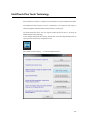
Installing the Driver Software
ELO Touch Solutions provides driver software that allows your touchmonitor to work with your
computer. Drivers are located on the enclosed CD-ROM for the following operating systems:
• Windows 7
• Windows Vista
• Windows XP
• Windows 2000
•
•
•
•
Windows Me
Windows 98
Windows 95
Windows NT 4.0
• Windows 3.1
• MS-DOS
Additional drivers and driver information for other operating systems are available on the ELO
Touch Solutions web site at www.elotouch.com.
The ELO touchmonitor is plug-and-play compliant. Information on the video capabilities of
your touchmonitor is sent to your video display adapter when Windows starts. If Windows
detects your touchmonitor, follow the instructions on the screen to install a generic plug-andplay monitor.
Refer to the following appropriate section for driver installation instructions.
Depending upon whether you connected the serial communication cable or the USB
communication cable, only the serial driver or the USB driver should be installed.
3-5
Installing the Serial Touch Driver (not applicable to Acoustic
Pulse Recognition and IntelliTouch Plus monitor)
Installing the Serial Touch Driver for Windows 7, Windows Vista,
Windows XP, Windows 2000, ME, 98/95 and NT4.0.
NOTE: For Windows 2000 and NT4.0 you must have administrator access rights to install the driver.
Make sure the serial connector (RS232) is plugged into the monitor and an open com port on the PC.
1 Insert the ELO CD-ROM in your computer's CD-ROM drive.
2 If the AutoStart feature for your CD-ROM drive is active, the system automatically detects
the CD and starts the setup program.
3 Follow the directions on the screen to complete the driver setup for your version of
Windows.
4 If the AutoStart feature is not active:
5 Click Start > Run.
6 Click the Browse button to locate the EloCd.exe program on the CD-ROM.
7 Click Open, then OK to run EloCd.exe.
8 Follow the directions on the screen to complete the driver setup for your version of
Windows.
3-6
Installing the Serial Touch Driver for MS-DOS and Windows 3.1
You must have a DOS mouse driver (MOUSE.COM) installed for your mouse if you wish to
continue using your mouse along with your touchmonitor in DOS.
To install Windows 3.x and MS-DOS touch driver from Windows 95/98, follow the directions
below:
1 Insert the CD-ROM in your computer’s CD-ROM drive.
2 From DOS, type d: and press the Enter key to select the CD-ROM (your CD-ROM drive
may be mapped to a different drive letter).
3 Type cd\elodos_w31 to change to the correct directory.
4 Type Install and press Enter to start the installation.
5 Calculate the touchscreen.
3-7
Installing the USB Touch Driver
Installing the USB Touch Driver for Windows 7, Windows Vista, Windows XP,
Windows 2000, ME and Windows 98.
1 Insert the ELO CD-ROM in your computer’s CD-ROM drive.
If Windows 2000 or Windows 98 starts the Add New Hardware Wizard, do the following:
2 Choose Next. Select “Search for the best driver for your device (Recommended)” and
choose Next.
3 When a list of search locations is displayed, place a checkmark on “Specify a location” and
use Browse to select the \EloUSB directory on the ELO CD-ROM.
4 Choose Next. Once the ELO USB touchscreen driver has been detected, choose Next again.
5 You will see several files being copied. Insert your Windows 98 cd if prompted. Choose
Finish.
If Windows 2000 or Windows 98 does not start the Add New Hardware Wizard, do the
following:
NOTE: For Windows 2000 you must have administrator access rights to install the driver.
1 Insert the ELO CD-ROM in your computer’s CD-ROM drive. If the AutoStart feature for
your CD-ROM drive is active, the system automatically detects the CD and starts the setup
program.
2 Follow the directions on the screen to complete the driver setup for your version of
Windows.
If the AutoStart feature is not active:
1 Click Start > Run.
2 Click the Browse button to locate the EloCd.exe program on the CD-ROM.
3 Click Open, then OK to run EloCd.exe.
4 Follow the directions on the screen to complete the driver setup for your version of
Windows.
Installing APR USB Touch Driver for Windows 7, Windows Vista and
Windoows XP
Insert the ELO APR CD-ROM in your computer’s CD-ROM driver.
Follow the directions on the screen to complete the APR 3.1 driver setup for your version of
Windows. Do not plug USB cable until software is fully loaded. When finished, plug USB
cable and alignment data is transferred.
NOTE: For the latest driver, go to elotouch.com and download it from the driver download section.
3-8
CHAPTER
3
OPERATION
About Touchmonitor Adjustments
Your touchmonitor will not likely require adjustment. However, variations in video output and
application may require adjustments to the touchmonitor to optimize the quality of the display.
For best performance, your touchmonitor should be operating in native resolution, that is 1280
x 1024 at 80k-75 Hz. Use the Display control panel in Windows to choose 1280 x 1024
resolution.
Operating in other resolutions will degrade video performance. For further information, please
refer to Appendix A.
All adjustments made to the controls are automatically memorized. This feature saves you from
having to reset the choices every time the touchmonitor is unplugged or powered off and on. If
there is a power failure, the touchmonitor settings will not default to the factory specifications.
3-9
Rear Panel Controls
SEL
MENU
1
2
Control
1 Menu/Exit
2
3
4
5
Function
Display/exits the On Screen Display (OSD) menus.
1. Enter contrast of the OSD.
2. Increase value of the adjustment item.
3. Select item clockwise.
1. Enter brightness adjustment.
2. Decrease value of the adjustment item.
3. Select item counter-clockwise.
Selects the adjustment items from the OSD menus.
Switches the power of the monitor.
3
4 Select
5 Power Switch
Remote OSD Buttons(option)
AUTO/SEL DOWN
UP
3
Control
1 AUTO/SEL
2 DOWN
3 UP
4 MENU
MENU
4
Function
Selects the adjustment items from the OSD menus.
1. Enter brightness adjustment.
2. Decrease value of the adjustment item.
3. Select item counter-clockwise.
1. Enter contrast of the OSD.
2. Increase value of the adjustment item.
3. Select item clockwise.
Display/exits the On Screen Display (OSD) menus.
3-10
Controls and Adjustment
On Screen Display (OSD) Menu Functions
To Display and Select the OSD Functions:
1 Press the Menu key to activate the OSD menu.
2 Use or to move clockwise or counter-clockwise through the menu. Press the Select
key, the parameter will be highlighted when selected.
3 To quit the OSD screen at any time during the operation, press the Menu key. If no keys are
pressed for a short time period, the OSD automatically disappears.
NOTE: The OSD screen will disappear if no input activities are detected for 45 seconds(default).
3-11
On Screen Display (OSD) Control Options
Control
Contrast
Brightness
V-Position
Description
Increases or decreases contrast.
Increases or decreases brightness.
Moves the screen up or down.
H-Position
Recall Defaults
Moves the screen left or right.
Returns the monitor to its default settings.
RGB
Press or
to select 9300, 6500, 5500, 7500 and USER.
Only when selecting USER you can make adjustments to the
R/G/B content.
Press Enter to restore to factory default setting.
Exit the menu.
Exit
Sharpness
Phase
Clock
Adjusts the sharpness.
Increases or decreases the snow noise of the image after auto
adjustment is made.
The dot clock is fine-adjusted after auto adjust.
OSD H-Position
OSD V-Position
OSD Time
Moves the OSD position horizontally on the screen.
Moves the OSD position vertically on the screen.
Determines how long (in seconds) the OSD menu waits before
closing automatically after no action has been performed.
Auto-Adjust
Press Auto to enable this function. The Auto-Adjust will
automatically adjust V-Position, H-Position, Clock and
Clock-Phase.
OSD Language
Information Description
Select from English, French, German, Spanish, and Japanese.
Indicates the current resolution, H-Frequency and
V-Frequency.
3-12
Preset Modes
To reduce the need for adjustment for different modes, the monitor has default setting modes
that are most commonly used as given in the table below. If any of these display modes are
detected, the monitor automatically adjusts the picture size and centering. When no mode is
matched, the user can store their preferred modes in the user modes. The monitor is capable of
storing up to 7 user modes. The only condition to store as a user mode is the new display
information must have 1 KHz difference for horizontal frequency or 1 Hz for vertical frequency
or the sync signal polarities are different from the default modes.
Mode
H. Freq. Band Width
H
V
Resolution
(KHz)
(MHz)
1
2
3
CGA 512 x 247 60 Hz
CGA 512 x 256 60 Hz
VGA 640 x 350 70 Hz
16.858
16.158
31.47
11.059
11.059
28.322
+
+
-
4
5
6
7
8
VGA 720 x 400 70 Hz
VGA 640 x 480 60 Hz
MAC 640 x 480 66 Hz
VESA 640 x 480 72 Hz
VESA 640 x 480 75 Hz
31.47
31.47
35.00
37.86
37.50
28.322
25.175
32.24
31.5
31.5
-
+
-
9
10
11
12
VESA 800 x 600 56 Hz
VESA 800 x 600 60 Hz
VESA 800 x 600 75 Hz
VESA 800 x 600 72 Hz
35.16
37.88
46.88
48.08
36
40
49.5
50
+
+
+
+
+
+
+
+
13
14
15
16
17
MAC 832 x 624 75 Hz
VESA 1024 x 768 60 Hz
SUN 1024 x 768 65 Hz
VESA 1024 x 768 70 Hz
VESA 1024 x 768 75 Hz
49.72
48.36
52.45
56.48
60.02
57.283
65
70.49
75
78.75
+
+
18
19
20
21
SXGA 1280 x 1024 60 Hz
SXGA 1280 x 1024 75 Hz
SXGA 1152 x 864 75 Hz
SXGA 1280 x 960 60 Hz
64
80
67.5
60
108
135
108
108
+
+
+
+
+
+
+
+
3-13
Power
Mode
On
Sleep
Off
Power
Consumption
<50W
<3W
<1W
We recommend switching the monitor off when it is not in use for a long time.
NOTE: Complies to VESA Power Management (DPM) standards. To activate the monitor, press any key on the
keyboard or move the mouse or touch the touchscreen. In order for the touchscreen to bring the monitor from
the DPM system, the touchscreen function must be fully operational.
3-14
IntelliTouch Plus Touch Technology
When connected to Windows 7 computers, the touchmonitor can report 2 simultaneous touches.
The IntelliTouch Plus touchscreen can be re-calibrated to your displayed video image, if
needed, through the Calibration function in the ELO driver control panel.
The IntelliTouch Plus driver will only support multiple monitor if they are all using the
IntelliTouch Plus touch technology.
To use multiple IntelliTouch Plus monitors, double click on the EloConfig desktop shortcut to
open up the ELO Touchscreen Configuration screen.
Select “Match Touch to Display…” to calibrate multiple monitors.
3-15
Gesture Support
The IntelliTouch Plus touch technology enable several gestures that support single and multiple
contacts. Refer to the Microsoft Website http://msdn.microsoft.com/en-us/library/dd940543 on
the various gestures that are supported in Windows 7.
3-16
CHAPTE R
4
TROUBLESHOOTING
If you are experiencing trouble with your touchmonitor, refer to the following table. If the
problem persists, please contact your local dealer or our service center.
Solutions to Common Problems
Problem
The monitor does not respond
when turning on the system.
Suggestion(s)
1. Check that the monitor’s Power Switch is on.
2. Turn off the power and check the monitor’s DC power cord
and signal cable for proper connection.
Characters on the screen are dim
Refer to the About Touchmonitor Adjustments section to adjust
the brightness.
The video is blank
1. During operation, the monitor screen may automatically turn
off as a result of the Power Saving feature. Press any key to see
if the screen reappears.
2. Refer to the About Touchmonitor Adjustments section to
adjust the brightness.
Screen flashes when initialized
Turn the monitor off then turn it on again.
“Out of Range” display
Reconfigure the resolution of your computer to make one of the
monitor’s supported video mode (see Appendix C).See Appendix A
for more information on resolution.
Touch doesn’t work
Make sure the touch cable is securely attached at both ends.
4-17
APPENDIX
A
NATIVE RESOLUTION
The native resolution of a monitor is the resolution level at which the LCD panel is designed to
perform best. For the LCD touchmonitor, the native resolution is 1280 x 1024 for the 19 inch
size. In almost all cases, screen images look best when viewed at their native resolution. You
can lower the resolution setting of a monitor but not increase it.
Input Video
512 x 247 (CGA)
512 x 256 (CGA)
640 x 480 (VGA)
19" LCD
Transforms input format to 1280 x 1024
800 x 600 (SVGA)
1024 x 768 (XGA)
1280 x 1024 (SXGA)
Transforms input format to 1280 x 1024
Displays in Native Resolution
The native resolution of an LCD is the actual number of pixels horizontally in the LCD by the
number of pixels vertically in the LCD. LCD resolution is usually represented by the following
symbols:
CGA
512 x 247
CGA
VGA
512 x 256
640 x 480
SVGA
XGA
800 x 600
1024 x 768
SXGA
1280 x 1024
A-18
As an example, a SXGA resolution LCD panel has 1280 pixels horizontally by 1024 pixels
vertically. Input video is also represented by the same terms. SXGA input video has a format of
1280 pixels horizontally by 1024 pixels vertically. When the input pixels contained in the video
input format match the native resolution of the panel, there is a one to one correspondence
of mapping of input video pixels to LCD pixels. As an example, the pixel in column 45 and
row 26 of the input video is in column 45 and row 26 of the LCD. For the case when the input
video is at a lower resolution than the native resolution of the LCD, the direct correspondence
between the video pixels and the LCD pixels is lost. The LCD controller can compute the
correspondence between video pixels and LCD pixels using algorithms contained on its
controller. The accuracy of the algorithms determines the fidelity of conversion of video pixels
to LCD pixels. Poor fidelity conversion can result in artifacts in the LCD displayed image such
as varying width characters.
A-19
APPENDIX
B
TOUCHMONITOR SAFETY
This manual contains information that is important for the proper setup and maintenance of
your touchmonitor. Before setting up and powering on your new touchmonitor, read through
this manual, especially Chapter 2 (Installation), and Chapter 3 (Operation).
1 To reduce the risk of electric shock, follow all safety notices and never open the
touchmonitor case.
2 Turn off the product before cleaning.
3 The slots located on the sides and top of the touchmonitor case are for ventilation. Do not
block or insert anything inside the ventilation slots.
4 It is important that your touchmonitor remains dry. Do not pour liquid into or onto your
touchmonitor. If your touchmonitor becomes wet do not attempt to repair it yourself.
Ensure that your installation/setup is designed/equipped to maintain operating temperature
within the specified operating conditions (refer to the section TouchMonitor Specifications).
B-20
Care and Handling of Your Touchmonitor
The following tips will help keep your touchmonitor functioning at the optimal level.
• To avoid risk of electric shock, do not disassemble the brick power supply or display unit
cabinet. The unit is not user serviceable. Remember to unplug the display unit from the
power outlet before cleaning.
• Do not use alcohol (methyl, ethyl or isopropyl) or any strong dissolvent. Do not use thinner
or benzene, abrasive cleaners or compressed air.
• To clean the display unit cabinet, use a cloth lightly dampened with a mild detergent.
• Avoid getting liquids inside your touchmonitor. If liquid does get inside, have a qualified
service technician check it before you power it on again.
• Do not wipe the screen with a cloth or sponge that could scratch the surface.
• To clean the touchscreen, use window or glass cleaner. Put the cleaner on a clean cloth and
wipe the touchscreen. Never apply the cleaner directly to the touchscreen.
Warning
This product consists of devices that may contain mercury, which must be recycled or disposed
of in accordance with local, state, or federal laws. (Within this system, the backlight lamps in
the monitor display contain mercury.)
Waste Electrical and Electronic Equipment(WEEE) Directive
In the European Union, this label indicates that this product should not be disposed of with
household waste. It should be deposited at an appropriate facility to enable recovery and
recycling.
B-21
APPENDIX
C
TECHNICAL SPECIFICATIONS
C-22
Touchmonitor Specifications
Model
LCD Display
Display Size
Pixel Pitch
Display Mode
1937L
19” TFT Active Matrix Panel
376.32(H) x 301.056(V) mm
0.294(H) x 0.294(V) mm
512 x 247 @ 60Hz
512 x 248 @ 60Hz
640 x 350 @ 70Hz
640 x 480 @ 60, 66, 72, 75Hz
720 x 400 @ 70Hz
800 x 600 @ 56, 60, 72, 75Hz
832 x 624 @ 75Hz
1024 x 768 @ 60, 65, 70, 75Hz
1280 x 960 @ 60Hz
1280 x 1024 @ 60,75Hz
1280 x 1024
800 : 1 (typical)
No touch screen: typical 250 cd/m2; min. 200cd/m2
IntelliTouch: typical 225 cd/m2 ; min. 170cd/m2
AccuTouch: typical 200 cd/m2 ; min. 150cd/m2
Acoustic Pulse Recognition: typical 225 cd/m2 ; min. 170cd/m2
Native Resolution
Contrast Ratio
Brightness
Response Time (Rise + Fall)
Display Color
Viewing Angle
Vertical
Horizontal
Input Signal
Video
Sync
Signal Connector
Rear Controls
On Screen Display (OSD) Controls
Plug & Play
Touch Panel (optional)
Operating Conditions
Storage Conditions
Dimensions (HxWxD)
Weight (Net)
Certifications
Temperature
Humidity
Altitude
Temperature
Humidity
IntelliTouch Plus: typical 225 cd/m2 ; min. 170cd/m2
5ms (typical) ; 10ms max.
16.7M
CR>10, 80 deg (Up) / 80 deg (Down) typical
70 deg (Up) / 70 deg (Down) min.
CR>10, 80 deg (Left) / 80 deg (Right) typical
70 deg (Left) / 70 deg (Right) min.
R.G.B. Analog 0.7Vp-p, 75 ohm
TTL Positive or Negative
Mini D-Sub 15 pin
Menu,
, , Select, Power
Contrast, Brightness, H-Position, V-Position, Sharpness
Color Temperature, Phase, Clock, OSD Time, Recall,
Language: English, French, German, Spanish, Japanese
DDC2B
IntelliTouch/AccuTouch /Acoustic Pulse Recognition
IntelliTouch Plus
o
o
o
o
0 C ~ 40 C (32 F ~ 104 F)
20% ~ 80% (No Condensation)
To 10,000 Feet
o
o
o
o
-20 C ~ 60 C (-4 F ~ 140 F)
10% ~ 90% (No Condensation)
343 x 415 x 51mm
5.2Kg
UL, CUL ,TUV ,CE ,FCC ,ICES-003 ,VCCI ,C-Tick ,NOM ,
Argentina S-mark ,CCC, China RoHS, KC, BSMI
C-23
19" LCD Touchmonitor (1937L) Dimensions
1-----m--
0
::;;0000000
0000000
mm:mm:::
B -:;;, :-:Ei
""
''"
0 0 ..
•
364
""
"'
m
•
:1=
•
..
. .
?
•
•
.
'
"
!"."
•• •
t::::Jc
I'
I
r
'
'
='·
L
'
436
50 0 FQR
I, -
,,
(CENTERING LIPJ
C-24
REGULATORY INFORMATION
I. Electrical Safety Information:
A) Compliance is required with respect to the voltage, frequency, and current requirements
indicated on the manufacturer’s label. Connection to a different power source than those
specified herein will likely result in improper operation, damage to the equipment or
pose a fire hazard if the limitations are not followed.
B) There are no operator serviceable parts inside this equipment. There are hazardous
voltages generated by this equipment which constitute a safety hazard. Service should be
provided only by a qualified service technician.
C) Contact a qualified electrician or the manufacturer if there are questions about the
installation prior to connecting the equipment to mains power.
II. Emissions and Immunity Information
A) Notice to Users in the United States: This equipment has been tested and found to
comply with the limits for a Class B digital device, pursuant to Part 15 of FCC Rules.
These limits are designed to provide reasonable protection against harmful interference
in a residential installation. This equipment generates, uses, and can radiate radio
frequency energy, and if not installed and used in accordance with the instructions, may
cause harmful interference to radio communications.
B) Notice to Users in Canada: This equipment complies with the Class B limits for radio
noise emissions from digital apparatus as established by the Radio Interference
Regulations of Industrie Canada.
C) Notice to Users in the European Union: Use only the provided power cords and
interconnecting cabling provided with the equipment. Substitution of provided cords and
cabling may compromise electrical safety or CE Mark Certification for emissions or
immunity as required by the following standards:
This Information Technology Equipment (ITE) is required to have a CE Mark on the
manufacturer’s label which means that the equipment has been tested to the following
Directives and Standards: This equipment has been tested to the requirements for the CE
Mark as required by EMC Directive 2004/108/EC indicated in European Standard EN
55022 Class B and the Low Voltage Directive 2006/95/EC as indicated in European
Standard EN 60950.
25
D) General Information to all Users: This equipment generates, uses and can radiate radio
frequency energy. If not installed and used according to this manual the equipment may
cause interference with radio and television communications. There is, however, no
guarantee that interference will not occur in any particular installation due to site-specific
factors.
1) In order to meet emission and immunity requirements, the user must observe the
following:
a) Use only the provided I/O cables to connect this digital device with any
computer.
b)To ensure compliance, use only the provided manufacturer’s approved line
cord.
c) The user is cautioned that changes or modifications to the equipment not
expressly approved by the party responsible for compliance could void the
user’s authority to operate the equipment.
2) If this equipment appears to cause interference with radio or television reception,
or any other device:
a) Verify as an emission source by turning the equipment off and on.
b) If you determine that this equipment is causing the interference, try to
correct the interference by using one or more of the following measures:
i) Move the digital device away from the affected receiver.
ii) Reposition (turn) the digital device with respect to the affected receiver.
iii)Reorient the affected receiver’s antenna.
iv)Plug the digital device into a different AC outlet so the digital device
and the receiver are on different branch circuits.
v) Disconnect and remove any I/O cables that the digital device does not
use. (Unterminated I/O cables are a potential source of high RF
emission levels.)
vi)Plug the digital device into only a grounded outlet receptacle. Do not
use AC adapter plugs. (Removing or cutting the line cord ground may
increase RF emission levels and may also present a lethal shock hazard
to the user.)
If you need additional help, consult your dealer, manufacturer, or an experienced radio or
television technician.
26
III. Agency Certifications
The following certifications have been issued for this monitor:
•
Argentina S-Mark
•
•
•
•
Australia C-Tick
Canada CUL
China CCC
China RoHS
•
•
•
•
•
Germany TUV
Europe CE
Japan VCCI
Mexico NOM
United States FCC
•
•
•
United States UL
Korea KC
Taiwan BSMI
27
WARRANTY
Except as otherwise stated herein or in an order acknowledgment delivered to Buyer, Seller
warrants to Buyer that the Product shall be free of defects in materials and workmanship. The
warranty for the touchmonitors and components of the product is 3 (three) years.
Seller makes no warranty regarding the model life of components. Seller’s suppliers may at any
time and from time to time make changes in the components delivered as Products or
components.
Buyer shall notify Seller in writing promptly (and in no case later than thirty (30) days after
discovery) of the failure of any Product to conform to the warranty set forth above; shall describe
in commercially reasonable detail in such notice the symptoms associated with such failure;
and shall provide to Seller the opportunity to inspect such Products as installed, if possible. The
notice must be received by Seller during the Warranty Period for such product, unless
otherwise directed in writing by the Seller. Within thirty (30) days after submitting such notice,
Buyer shall package the allegedly defective Product in its original shipping carton(s) or a
functional equivalent and shall ship to Seller at Buyer’s expense and risk.
Within a reasonable time after receipt of the allegedly defective Product and verification by
Seller that the Product fails to meet the warranty set forth above, Seller shall correct such
failure by, at Seller’s options, either (i) modifying or repairing the Product or (ii) replacing the
Product. Such modification, repair, or replacement and the return shipment of the Product with
minimum insurance to Buyer shall be at Seller’s expense. Buyer shall bear the risk of loss or
damage in transit, and may insure the Product. Buyer shall reimburse Seller for
transportation cost incurred for Product returned but not found by Seller to be defective.
Modification or repair, of Products may, at Seller’s option, take place either at Seller’s facilities
or at Buyer’s premises. If Seller is unable to modify, repair, or replace a Product to conform
to the warranty set forth above, then Seller shall, at Seller’s option, either refund to Buyer or
credit to Buyer’s account the purchase price of the Product less depreciation calculated on a
straight-line basis over Seller’s stated Warranty Period.
28
THESE REMEDIES SHALL BE THE BUYER’S EXCLUSIVE REMEDIES FOR BREACH
OF WARRANTY. EXCEPT FOR THE EXPRESS WARRANTY SET FORTH ABOVE,
SELLER GRANTS NO OTHER WARRANTIES, EXPRESS OR IMPLIED BY STATUTE OR
OTHERWISE, REGARDING THE PRODUCTS, THEIR FITNESS FOR ANY PURPOSE,
THEIR QUALITY, THEIR MERCHANTABILITY, THEIR NONINFRINGEMENT, OR
OTHERWISE. NO EMPLOYEE OF SELLER OR ANY OTHER PARTY IS AUTHORIZED
TO MAKE ANY WARRANTY FOR THE GOODS OTHER THAN THE WARRANTY SET
FORTH HEREIN. SELLER’S LIABILITY UNDER THE WARRANTY SHALL BE
LIMITED TO A REFUND OF THE PURCHASE PRICE OF THE PRODUCT. IN NO EVENT
SHALL SELLER BE LIABLE FOR THE COST OF PROCUREMENT OR INSTALLATION
OF SUBSTITUTE GOODS BY BUYER OR FOR ANY SPECIAL, CONSEQUENTIAL,
INDIRECT, OR INCIDENTAL DAMAGES.
Buyer assumes the risk and agrees to indemnify Seller against and hold Seller harmless from
all liability relating to (i) assessing the suitability for Buyer’s intended use of the Products and
of any system design or drawing and (ii) determining the compliance of Buyer’s use of the
Products with applicable laws, regulations, codes, and standards. Buyer retains and accepts full
responsibility for all warranty and other claims relating to or arising from Buyer’s products,
which include or incorporate Products or components manufactured or supplied by Seller.
Buyer is solely responsible for any and all representations and warranties regarding the
Products made or authorized by Buyer. Buyer will indemnify Seller and hold Seller harmless
from any liability, claims, loss, cost, or expenses (including reasonable attorney’s fees)
attributable to Buyer’s products or representations or warranties concerning same.
29
Check out Our Website!
www.elotouch.com
Get the latest...
• Product information
• Specifications
• News on upcoming events
• Press release
• Software drivers
• Touchmonitor Newsletter
Getting in Touch with us
To find out more about ELO’s extensive range of ELO Touch Solutions, visit our website at www.elotouch.com or simply call
the office nearest you:
North America
Germany
Belgium
Asian-Pacific
ELO Touch Solutions
301 Constitution Drive,
Menlo Park, CA 94025
USA
ELO Touch Solutions
Finsinger Feld 1
D-85521 Ottobrunn
Germany
ELO Touch Solutions
Diestsesteenweg 692
B-3010 Kessel-Lo
Belgium
ELO Touch Solutions
Sun Homada Bldg. 2F
1-19-20 Shin-Yokohama
Kanagawa 222-0033
Japan
(800) ELO-TOUCH
(800-557-1458)
Tel 650-361-4800
Fax 650-361-4722
Tel +49(0)(89)60822-0
Fax +49(0)(89)60822-180
[email protected]
Tel +32(0)(16)35-2100
Fax +32(o)(16)35-2101
[email protected]
Tel +81(45)478-2161
Fax +81(45)478-2180
www.tps.co.jp
© 2012 ELO Touch Solutions, Inc.
All Rights Reserved.