1
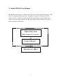
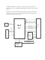
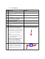
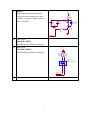
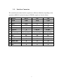
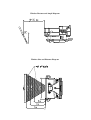
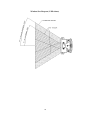
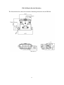
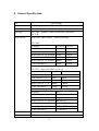
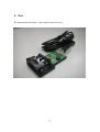
Argox
FM-201
Integration Manual
0
Contents
1.
2.
3.
4.
5.
About FM-201 Scan Engine ..................................................................................... 2
Signal Connector ...................................................................................................... 4
2.1.
J2 Connector ................................................................................................. 5
2.2.
Interface Connector ...................................................................................... 7
Mechanical Specifications ........................................................................................ 8
3.1.
Distance from window ................................................................................. 8
3.2.
Window size and material ............................................................................ 8
General Specification ............................................................................................. 12
Test.......................................................................................................................... 14
1
1. About FM-201 Scan Engine
The FM-201 Scan Engine is a small decoder that can read all popular 1D barcodes. This
device is comprised of two main parts: an optical system and a control board. The
optical system is a 2048 pixel linear imager. The control board contains firmware to
scan, decode and output barcode data. The below block diagram shows the data flow
from control board to the host.
Optical System
(LED, Condenser, Lens, chassis..)
Control Board
Interface to Host
2
The FM-201 Scan Engine is specifically designed for easy integration into your
application devices. The control module supports RS232, Keyboard wedge and USB 1.1
interface.
The control board is based on MCU to fulfill the functions of barcode scanner, image
decoding, parameter settings, and communication with host. The block diagram and
individual description are listed as below,
Txd
RxD
RTS
LED
CTS
LED ( P63 )
(LED1,2 )
MCU
Trigger Switch
P1(P75)
/ P14
Dual LED / P65,P62
P2(P74)
Interface selection (AN4)
KBON
AIN0
P8.2
KBCLK
Bilateral
Switch -
( J1)
74HC4066
10P
( U3)
SCL
SDA
PS2 CLK (P80)
PS2 Data(P81)
EEPROM24WC16
(U2)
3
( J2 )
14P
Buzzer / FTIOB0
(U1 )
TG(P76)
C
C
D
connector
2. Signal Connector
The control module is reserved connection pins for interface, trigger, buzzer, LEDs and
power. J2 is comprised of 14 pins that start from right to left, pin1 to pin 14. The
diagram and description are listed as below:
4
J2 Connector
Pin Description
Example
1
GND.— Supply signal ground
2
RTS ( To Host ) / CLK/KB.— TTL level
232 Request to send
3
RxD ( From Host ).— TTL level 232
receive data
4
CTS ( From Host ) / DATA/KB.— TTL
level 232 Clear to Send signal.
5
DATA/PC ( PS2 DATA ).
6
CLK/PC ( PS2 CLK ).
7
TxD ( To Host ).—TTL level 232
transmit data.
8
5 V DC input—Supply voltage input.
9
I/F identification . According to the
voltage level at I/F, the scanner will
Wire I/F with a 4.7K then ground
R4
automatically select a communication
Interface, when the interface selection of
scanner being set at auto-detection
mode.
The followings list the interface
selection corresponding to the various
voltage level at I/F.
4.7K/0603
2.1.
I/F floating-NC: Identified as RS232
I/F short to GND: Identified as
Keyboard wedge. Wire I/F with a
4.7K then ground : Identified as USB
10
Trigger Switch(SW1)
To trigger off a scanning operation..
P14 of CPU is wired to the SW1 to read
the SW1 status, pressed or released.
5
SW1
GND
GND
1
2
3
4
Tack Switch
STS-KB5
SERIES
TRIGEER
TRIGEER
+5V
R8
33R
R0603
+
Buzzer
To provide the indication of sound.
The generation of frequency & duty
( loudness) of buzzer sound is done by
Timer Z in CPU
C21
10uF
C22
0.1uF
Buzzer
C0603
D2
1N4148
SOD80C
3
C0805
-
11
1
2
R7
1K
Q2
2N2222
SOT-23
R0603
BUZZER
12
GRE_LED.
Dual LED (LED3)
Dual Red&Green LED for indication.
13
RED_LED.
+5V
Dual LED (LED3)
Dual Red&Green LED for indication.
R33
220R
R0603
R9
220R
R0603
Red/Greed LED
LED4
5690F_0 Dual LED
RED_LED
GRE_LED
14
N.C.
6
2.2.
Interface Connector
The control board to host interface signals have different definitions depending on the
operation of RS232, keyboard wedge or USB.The signals are listed as below:
Pin Signal
RS232
K/B
USB
1
GND
GND
GND
GND
2
RTS(CLK KB)
RTS
CLK KB
X
3
RxD
RxD
X
X
4
CTS(DATA KB)
CTS
DATA KB
X
5
DATA PC
X
DATA PC
DATA PC
6
CLK PC
X
CLK PC
CLK PC
7
TxD
TxD
X
X
8
Vcc(DC 5V)
Vcc(DC 5V)
Vcc(DC 5V)
Vcc(DC 5V)
9
I/F
I/F
I/F
I/F
10
Trigger
X
X
X
11
Buzzer
X
X
X
12
GRE_LED
X
X
X
13
RED_LED
X
X
X
14
NC
X
X
X
7
3. Mechanical Specifications
3.1.
Distance from window
The window should be mounted close to the front of the Scan Engine. The maximum
distance is measured from the Scan Engine housing to the farther surface of the window.
The unwanted reflections can occur at either surface and the window thickness can vary,
the further side is the worse case.
3.2.
Window size and material
1. Window material must be clear and anti-scratch. Clarx, Polycarbonate and CR39 are
preferred.
2. The recommended thickness of window is from 1mm to 15 mm.
3. The recommended distance is from 10 mm to 35 mm between window and engine.
4. The recommended angle is from 0 to 28 degree .
5. The window size must increase as it is moved away from the engine to the
accommodate illumination.
8
Window Distance and Angle Diagram
Window Size and Distance Diagram
9
Window Size Diagram ( LED Aimer)
10
FM-201 Engine Bracket Mounting
The illustration below show the mechanical mounting dimensions for the FM-201
11
4. General Specification
Item
Specification
Scanning system
Red LED light source. 2048 pixels CCD.
Resolution
4 mil (0.10mm).
Scan angle
Pitch: <60°
Yaw: <70°
Depth of field
Ambient lux: 300 +/-30 lux
(EAN13, 13mil, 35 mm wide , PCS=90%)
(fluorescent lamp).
PCS = 90%.
Resolution
Near field
Far field
4 mil (Code 39, 1:2.5) ,
45mm
70mm
5 mil (Code 39, 1:2.5)
45mm
80mm
10 mil (Code 39, 1:2.5)43mm 45 mm
125mm
13 mil (Code 39, 1:2.5)83mm 90mm
155mm
20 mil (Code 39, 1:2.5)95mm 100mm
195mm
13 mil (UPC/EAN)
155mm
45 mm
PCS =45%. (Argox Test Chart) < note 1>
Resolution
Near field
4 mil (Code 39, 1:2.5)
X
5 mil (Code 39, 1:2.5)
45mm
Far field
60mm
13 mil (Code 39, 1:2.5) 90mm
110mm
20 mil (Code 39, 1:2.5) 105mm
140mm
13 mil (UPC/EAN)
115mm
45 mm
Resolution
Data
4 mil (Code 39, 1:2.5)
09876
5 mil (Code 39, 1:2.5)
01234
10 mil (Code 39, 1:2.5)43mm ARGOX-123
13 mil (Code 39, 1:2.5)83mm 83MM CODE-39-1
20 mil (Code 39, 1:2.5)95mm 95MM -CODE
13 mil (UPC/EAN)
471987654321
Scan rate
30~100 sacn/second, auto adaptive.
PCS
>= 45%
12
Reading indication LED and adjustable beep sound (Add LED&Buzzer yourself)
Symbologies
Code-11, Code-39, Code-93, Code-128, Codabar, EAN-8/13
(with add-on), UPC-A/E UPCE (with add-on).
MSI/Plessey ,UK/Plessey, Telepen
Industrial 2 of 5, Interleaved 2 of 5, Standard 2 of 5, , Matrix 2 of
5 Eur.China postage. Italian Pharmacy code (code-32).
RSS-14, RSS-limited, RSS-expanded.
Power supply
Operating range: 5 VDC +/-0.25 (Scanner only)
Power consumption:
Scanning: Max.: 250 mA (Test Mode).
Typical: Max.: 200 mA (Momentary Mode)
Standby: Max.: 60 mA
Environments
Operating temp.: 0~50 °C
Storage temp.: -20~+70 °C
Ambient LUX.: 0~20000 Lux
13
The illustration below show s a unit similar to the unit tested.
14