1
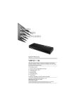
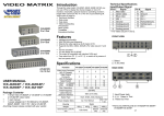
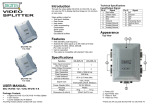
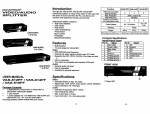
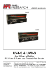
Introduction Through the video/audio matrix DC-48101, you can display / play different images / audio signals to 4 screens / speakers (or earphones) through 4 PC. And you can also control the source of image / audio by selecting PC signal source 1 ~ 4 or turning off source input. VIDEO / AUDIO MATRIX SWITCH Video/Audio matrix is ideal for: Test bench facilities Data center Help desks Video broadcasting: Presentation Stock quotes Timetables Educational facilities Technical Specifications Input/Output Signal Pin # 1 2 3 4 5 6 7 8 Signal Red video Green video Blue video NC Ground Analog ground Analog ground Analog ground Pin # 9 10 11 12 13 14 15 Signal NC Ground NC ID1 Horizontal sync Vertical sync ID3 FRONT VIEW Features (DC-48101) 4 In 4 Out Intelligent functionality. With 350 MHz pixel frequency. Support VGA, SVGA, UXGA, QXGA resolutions. Support Multi-Sync video type include RGBHV, RGsB, RGBS. Support synchronous Include positive, negative; TTL or 1Vpp level. Supports the DDC, DDC2, DDC2B. Four sets of 7-Segment LED can indicate the input setting status of input port quickly. The output is compatible with standard VGA card. Extends the video signal up to 65 meter (213 feet). Audio Frequency Response 20Hz~20KHz. The switches on panel can select PC signal source 1 ~ 4 as OUT 1 ~ 4 or turning off any signal I/O port / all I/O ports. Can be cascaded. Specifications USER MANUAL Package Contents DC-48101 video/audio matrix 1 user manual 1 power adapter DC 12V 1.25A 2 rack rails, 8 screws Any thing missed, please contact with your vendor. Function DC-48101 Video Input Connector Video Output Connector Audio Input Connector Audio Output Connector Select Switch 7-Segment LED Max. Resolution Pixel Frequency Cable Distance (Device to Monitor) Power Adapter (Min.) Housing Weight Dimensions (LxWxH) 4x HD-15 Female 4x HD-15 Female 4x 3.5φ Stereo Jack 4x 3.5φ Stereo Jack 10 4 1920x1440 @ 85 Hz 350 MHz 65m (213 feet) Max. DC 12V 1.25A Metal 1065 g 269x108x42 mm -1- 1. Select Switch 2. 7-Segment LED REAR VIEW 1. Input Power Jack 2. “Audio Out” Port 3. “Audio In” Port 4. “Video Out” Port 5. “Video In” Port Installation 1. Turn off the power switches of PC, screens, and speakers. 2. Use HD-15 image / 3.5φ earphone extension cable to connect VGA interface / audio card in PC and the “Video In“ & “Audio In“ jack of video/audio matrix. 3. Use HD-15 image / 3.5φ earphone extension cable to connect screen, speaker, or earphone and the “Video Out“ & “Audio Out“ jack of video/audio matrix. 4. Connect video/audio matrix to power supply. 5. Turn on the power switches of PC, screens, and speakers. 6. Control switches, which includes “Out1“, “Out2“, “Out3“, “Out4“, “All“, “In1“, “In2“, “In3“, “In4“, and “OFF“, on panel can get image / audio signals or turn off input signal through output jack. -2- Operation Operation for cascade: 1. When you press button “Out1“ or “Out2“ or “Out3“ or “Out4“, 1. The function to display image on more monitors, you request to attach another video/audio matrix or the standard video/audio splitter. 2. Connect the HD-15 male/male video extension cable between the “Video Out” port of the former video/audio matrix and the “Video In” port of the latter video/audio matrix. 3. Connect the 3.5φ Stereo plug male/male audio extension cable between the “Audio Out” port of the former video/audio matrix and the “Audio In” port of the latter video/audio matrix. the corresponding Out 7-Segment LED will start flashing for 3 seconds. There are total three switching methods: a. a. Press button “In1“ or “In2“ or “In3“or “In4“ within 3 seconds to make 7-Segment LED stop flashing and change its display to the number of Input port you set. Then the Output port will switch to the corresponding Input port. b. b. Press button ”OFF” within 3 seconds to make 7-Segment LED stop flashing and display ”0”. Then this Output port will be turned off. c. c. If you don’t press any button within 3 seconds, the 7-Segment LED will stop flashing and keep displaying original number and setting of Output port. d. d. If you press button “Out1“ or “Out2“ or “Out3“ or “Out4“ within 3 seconds, then Out 7-Segment LED will start flashing for 3 seconds again to wait for button “In1“ or “In2“ or “In3“ or “In4“, “OFF” pressed. 2. When you press button ”All”, all 7-Segment LED will start flashing for 3 seconds. There are total three switching methods: a. Press button “In1“ or “In2“ or “In3“or “In4“ within 3 seconds to make all 7-Segment LED stop flashing and change their displays to the number of Input ports you set. Then all Output ports will switch to the corresponding Input ports. b. Press button ”OFF” within 3 seconds to make all 7-Segment LED stop flashing and display ”0”. Then all Output ports will be turned off. c. If you don’t press any button within 3 seconds, all 7-Segment LED will stop flashing and keep displaying original number and setting of Output port. d. If you press button “All“ within 3 seconds, then all Out 7-Segment LED will start flashing for 3 seconds again to wait for button “In1“ or “In2“ or “In3“ or “In4“, “OFF” pressed. Note: When video/audio matrix is connected to power supply, the initial setting of jack connection is: ”Out1” to ”In1”, ”Out2” to ”In2”, ”Out3” to ”In3”, ”Out4” to ”In4”. If you install DDC monitor for video/audio matrix, then the setting of DDC will be applied to the other monitors. To get the functionality of DDC monitor, please connect the following jacks: “Video In1” to “Video Out1”, “Video In2” to “Video Out2”, “Video In3” to “Video Out3”, and “Video In4” to “Video Out4”. Available monitors include the VGA, SVGA, UXGA, QXGA, Multisync, and exclude the CGA, EGA, Mono. -3- Note: Even though you are allowed to cascade the video/audio matrix with varied ports, the image might become unstable if cascade too many tiers of video/audio matrixes. Trademarks: All the companies, brand names, and product names referred to this manual are the trademarks or registered trademarks belonging to their respective companies. -4-