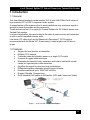
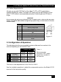
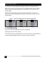
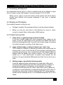
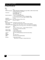
1
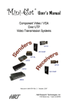
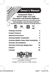
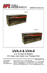
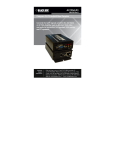
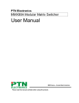
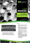
User’s Manual UV4-S UV8-S UV4-S & UV8-S 4 or 8 Channel Splitter PC Video & Power over Twisted-Pair Sender CUSTOMER SUPPORT INFORMATION UMA1177 Rev. NC Order toll-free in the U.S. 800-959-6439 FREE technical support, Call 714-641-6607 or fax 714-641-6698 Address: Hall Research, 1163 Warner Ave. Tustin, CA 92780 Web site: www.hallresearch.com E-mail: [email protected] 4 or 8 Channel Splitter PC Video & Power over Twisted-Pair Sender TRADEMARKS USED IN THIS MANUAL Hall Research and its logo are trademarks of Hall Research. Any other trademarks mentioned in this manual are acknowledged as the property of the trademark owners. FEDERAL COMMUNICATIONS COMMISSION RADIO FREQUENCY INTERFERENCE STATEMENT This equipment generates, uses, and can radiate radio frequency energy and if not installed and used in strict accordance with the manufacturer’s instructions, may cause interference to radio communication. This equipment is designed to comply with the limits for a Class A computing device in accordance with the specifications in Subpart B of Part 15 of FCC rules, which are intended to provide reasonable protection against such interference when the equipment is operated in a commercial environment. Operation of this equipment in a residential area is likely to cause interference, in which case the user at their own expense will be required to take whatever measures may be necessary to correct the interference. Changes or modifications not expressly approved by the party responsible for compliance could void the user’s authority to operate the equipment. 1 Model UV4-S and UV8-S Contents 1. Introduction .....................................................................3 1.1 General .........................................................................3 1.2 Features ........................................................................3 2. Installation .......................................................................4 2.1 Package Contents............................................................4 2.2 Cable Requirements .........................................................5 3. Configuration & Operation..................................................5 4. Troubleshooting ...............................................................6 4.1 Contacting Hall Research...................................................7 4.2 Shipping and Packaging ....................................................7 4.3 Problem Solving FAQ........................................................7 5. Specifications...................................................................8 2 4 or 8 Channel Splitter PC Video & Power over Twisted-Pair Sender 1. Introduction 1.1 General This User Manual applies to model number UV4-S and UV8-S Mini-Cat ® series of high resolution PC or HDTV component video system. A unique feature of the system is that in most installations only one power supply is enough to power the sender and the receiver(s). These devices are four (4) or eight (8) Channel Splitters for PC Video & power over Twisted-Pair senders In a typical application, they are located at the video & power source and connected to one or more compatible receiver units. Low-skew UTP cable (such as Hall Research’s Zero-skew™ CAT5 cable) is recommended with the Model UV1-R particularly if cable lengths are 200 feet or longer. 1.2 Features • • • • • • • • • • Support for local monitor at transmitter Multiple CATx outputs Transmits video and phantom power on a single CATx cable Compact & rugged metal enclosure Eliminates the need for bulky, expensive and hard to build multi-coaxial cables for high-resolution video extension Amplifies the signal for clean and crisp transmission Differential signaling eliminates ground loops and noise Handles resolutions up to 1920x1440 at 60Hz Rugged, Reliable, Compact size Drive standard Cat5 cables to 500 feet for (VGA and Component Video) Figure 1 – UV4-S & UV8-S Application Diagram 3 Model UV4-S and UV8-S 2. Installation 2.1 Package Contents Your package should contain the following items: (1) UV4-S or UV8-S (1) Universal power supply (9 VDC) with IEC320 Power Cord (1) 6 ft HD15-M-M VGA cable (1) User manual (1) Screwdriver 2.2 Connection to Compatible Receivers The UV4-S and UV8-S units have a single UTP cable connection to Hall Research’s UV1-R receiver product line. 4 Connect the UTP cable from the UV1-R receiver to the “UTP OUT” connectors of the UV4-S or UV8-S. Connect the HD15 - “PC/HD IN” connector to the video source. For YPbPr video sources, use a 3-RCA to HD15 cable (Hall Research P/N CHD15RGB). Connect the HD15-“PC/HD OUT” connector to a compatible video display. Connect the included power supply to the center positive +9 VDC power input connector on the UV4-S or UV8-S. o If the UTP cable to the UV1-R receiver is longer than 330 ft (100m) then a power supply may be needed at the receiver (sold separately HR Model # 511-GS569). Never use any other power supply as this may damage the device. 4 or 8 Channel Splitter PC Video & Power over Twisted-Pair Sender 2.2 Cable Requirements All units can use with CAT5/5e/6 or Zero-Skew™ UTP or STP (unshielded or shielded twisted pair) cables. Low-skew UTP cable (such as Hall Research’s Zeroskew™ CAT5 cable) is recommended particularly if cable lengths are 200 feet or longer. IMPORTANT Do not connect this unit to any LAN device such as network cards or hubs as this may cause damage. Use EIA/TIA 568B standard straight-through patch wiring as shown below. Do not use crossover cables. PIN 1 2 3 4 5 6 7 8 EIA/TIA 568B WIRING STANDARD Wire Color White w/ Orange Stripe Orange White w/Green Stripe Blue White w/Blue Stripe Green White w/Brown Stripe Brown Figure 2 3. Configuration & Operation The table below lists the recommended maximum distances from sender to the receiver depending on the resolution used. Resolution Refresh Rate 60 Hz 75 Hz 800x600 500 ft 500 ft 1024x768 1280x1024 1920x1200 500 ft 500 ft 500 ft 500 ft 500 ft 500 ft Table 1 Recommended maximum CATx cable length from sender to the receiver There are no user adjustments on the UV4-S or UV8-S. Use the included screwdriver to adjust the compensation pots on the Model UV1-R receiver for the best picture quality. 5 Model UV4-S and UV8-S 3.1 Receiver Video Adjustment (High Frequency Compensation) Apply a video source to the system and check the image at each receiver’s display. Set the compensation potentiometer (pot) on the Model UV1-R receiver for best possible image. Start with the compensation pot fully CCW (least compensation), slowly turn it clockwise and check for bleeding of left to right horizontal lines on the screen. See Figure 3 below. Figure 3 - Typical test patterns used for adjusting compensation 4. Troubleshooting There are no field serviceable parts or circuits in the device. Opening the unit will void the warranty. If you think the device is malfunctioning (or you have no picture output), please try to use the methods described in Section 4.3 below to obtain a picture first. 6 4 or 8 Channel Splitter PC Video & Power over Twisted-Pair Sender 4.1 Contacting Hall Research If you determine that the UV4-S or UV8-S is malfunctioning, do not attempt to repair the unit instead, contact Hall Research Technical Support at 714-641-6607. Before you do, make a record of the history of the problem. We will be able to provide more efficient and accurate assistance if you have a complete description. 4.2 Shipping and Packaging If you need to transport or ship your unit: • Package it carefully. We recommend that you use the original container. • Before you ship the units back to Hall Research for repair or return, contact us to get a Return Authorization (RMA) number. 4.3 Problem Solving FAQ 1. Fuzzy, blurry, or ghosting image at remote location If you have a stable image but it looks somewhat blurry (edges are not sharp), ensure the cable length for the resolution and refresh rate used is within the recommended limits. If you still have a fuzzy image, try reducing the refresh rate and/or resolution of the video source. 2. Image exhibits steady or rolling horizontal color “hum” bars This is usually an indication of improper grounding at the sending end, the receiving end, or both. Verify that the AC line is properly wired and that a protective ground (green) wire is established with NO potential difference between both the sender and receiver locations. The UTP splitter can handle up to 5 volts peak-to-peak of ground noise between the two locations, but ground potential differences more than this can show up on video. 3. Shaking image or periodically blanking monitor Inherently, balanced signal transmission over twisted pair offers good immunity to EMI coupled noise from other external sources. However, a strong electromagnetic noise field can cause instability in the signal. Usual sources are high power AC lines or data and/or control cables that run adjacent to and parallel with a substantial length of the CAT5 cable. To eliminate this, either place a distance between the CAT5 cables from the sender and the interfering source, or use shielded twisted pair (STP) CAT5 cables. 7 Model UV4-S and UV8-S 5. Specifications Video Gain Unity Number/signal type 1 analog signal input. Standard VGA output RGBHV, RGBS, RGsB, RsGsBs, component video (bi-/tri-level sync) Connectors 4 or 8 female RJ-45 output 1 HD15 video input 1 HD15 local video output Nominal amplitude 1 V p-p for Y of component video 0.7 V p-p for RGB and for Pr and Pb of component video 4.0 V to 5.0 V p-p, for TTL Sync signals of RGBHV, RGBS Impedance 75 ohms Maximum resolution Up to 1920x1200 and 1080p at 500 ft Sync Polarity Positive or negative General Recommended cable Hall Research’s Zero-skew™ CAT5 Power Supply 100 VAC to 240 VAC, 50-60 Hz, external; 9 VDC regulated Temperature/humidity Storage: -40 to +158 °F (-40 to +70 °C) / 10% to 90%, non-condensing Operating: +32 to +122 °F (0 to +50 °C) / 10% to 90%, non-condensing Enclosure type Steel Dimensions 1.66" H x 8.42" W x 2.60" D - Depth excludes connectors (42.2 mm H x 214 mm W x 66 mm D) Product weight 1.5 lb (0.68 kg) Shipping weight 3.0 lbs (1.36 kg) (UV4-S) 4.0 lbs (1.81 kg) (UV8-S) Vibration ISTA 1A in carton (International Safe Transit Association) Safety CE EMI/EMC CE, FCC Class A MTBF 90,000 hours (Calculated Estimate) Warranty 2 years parts and labor Specifications are subject to change without notice 8 © Copyright 2010. Hall Research, Inc. All rights reserved. CUSTOMER SUPPORT INFORMATION Order toll-free in the U.S. 800-959-6439 FREE technical support, Call 714-641-6607 or fax 714-641-6698 Mail order: Hall Research, 1163 Warner Ave. Tustin, CA 92780 Web site: www.hallresearch.com E-mail: [email protected]