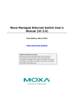
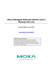
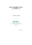
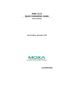
1
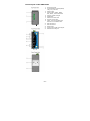
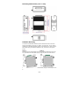
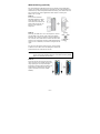
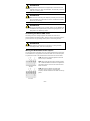
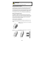
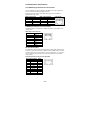
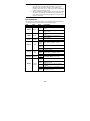
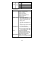
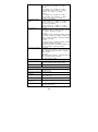
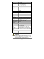
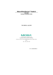
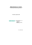
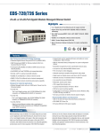
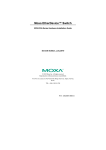
AWK-3131 Hardware Installation Guide Moxa AirWorks First Edition, February 2011 2011 Moxa Inc. All rights reserved. P/N: 1802031310010 Overview Moxa's new AWK-3131 3-in-1 industrial wireless AP/bridge/client meets the growing need for faster data transmission speeds and wider coverage by supporting IEEE 802.11n technology with a net data rate of up to 300 Mbps. The AWK-3131 combines two adjacent 20 MHz channels into a single 40 MHz channel to deliver a potent combination of greater reliability and more bandwidth. The two redundant DC power inputs increase the reliability of the power supply, and the AWK-3131 can be powered via PoE to make deployment easier. The AWK-3131 can operate on either the 2.4 or 5 GHz bands and is backward-compatible with existing 802.11a/b/g deployments to future-proof your wireless investments. Package Checklist Moxa’s AWK-3131 is shipped with the following items. If any of these items is missing or damaged, please contact your customer service representative for assistance. • • • • • • • • AWK-3131 2 dual-band omni-directional antennas (2dBi, RP-SMA, 2.4/5 GHz) Cable holder with one screw 3 protective caps DIN-rail kit Documentation and software CD Quick installation guide (printed) Warranty card Recommended SFP Accessories SFP-1G series • • • • • • • • SFP-1GSXLC: Small form factor pluggable transceiver with 1000BaseSX, LC, 0.5 km, 0 to 60°C SFP-1GSXLC-T: Small form factor pluggable transceiver with 1000BaseSX, LC, 0.5 km, -20 to 75°C SFP-1GLSXLC: Small form factor pluggable transceiver with 1000BaseLSX, LC, 2 km, 0 to 60°C SFP-1GLSXLC-T: Small form factor pluggable transceiver with 1000BaseLSX, LC, 2 km, -40 to 85°C SFP-1GLXLC: Small form factor pluggable transceiver with 1000BaseLX, LC, 10 km, 0 to 60°C SFP-1GLXLC-T: Small form factor pluggable transceiver with 1000BaseLX, LC, 10 km, -40 to 85°C SFP-1GLHLC: Small form factor pluggable transceiver with 1000BaseLH, LC, 30 km, 0 to 60°C SFP-1GLHLC-T: Small form factor pluggable transceiver with 1000BaseLH, LC, 30 km, -40 to 85°C -2- • • • • • • SFP-1GLHXLC: Small form factor pluggable transceiver with 1000BaseLHX, LC, 40 km, 0 to 60°C SFP-1GLHXLC-T: Small form factor pluggable transceiver with 1000BaseLHX, LC, 40 km, -40 to 85°C SFP-1GZXLC: Small form factor pluggable transceiver with 1000BaseZX, LC, 80 km, 0 to 60°C SFP-1GZXLC-T: Small form factor pluggable transceiver with 1000BaseZX, LC, 80 km, -40 to 85°C SFP-1GEZXLC: Small form factor pluggable transceiver with 1000BaseEZX, LC, 110 km, 0 to 60°C SFP-1GEZXLC-120: Small form factor pluggable transceiver with 1000BaseEZX, LC, 120 km, 0 to 60°C Installation and Configuration Before installing the AWK-3131, make sure that all items in the Package Checklist are in the box. In addition, you will need access to a notebook computer or PC equipped with an Ethernet port. The AWK-3131 has a default IP address that you must use when connecting to the device for the first time. Step 1: Select the power source The AWK-3131 can be powered by a DC power input or PoE (Power over Ethernet). The AWK-3131 will use whichever power source you choose. Step 2: Connect the AWK-3131 to a notebook or PC Since the AWK-3131 supports MDI/MDI-X auto-sensing, you can use either a straight-through cable or crossover cable to connect the AWK-3131 to a computer. If the LAN LED indicator on the AWK-3131 port lights up, it means the connection is established. Step 3: Set up the computer’s IP address Set an IP address on the same subnet as the AWK-3131. Since the AWK-3131’s default IP address is 192.168.127.253, and the subnet mask is 255.255.255.0, you should set the IP address of the computer to 192.168.127.xxx and subnet mask to 255.255.255.0. Step 4: Use the web-based manager to configure AWK-3131 Open your computer’s web browser and then type http://192.168.127.253 in the address field to access the homepage of the web-based management. Before the homepage opens, you will need to enter the user name and password. For first-time configuration, enter the default user name and password and then click on the Login button: User name: admin Password: root -3- ATTENTION For security reasons, we strongly recommend changing the password. To do so, select Maintenance Password, and then follow the on-screen instructions. Step 5: Select the operation mode for the AWK-3131 By default, the AWK-3131’s operation mode is set to AP. You can change the setting in Wireless Settings Basic Wireless Settings if you would like to use the Client mode. NOTE To make the change effective, you must click Save Configuration to save the change or the Save and Restart button to apply all changes. Step 6: Test communications We will describe two test methods. Use the first method if you are using only one AWK-3131, and use the second method if you are using two or more AWK-3131s. Testing method for one AWK-3131 If you are only using one AWK-3131, you will need a second notebook computer (B) equipped with a WLAN card. Configure the WLAN card to connect to the AWK-3131 (the default SSID is MOXA) and change the IP address of notebook B so that it is on the same subnet as the first notebook (A), which is connected to the AWK-3131. After configuring the WLAN card, establish a wireless connection with the AWK-3131 and open a DOS window on notebook B. At the prompt, type ping IP address of notebook A and then press the Enter key. A “Reply from IP address …” response means the communication was successful. A “Request timed out.” response means the communication failed. In this case, recheck the configuration to make sure the connections are correct. Testing method for two or more AWK-3131s If you have two or more AWK-3131s, you will need a second notebook computer (B) equipped with an Ethernet port. Use the default settings for the first AWK-3131 connected to notebook A, and change the second or third AWK-3131 connected to notebook B to Client mode and then configure the notebooks and AWK-3131s properly. After setting up the testing environment, open a DOS window on notebook B. At the prompt, type ping IP address of notebook A and then press Enter key. A “Reply from IP address …” response means the communication was successful. A “Request timed out.” response means the communication failed. In this case, recheck the configuration to make sure the connections are correct. -4- Panel Layout of the AWK-3131 1. 2. 3. 4. 5. 6. 7. 8. 9. 10. 11. 12. 13. 14. -5- Grounding screw Terminal block for PWR1,PWR2, relay, DI1, and DI2 Reset button System LEDs: PWR1, PWR2, PoE, FAULT, and STATE LEDs LEDs for signal strength WLAN LED Ethernet or Fiber LED RS-232 console port LANs: 10/100/1000 BaseT(X) RJ45 Port or 1000Base SFP Main Antenna A Main Antenna B Model name Screw hole for wall mounting Kit DIN-Rail mounting kit Mounting Dimensions (unit = mm) DIN-Rail Mounting The aluminum DIN-Rail attachment plate should be fixed to the back panel of the AWK-3131 when you take it out of the box. If you need to reattach the DIN-Rail attachment plate to the AWK-3131, make sure the stiff metal spring is situated towards the top, as shown in the figures below. STEP 1: STEP 2: Insert the top of the DIN-Rail into theThe DIN-Rail attachment unit will slot just below the stiff metal spring. snap into place as shown below. To remove the AWK-3131 from the DIN-Rail, simply reverse Steps 1 and 2. -6- Wall Mounting (optional) For transportation applications that require an EN 50155 certification report, we strongly recommend the purchase of the optional AWK-3131 wallmount kit, which has passed EN 50155 testing. This wallmount kit is also convenient for other applications that require mounting the AWK-3131 to a wall. STEP 1: Remove the aluminum DIN-Rail attachment plate from the AWK-3131, and then attach the wall mount plates with M3 screws, as shown in the adjacent diagrams. STEP 2: Mounting the AWK-3131 to a wall requires 3 screws. Use the AWK-3131 device, with wall mount plates attached, as a guide to mark the correct locations of the 3 screws. The heads of the screws should be less than 6.0 mm in diameter, and the shafts should be less than 3.5 mm in diameter, as shown in the figure at the right. Do not screw the screws in all the way—leave a space of about 2 mm to allow room for sliding the wall mount panel between the wall and the screws. NOTE Test the screw head and shank size by inserting the screw into one of the keyhole shaped apertures of the Wall Mounting Plates before it is screwed into the wall. STEP 3: Once the screws are fixed into the wall, insert the four screw heads through the large opening of the keyhole-shaped apertures, and then slide the AWK-3131 downwards, as indicated to the right. Tighten the three screws for added stability. -7- WARNING • • • • This equipment is intended to be used in a Restricted Access Location, such as a dedicated computer room. Access can only be gained by SERVICE PERSONS or by USERS who have been instructed about the fact that the metal chassis of the equipment is extremely hot and may cause burns. Service persons or users have to pay special attention and take special precaution before handling the equipment. Access is to be controlled through the use of a lock and key or a security identity system, controlled by the authority responsible for the location. Only authorized, well-trained professionals are allowed to access the restricted access location. External metal parts are hot!! Pay special attention or use special protection before handling. Wiring Requirements WARNING Safety First! Be sure to disconnect the power cord before installing and/or wiring your Moxa AWK-3131. WARNING Safety First! Calculate the maximum possible current in each power wire and common wire. Observe all electrical codes dictating the maximum current allowed for each wire size. If the current goes above the maximum ratings, the wiring could overheat, causing serious damage to your equipment. You should also pay attention to the following items: • • • • Use separate paths to route wiring for power and devices. If power wiring and device wiring paths must cross, make sure the wires are perpendicular at the intersection point. NOTE: Do not run signal or communications wiring and power wiring in the same wire conduit. To avoid interference, wires with different signal characteristics should be routed separately. You can use the type of signal transmitted through a wire to determine which wires should be kept separate. The rule of thumb is that wiring with similar electrical characteristics can be bundled together. Keep input wiring and output wiring separate. It is strongly advised that you label wiring to all devices in the system when necessary. -8- ATTENTION This product is intended to be supplied by a Listed Power Unit marked “Class 2” or “LPS” and rated O/P: 12 to 48 VDC, minimum 6 W (12 V to 48V), 25°C. ATTENTION Make sure the external power adaptor (includes power cords and plug assemblies) provided with the unit is certified and suitable for use in your country. ATTENTION Do not use the PoE Injector. Instead, please use an IEEE802.3af or IEEE802.3at compliant PSE (Power Sourcing Equipment) for PoE (Power over Ethernet) device. Grounding the Moxa AWK-3131 Grounding and wire routing help limit the effects of noise due to electromagnetic interference (EMI). Run the ground connection from the ground screw to the grounding surface prior to connecting devices. ATTENTION This product is intended to be mounted to a well-grounded mounting surface, such as a metal panel. Wiring the Redundant Power Inputs The top two pairs of contacts of the 10-contact terminal block connector on the AWK-3131’s top panel are used for the AWK-3131’s two DC inputs. Top and front views of the terminal block connector are shown below. STEP 1: Insert the negative/positive DC wires into the V-/V+ terminals. STEP 2: To keep the DC wires from pulling loose, use a small flat-blade screwdriver to tighten the wire-clamp screws on the front of the terminal block connector. STEP 3: Insert the plastic terminal block connector prongs into the terminal block receptor, which is located on the AWK-3131’s top panel. -9- ATTENTION Before connecting the AWK-3131 to the DC power inputs, make sure the DC power source voltage is stable. Wiring the Relay Contact The AWK-3131 has one relay output, which consists of the two contacts of the terminal block on the AWK-3131’s top panel. Refer to the previous section for detailed instructions on how to connect the wires to the terminal block connector, and how to attach the terminal block connector to the terminal block receptor. These relay contacts are used to indicate user-configured events. The two wires attached to the Relay contacts form an open circuit when a user-configured event is triggered. If a user-configured event does not occur, the Relay circuit will be closed. Wiring the Digital Inputs The AWK-3131 has two sets of digital input—DI1 and DI2. Each DI comprises two contacts of the 10-pin terminal block connector on the AWK-3131’s top panel. You can refer to the “Wiring the Redundant Power Inputs” section for detailed instructions on how to connect the wires to the terminal block connector, and how to attach the terminal block connector to the terminal block receptor. Cable Holder Installation You can attach the cable holder to the bottom of the AWK-3131. This helps to keep cabling neat and avoid accidents that result from untidy cables. STEP 1: Screw the cable holder onto the bottom of the AWK-3131. STEP 2: After mounting the AWK-3131 and plugging in the LAN cable, tighten the cable along the device and wall. - 10 - Communication Connections 10/100BaseT(X) Ethernet Port Connection The 10/100BaseT(X) ports located on the AWK-3131’s front panel are used to connect to Ethernet-enabled devices. Below we show pinouts for both MDI (NIC-type) ports and MDI-X (HUB/Switch-type) ports. MDI Port Pinouts Pin Signal 1 Tx+ 2 Tx3 Rx+ 6 Rx- MDI-X Port Pinouts Pin Signal 1 Rx+ 2 Rx3 Tx+ 6 Tx- 8-pin RJ45 1000BaseT Ethernet Port Connection 1000BaseT data is transmitted on differential TRD+/- signal pairs over copper wires. MDI/MDI-X Port Pinouts Pin Signal 1 TRD(0)+ 2 TRD(0)3 TRD(1)+ 4 TRD(2)+ 5 TRD(2)6 TRD(1)7 TRD(3)+ 8 TRD(3)- RS-232 Connection The AWK-3131 has one RS-232 (8-pin RJ45) console port located on the front panel. Use either an RJ45-to-DB9 or RJ45-to-DB25 cable to connect the Moxa AWK-3131’s console port to your PC’s COM port. You may then use a console terminal program to access the AWK-3131 for console configuration. Console Pinouts for 10-pin or 8-pin RJ45 10-Pin Description 8-Pin 1 ----2 DSR 1 3 RTS 2 4 GND 3 5 TxD 4 6 RxD 5 7 DCD 6 8 CTS 7 9 DTR 8 10 ----- - 11 - NOTE 1. 2. The pin numbers for male DB9 and DB25 connectors, and hole numbers for female DB9 and DB25 connectors are labeled on the connector. However, the numbers are typically quite small, so you may need to use a magnifying glass to see the numbers clearly. The pin numbers for both 8-pin and 10-pin RJ45 connectors (and ports) are typically not labeled on the connector (or port). Refer to the Pinout diagram above to see how RJ45 pins are numbered. LED Indicators The front panel of the Moxa AWK-3131 contains several LED indicators. The function of each LED is described in the table below. LED Color State Description Front Panel LED Indicators (System) Power is being supplied from power On input 1. PWR1 Green Power is not being supplied from Off power input 1. Power is being supplied from power On input 2. PWR2 Green Power is not being supplied from Off power input 2. On Power is being supplied via PoE. PoE Amber Off Power is not being supplied via PoE. Cannot get an IP address from the Blink DHCP server (interval: 1 sec) (slow) FAULT Red Blink IP address conflict (interval: 0.5 sec) (fast) Off Error condition does not exist. Green Software Ready Green/ Green The AWK has been located by AWK STATE Red Blink Search Utility. (interval: 1sec) Red Booting error condition On Signal level SIGNAL Green (for Client/Slave mode only) (5 LEDs) Off Amber WLAN functions in AP/Bridge mode. On Amber WLAN’s data communication is run in Blink AP/Bridge mode Green/ WLAN WLAN is not in use or not working Amber Off properly Green On WLAN functions in Client/Slave mode. Green WLAN’s data communication is run in Blink Client/Slave mode - 12 - LAN Green/ Amber Amber Amber Blinking Amber Off Green Green Blinking Green Off LAN port’s 10/100 Mbps link is active. Data is being transmitted at 10/100 Mbps LAN port’s 10/100 Mbps link is inactive LAN port’s 1000 Mbps link is active. Data is being transmitted at 1000 Mbps LAN port’s 1000 Mbps link is inactive Specifications WLAN Interface Standards: Spread Spectrum and Modulation (typical): Operating Channels (central frequency): Security: Transmission Rates: IEEE 802.11a/b/g/n for Wireless LAN IEEE 802.11i for Wireless Security IEEE 802.3 for 10BaseT IEEE802.3u for 100BaseTX IEEE 802.3ab for 1000BaseT IEEE 802.3af for Power-over-Ethernet IEEE 802.1D for Spanning Tree Protocol IEEE 802.1w for Rapid STP IEEE 802.1Q VLAN • 2 x 2 (MIMO) with two spatial streams • DSSS with DBPSK, DQPSK, CCK • OFDM with BPSK, QPSK, 16QAM, 64QAM • 802.11b: CCK @ 11/5.5 Mbps, DQPSK @ 2 Mbps, DBPSK @ 11 Mbps • 802.11a/g: 64QAM @ 54/48 Mbps, 16QAM @ 36/24 Mbps, QPSK @ 18/12 Mbps, BPSK @ 9/6 Mbps • 802.11n: 64QAM @ 300 Mbps to BPSK @ 6.5 Mbps (multiple rates supported) US: 2.412 to 2.462 GHz (11 channels) 5.18 to 5.24 GHz (4 channels) EU: 2.412 to 2.472 GHz (13 channels) 5.18 to 5.24 GHz (4 channels) JP: 2.412 to 2.472 GHz (13 channels, OFDM) 2.412 to 2.484 GHz (14 channels, DSSS) 5.18 to 5.24 GHz (4 channels for W52) • SSID broadcast enable/disable • Firewall for MAC/IP/Protocol/Port-based filtering • 64-bit and 128-bit WEP encryption, WPA /WPA2-Personal and Enterprise (IEEE 802.1X/RADIUS, TKIP and AES) 802.11b: 1, 2, 5.5, 11 Mbps 802.11a/g: 6, 9, 12, 18, 24, 36, 48, 54 Mbps 802.11n: 6 to 300 Mbps (multiple rates supported) - 13 - TX Transmit Power: TX Transmit Power MIMO: RX Sensitivity: RX Sensitivity MIMO: 802.11b: 1 to 11 Mbps: Typ. 18 dBm (± 1.5 dBm) 802.11g: 6 to 24 Mbps: Typ. 18 dBm (± 1.5 dBm) 36 to 48 Mbps: Typ. 17 dBm (± 1.5 dBm) 54 Mbps: Typ. 15 dBm (± 1.5 dBm) 802.11a: 6 to 24 Mbps: Typ. 17 dBm (± 1.5 dBm) 36 to 48 Mbps: Typ. 16 dBm (± 1.5 dBm) 54 Mbps: Typ. 14 dBm (± 1.5 dBm) 802.11a/n (20/40 MHz): MCS15 20 MHz: Typ. 13 dBm (± 1.5 dBm) MCS15 40 MHz: Typ. 12 dBm (± 1.5 dBm) 802.11g/n (20/40 MHz): MCS15 20 MHz: Typ. 14 dBm (± 1.5 dBm) MCS15 40 MHz: Typ. 13 dBm (± -1.5 dBm) 802.11b: -92 dBm @ 1 Mbps, -90 dBm @ 2 Mbps, -88 dBm @ 5.5 Mbps, -84 dBm @ 11 Mbps 802.11g: -87 dBm @ 6 Mbps, -86 dBm @ 9 Mbps, -85 dBm @ 12 Mbps, -82 dBm @ 18 Mbps, -80 dBm @ 24 Mbps, -76 dBm @ 36 Mbps, -72 dBm @ 48 Mbps, -70 dBm @ 54 Mbps 802.11a: -87 dBm @ 6 Mbps, -86 dBm @ 9 Mbps, -85 dBm @ 12 Mbps, -82 dBm @ 18 Mbps, -80 dBm @ 24 Mbps, -76 dBm @ 36 Mbps, -72 dBm @ 48 Mbps, -70 dBm @ 54 Mbps 802.11a/n: -68 dBm @ MCS15 40 MHz, -70 dBm @ MCS7 40 MHz, -69 dBm @ MCS15 20 MHz, -71 dBm @ MCS7 20 MHz 802.11g/n: -68 dBm @ MCS15 40 MHz, -70 dBm @ MCS7 40 MHz, -69 dBm @ MCS15 20 MHz, -71 dBm @ MCS7 20 MHz Protocol Support General Protocols: AP-only Protocols: Proxy ARP, DNS, HTTP, HTTPS, IP, ICMP, SNTP, TCP, UDP, RADIUS, SNMP, PPPoE, DHCP ARP, BOOTP, DHCP, STP/RSTP (IEEE 802.1D/w) Interface Default Antennas: 2 dual-band omni-directional antennas, 2 dBi, RP-SMA (male) Connector for External RP-SMA (female) Antennas: LAN Ports: 1, 10/100/1000BaseT(X), auto negotiation speed (RJ45-type) Fiber Ports: 1, 1000BaseSFP slot Console for External Antenna: LED Indicators: RS-232 (RJ45-type) PWR1, PWR2, PoE, FAULT, STATE, signal strength, WLAN, LAN - 14 - Alarm Contact: Digital Inputs: 1 relay output with current carrying capacity of 1 A @ 24 VDC 2 electrically isolated inputs • +13 to +30 V for state “1” • +3 to -30 V for state “0” • Max. input current: 8 mA Physical Characteristics Housing: Metal, IP30 protection Weight: 970 g Dimensions: 53.6 x 135 x 105 mm (2.11 x 5.31 x 4.13 in) Installation: DIN-Rail mounting (standard), wall mounting (optional) Environmental Limits Operating Temperature: Standard Models: 0 to 60°C (32 to 140°F) Wide Temp. Models: -40 to 75°C (-40 to 167°F) Storage Temperature: -40 to 85°C (-40 to 185°F) Ambient Relative Humidity: 5% to 95% (non-condensing) Power Requirements Input Voltage: Connector: 12 to 48 VDC, redundant dual DC power inputs or 48 VDC Power-over-Ethernet (IEEE 802.3af compliant) 10-pin removable terminal block Power Consumption: 12 to 48 VDC, 700mA (max.) Reverse Polarity Protection: Present Standards and Certifications Safety: UL 60950-1, EN 60950-1 EMC: EN 301 489-1/17, FCC Part 15 Subpart B Class B, EN 55022/55024 Radio: EN 300 328, EN 301 893, DSPR (Japan) Rail Traffic: EN 50155, EN 50121-1/4 (Environmental) Note: Please check Moxa’s website for the most up-to-date certification status. Warranty Warranty Period: 5 years Details: See www.moxa.com/warranty ATTENTION The AWK-3131 is NOT a portable mobile device and should be located at least 20 cm away from the human body. The AWK-3131 is NOT designed for the general public. To deploy AWK-3131s and establish a wireless network safely, a well-trained technician is required for installation. - 15 - ATTENTION Use the antennas correctly: The 2.4 GHz antennas are needed when the AWK-3131 operates in IEEE 802.11b/g/n. The 5 GHz antennas are needed for IEEE802.11a/n. Make sure your antenna installation is within a safety area, which is covered by a lightning protection or surge arrest system. Technical Support Contact Information www.moxa.com/support Moxa Americas: Toll-free: 1-888-669-2872 Tel: 1-714-528-6777 Fax: 1-714-528-6778 Moxa China (Shanghai office): Toll-free: 800-820-5036 Tel: +86-21-5258-9955 Fax: +86-21-5258-5505 Moxa Europe: Tel: +49-89-3 70 03 99-0 Fax: +49-89-3 70 03 99-99 Moxa Asia-Pacific: Tel: +886-2-8919-1230 Fax: +886-2-8919-1231 - 16 -