1
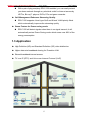
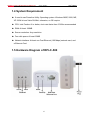
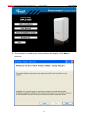
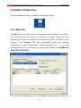
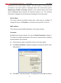
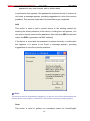
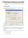
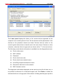
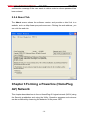
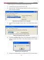
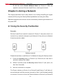
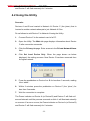
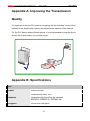
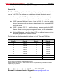
500Mbps Powerline Gigabit Ethernet Adapter RPLC-500 User Manual 500Mbps Powerline Gigabit Ethernet Adapter KIT - RPLC-500KIT- User’s Manual Contents PACKAGE CONTENTS ......................................................................................................... 3 CHAPTER 1 INTRODUCTION TO HARDWARE .............................................................. 4 1.1 EXPANDING YOUR NETWORK WITH RPLC-500 .................................................... 4 1.2 KEY FEATURES ................................................................................................. 4 1.3 APPLICATION .................................................................................................... 5 1.4 SYSTEM REQUIREMENT ..................................................................................... 6 1.5 HARDWARE DIAGRAM OF RPLC-500 ................................................................. 6 1.5.1 LED .................................................................................................. 7 1.5.2 Powerline Adapter’s Button and Connector ................................. 7 CHAPTER 2 INTRODUCTION TO UTILITY ............................................................. 8 2.1 UTILITY INSTALLATION............................................................................... 8 2.2 UTILITY INTRODUCTION ........................................................................... 12 2.2.1 Main Tab ........................................................................................ 12 2.2.2 Privacy Tab.................................................................................... 15 2.2.3 Diagnostics Tab ............................................................................ 16 2.2.4 About Tab ...................................................................................... 18 CHAPTER 3 FORMING A POWERLINE (HOMEPLUG AV) NETWORK ................ 18 3.1 USING THE SECURITY PUSHBUTTON ......................................................... 19 3.2 USING THE UTILITY ................................................................................. 19 CHAPTER 4 JOINING A NETWORK...................................................................... 21 4.1 USING THE SECURITY PUSHBUTTON ......................................................... 21 4.2 USING THE UTILITY ................................................................................. 22 APPENDIX A: IMPROVING THE TRANSMISSION QUALITY ............................... 23 APPENDIX B: SPECIFICATIONS .......................................................................... 23 APPENDIX C: ACRONYMS AND ABBREVIATIONS ............................................. 25 APPENDIX D: RPLC-500 QOS SUPPORT ............................................................ 25 -2- 500Mbps Powerline Gigabit Ethernet Adapter KIT - RPLC-500KIT- User’s Manual Package Contents The following items should be found in your package: 2x Rosewill RPLC-500 500Mbps Powerline Gigabit Ethernet Adapter 2x RJ45 Ethernet Cable 1x Quick Installation Guide 1x Resource CD for RPLC-500, including: Rosewill Powerline Utility Quick Installation Guide User Guide Note: Make sure that the package contains the above items. If any of the listed items are damaged or missing, please contact with your distributor. -3- 500Mbps Powerline Gigabit Ethernet Adapter KIT - RPLC-500KIT- User’s Manual Chapter 1 Introduction to Hardware Thank you for purchasing Rosewill‟s RPLC-500 Homeplug AV compliant Powerline Adapter. The RPLC-500 adapter can transmit data up to 500mbps via household‟s power outlet. RPLC-500 can help you to establish a high-speed network that supports video, voice and data without wiring and drilling. It is suitable for using in a wide range of both residential (at home) and commercial (offices, apartments, hotels, warehouses) network applications. 1.1 Expanding your Network with RPLC-500 The RPLC-500 plugs into an power outlet to extend cable or DSL modem connection or your current Ethernet Network to almost any power outlet in your home with any new cabling.* Devices can securely communicate with each other via the 128-bit Advanced Encryption Standard (AES) through RPLC-500 at a high speed transfer rate of 500Mbps and Gigabit LAN support. Note: Powerline Technology has certain limitations. 1. The best performance for Powerline Data transmission will be under one power circuit 2. Performance may be decreased under different circuits but within one Electricity Meter due to the drop-off via hardware. 1.2 Key Features Plug and Play with Quick and Easy Installation Installation requires no new wiring Every power socket becomes a connection node in the household. RPLC-500 supports connection for a total of 8 nodes. Plug-and-play to your routers, computers and other network devices. Power up your Network with Ultra fast speed Physical data rate is up to 500Mbps. Ethernet Speed is up to 1000Mbps Enjoy Stable HD Videos and Gaming -4- 500Mbps Powerline Gigabit Ethernet Adapter KIT - RPLC-500KIT- User’s Manual With a pair of plug-and-play RPLC-500 installed, you can easily extend your home network through any electrical outlet for Internet access by HDTVs, Blu-ray™ players, DVRs, PCs and game consoles. QoS Management Enhances Streaming Quality RPLC-500 supports 4-level type QoS and 8-level VLAN priority fields which automatically improves the streaming quality Green Feature for Power saving mode RPLC-500 will detect signals when there is no signal transmit, it will automatically enters Power Saving mode which saves near 80% of the energy consumption. 1.3 Application High Definition (HD) and Standard Definition (SD) video distribution Higher data rate broadband sharing for Powerline LAN Shared broadband internet access TV over IP (IPTV) and Voice over Internet Protocol (VoIP) -5- 500Mbps Powerline Gigabit Ethernet Adapter KIT - RPLC-500KIT- User’s Manual 1.4 System Requirement If need to use Powerline Utility: Operating system: Windows 98SE, 2000, ME, XP 32/64 bit and Vista 32/64bit, otherwise, no OS require CPU: Intel Pentium III or better, clock rate faster than 2.0GHz recommended RAM: At least 128MB Screen resolution: Any resolution Free disk space: At least 20MB Network interface: At least one Fast Ethernet (100 Mbps) network card, and a Ethernet Cord 1.5 Hardware Diagram of RPLC-500 -6- 500Mbps Powerline Gigabit Ethernet Adapter KIT - RPLC-500KIT- User’s Manual 1.5.1 LED LED Color Behavior Description Green On System runs normally. Green Blink System is resetting. System is in the process of password synchronization. System is in Power Saving mode - Off The PLC adapter is powered off. Green On Ethernet connection has established. Blink Data is being transmitted. Off No Ethernet connection. On The PLC adapter has connected to the powerline network. The Data LED color may vary according to the Data Transmit Quality. (Power) (Ethernet) Green/Orange/Red (Data) Green: Data Transmit Quality Excellent Orange: Data Transmit Quality Average Red: Data Transmit Quality Poor - Off The PLC adapter does not connect to the powerline network. 1.5.2 Powerline Adapter’s Button and Connector Reset: Pressing and holding the Button for between 10 seconds and 15 seconds makes the adapter restore the factory default settings. Security: Pressing and holding the button for less than 3 seconds makes the adapter a member of the existing Powerline Network. Ethernet Port (RJ45 Port): The Ethernet port connects to an Ethernet network cable. The other end of the cable connects to your computer or other Ethernet-enabled network device. Connecting to the router/modem: Insert One end of the RJ45 Cable (Recommend using Cat 5E cable or above) to this port, and the other end to the router or modem. Then plug into the electrical outlet. -7- 500Mbps Powerline Gigabit Ethernet Adapter KIT - RPLC-500KIT- User’s Manual Connecting to PC / Smart TV / NB / Blu-ray Player / Media Player / IP Phone: Insert One end of the RJ45 Cable (Recommend using Cat 5E cable or above) to this port, and the other end to the other devices. Then plug into the electrical outlet. Chapter 2 Introduction to Utility Note: Before installing the PLC utility software, make sure that there is no any other powerline utility installed on your computer. If there is another utility installed, please uninstall it and restart your computer. 2.1 Utility Installation Please follow the steps below to install the utility. 1. Please insert the utility CD into the computer‟s CD-ROM drive. Select the Utility Installation from the Wizard Page. -8- 500Mbps Powerline Gigabit Ethernet Adapter KIT - RPLC-500KIT- User’s Manual 2. The window for installing the utility software will display. Click Next to continue. -9- 500Mbps Powerline Gigabit Ethernet Adapter KIT - RPLC-500KIT- User’s Manual 3. Select I Agree, and then Next to continue. 4. You can choose your own destination folder to install or click Browse… to select the installation folder, and then click Next to continue.. -10- 500Mbps Powerline Gigabit Ethernet Adapter KIT - RPLC-500KIT- User’s Manual 5. You can choose your own destination folder to install or click Browse… to select the installation folder, and then click Next to continue. -11- 500Mbps Powerline Gigabit Ethernet Adapter KIT - RPLC-500KIT- User’s Manual 2.2 Utility Introduction Click the desktop icon below to enter the configuration page. 2.2.1 Main Tab The Main screen provides a list of all powerline devices logically connected to the computer when the utility is running.The top panel shows the local HomePlugAV devices connected to the network interface card (NIC) of the computer. Click Connect. The utility automatically scans the powerline periodically for other HomePlugAV devices connected to it. If no local HomePlugAV device is discovered, the status bar displays NO HOMEPLUG ADAPTERS DETECTED. The lower panel displays all the HomePlugAV remote devices, which are -12- 500Mbps Powerline Gigabit Ethernet Adapter KIT - RPLC-500KIT- User’s Manual discovered in the current logical network. The total number of remote devices connected in the same network is displayed above the remote device panel. Network type (Public or Private) depends on the network status of the local device. Autoscan shows whether the autoscan function is on. The following information is displayed for all the devices that appear in the lower panel. Device Name This column shows the default device name, which may be modified. To change the name, click Rename, or click the name and edit it in the list. MAC Address This column shows the MAC addresses of the remote devices. Password By default, this column is blank. You can click Enter Password to change it. The steps for setting the password of the device (required when creating a private network) are as follows: Click the device name to select the device in the lower panel. Click Enter Password. A dialog box appears, showing the device name and password. Click OK to verify the password. The password field accepts the device -13- 500Mbps Powerline Gigabit Ethernet Adapter KIT - RPLC-500KIT- User’s Manual password in any case formats, with or without dash. A confirmation box appears if the password is entered correctly. If a device is not found, a message appears, providing suggestions to solve the common problems. This process might take a few seconds to get completed. Add This button is used to add a remote device to the existing network by entering the device password of the device. A dialog box will appears. You can enter a device name and the password. (Also refers as DEK on the back Label, this DEK is generates via MAC address) If the device is found and the password is entered correctly, a confirmation box appears. If a device is not found, a message appears, providing suggestions to solve the common problems. Note: The device must be in the powerline (plugged in), so that you can confirm the password and add the device to the network. If the device is not located, a warning message appears. Scan This button is used to perform an immediate search for HomePlugAV -14- 500Mbps Powerline Gigabit Ethernet Adapter KIT - RPLC-500KIT- User’s Manual devices connected to the powerline network. By default, the utility automatically scans every a few seconds and updates the displayed information. 2.2.2 Privacy Tab In the Privacy screen, you can maintain security for the logical network and select the device included in the network. All HomePlugAV devices are loaded using a default logical network (network name), which is normally “HomePlugAV”. In the Privacy screen, you can modify a private network by changing the network names and the passwords of the devices. You can always reset to the HomePlugAV network (Public) by entering “HomePlugAV” as the network name or by clicking on the Use Default button. Note: If the network name changes to anything other than HomePlugAV, the network type in the main screen is displayed as Private. Set Local Device Only -15- 500Mbps Powerline Gigabit Ethernet Adapter KIT - RPLC-500KIT- User’s Manual This button is used to change the network name and password of the local device. If a new network password is entered, all the devices appeared in the main panel prior to this are no longer present in the new network, effectively making the local devices not to communicate to the devices which are in the old logical network. Click Set Local Device Only, the devices previously set up with the same logical network (same network name) appears in the device list. Set All Devices This button is used to change the logical network of all devices that appear in the main panel. If these devices whose passwords have been entered for the same logical network, a dialog box appears, indicating the success of this operation. For the devices whose passwords are not entered, this operation will fail and it will report a failure message. 2.2.3 Diagnostics Tab The Diagnostics screen shows the system information and history of all remote devices appeared over a period of time. The Upper panel shows technical data concerning software and hardware on the host computer that are used to communicate through HomePlug on the powerline network. It includes the following: Operating system platform/version Host network name User name MAC address of all NICs (Network interface card) connected to the host Identify versions of all driver DLLs and libraries used (NDIS) and optionally HomePlug chipset manufacturer name (Turbo Only devices) MAC firmware version (Turbo Only devices) MAC addresses of all devices connected locally to the host Version of the configuration utility Vendor name -16- 500Mbps Powerline Gigabit Ethernet Adapter KIT - RPLC-500KIT- User’s Manual The Lower panel displays the history of all remote devices appeared on the computer over a certain period of time. All the devices and the parameters of the devices on the powerline network are listed. Devices that are active on the current logical network show a transfer rate in the rate column. Devices on other networks, or devices that no longer exist are shown with a “?” in the rate column. The following remote device information is available from the diagnostics screen: Device alias name MAC address Password Device last known rate Device last known network name HomePlug chipset manufacturer name Date device last seen on the network MAC firmware version The diagnostics information displayed can be saved to a text file for later use, or be printed for reference for a technical support call. Click Delete to delete the devices which are no longer part of the network. A dialog window pops up with a -17- 500Mbps Powerline Gigabit Ethernet Adapter KIT - RPLC-500KIT- User’s Manual confirmation message if the user wants to delete a device whose password has been entered. 2.2.4 About Tab The About screen shows the software version and provides a html link to a website, such as http://www.qua.qualcomm.com. Clicking the web address, you can visit the web site. Chapter 3 Forming a Powerline (HomePlug AV) Network This chapter describes how to form a HomePlug AV logical network (AVLN) using the Security pushbutton and using the Utility. Operation progress and outcome can be monitored by observing the behavior of the power LED. -18- 500Mbps Powerline Gigabit Ethernet Adapter KIT - RPLC-500KIT- User’s Manual 3.1 Using the Security Pushbutton Scenario: Devices A and B with different NMK (Network Membership Key used to authenticate/access) values are connected to the same powerline. Users want to use them to form a logical network. Forming a HomePlug AV logical network Please follow below steps to form a logical network using the Security button: 1. Press the Security button on Device A for less than 3 seconds. 2. Press the Security button on Device B for less than 3 seconds. The button on B must be pressed within 2 minutes 3. Wait for connection to complete. The Power indicator on both devices will flash evenly at 1 second interval until the operation succeeds or fails. The Power indicator will illuminate steadily on successful completion. If an error occurs, the Power indicator on both devices will flash unevenly for 2 minutes. 3.2 Using the Utility Scenario: Devices A and B are located in different networks. Users want to use them to form a logical network. In this case, using the Security pushbutton cannot pair Devices A and B. Users can only use the Utility to form a logical network. -19- 500Mbps Powerline Gigabit Ethernet Adapter KIT - RPLC-500KIT- User’s Manual Please follow below to form a logical network using the Utility: 1. Connect Device A to the network card of a PC. 2. Open the Utility. The Main tab page displays information about Device A after connection succeeds. Search for Local device on your computer 3. Click the Privacy tab page. Enter a name in the Private Network Name field. Setting the network name for your PLC 4. Click Set Local Device Only. When the following page is displayed, the setting succeeds. Now Device A has been removed from its logical network. Network name setting success 5. Repeat the procedures above to configure Device B. Configure Device -20- 500Mbps Powerline Gigabit Ethernet Adapter KIT - RPLC-500KIT- User’s Manual B with the same Private Network Name as Device A. After the operation success, Devices A and B form a new logical network. Chapter 4 Joining a Network This chapter describes how to add a device to an existing HomePlug AV logical network (AVLN) using the Security/Reset pushbutton and using the Utility. Operation progress and outcome can be monitored by observing the behavior of the power LED. 4.1 Using the Security Pushbutton Scenario: Devices A and B are located in network N. Device C (the joiner) that is not located in any networks attempts to join Network N. Any devices on Network N can become the „adder‟. Joining a network Please follow below to add Device C to Network N using the Security button: 1. Press the Security button on Device A (or Device B) for less than 3 seconds, making it the „adder‟. 2. Within 2 minutes, press the Security button Device C (the „joiner‟) for less than 3 seconds. 3. Wait for connection to complete. The Power indicator on Device A (or Device B) and Device C will flash at 1 second intervals until the process succeeds or fails. It will illuminate steadily on success. If an error occurs, the Power indicator on Device A (or Device B) -21- 500Mbps Powerline Gigabit Ethernet Adapter KIT - RPLC-500KIT- User’s Manual and Device C will flash unevenly for 2 minutes. 4.2 Using the Utility Scenario: Devices A and B are located in Network N. Device C (the joiner) that is located in another network attempts to join Network N. See Do as follows to add Device C to Network N using the Utility: 1. Connect Device C to the network card of a PC. 2. Open the Utility. The Main tab page displays information about Device C after connection succeeds. 3. Click the Privacy tab page. Enter a name in the Private Network Name field. 4. Click Set Local Device Only. When the page shown as below displayed, the setting success. Now Device C has been removed from its logical network. 5. Press the pushbutton on Device A or B for less than 3 seconds, making it the „adder‟. 6. Within 2 minutes, press the pushbutton on Device C (the „joiner‟) for less than 3 seconds. 7. Wait for connection to complete. The Power indicator on Device A (or Device B) and Device C will flash at 1 second intervals until the process succeeds or fails. It will illuminate steadily on success. If an error occurs, the Power indicator on Device A (or Device B) and Device C will flash unevenly for 2 minutes. -22- 500Mbps Powerline Gigabit Ethernet Adapter KIT - RPLC-500KIT- User’s Manual Appendix A: Improving the Transmission Quality It is important to use the PLC product complying with the following "correct rules", because it can significantly improve the transmission capacity of the network. For the PLC device without female socket, it is recommended to plug the device directly into a wall socket, not to power stripe. × √ Appendix B: Specifications Spec Chipset Atheros AR7400 Standards Compliant with IEEE 1901 Compatible with HomePlug AV standard IEEE802.3, IEEE802.3u, IEEE802.3ab Encryption 128-bit AES Encryption -23- 500Mbps Powerline Gigabit Ethernet Adapter KIT - RPLC-500KIT- User’s Manual Ports 10/100/1000Mbps Ethernet port LEDs Power, Ethernet, Data Powerline Speeds Up to 500Mbps Powerline Range Up to 300 meters over Electricity line Maximum PLC support Capable of extending up to total of 8 Powerline adapters in one environment Connection Type RJ45 Connection Speeds 10/100/1000M Kit Type Double Frequency Band 2 MHz ~ 67.5 MHz Power Consumption <4.0W Operation Mode 2.78W Idle Mode 0.97W Standby Mode QoS Support ToS Support up to 4-level type QoS Support up to 8-level VLAN priority field IGMP snooping for multicast to multiple unicast mapping System Requirement Deployment requirements: Devices with 10/100 or 10/100/1000 Mbps Ethernet port Operates system not require. Utility software OS support: Microsoft Windows 2000/XP/Vista/7 Dimensions 3.54 x 2.17 x 1.41 in (90 x 55 x 36 mm) (1 Powerline adapter) Weight 0.24 lbs. (108 g) (1 Powerline adapter) Temperature 0°C ~ 40°C Humidity 10% ~ 90% Non-condensing -24- 500Mbps Powerline Gigabit Ethernet Adapter KIT - RPLC-500KIT- User’s Manual Appendix C: Acronyms and Abbreviations AVLN AV In-home Logical Network, the AVLAN is the set of STAs that possess the same network membership key. Every AVLN is managed by a single CCo. CCo Central Coordinator CSMA/CA Carrier Sense Multiple Access / Collision Avoidance DAK Device Access Key DM Device Manager IGMP Internet Group Management Protocol NEK Network Encryption Key NID Network ID (Identification) NMK Network Membership Key PLC Powerline Communication PIB Parameter Information Block STA Station, a STA in the network with a connection to the powerline and being able to source or sink traffic TDMA Time Division Multiple Access TEI Terminal Equipment Identifier TOS Type Of Service VLAN Virtual Local Area Network Appendix D: RPLC-500 QoS Support RPLC-500 allows for 4 levels of Channel Access Priority (CAP (0 – 3)). The 8 levels of VLAN Ethernet tags must be mapped to the 4 levels of CAP priority, where CAP 3 is the highest priority and CAP 0 is the lowest. CAP 3 priority might be used for voice and network management frames, and CAP 2 is used for -25- 500Mbps Powerline Gigabit Ethernet Adapter KIT - RPLC-500KIT- User’s Manual streaming video and music while CAP 1 and CAP 0 are used for data. Default CAP The „Default CAP‟ group allows for default priority mapping of packets that do not have a VLAN TAG. The settings are available for Unicast (directed to a host). Unicast - (default CAP 1) - sets the default channel access priority for unicast frames not matching any other classification or mapping. IGMP managed Multicast Stream (Fixed to CAP 2) - sets the default channel access priority for stream data belonging to a snooped IGMP multicast group. IGMP - (default CAP 3) - sets the channel access priority for IGMP frames - these are the group management frames, not the stream data. Multicast/Broadcast - sets the default CAP for multicast frames not in a snooped group and for broadcast frames. The following are the factory default settings for VLAN Tags and TOS Bits: VLAN Tag User Priority Default CAP Priority TOS Bit User Priority Default CAP Priority 0 CAP1 0 CAP1 1 CAP0 1 CAP0 2 CAP0 2 CAP0 3 CAP1 3 CAP1 4 CAP2 4 CAP2 5 CAP2 5 CAP2 6 CAP3 6 CAP3 7 CAP3 7 CAP3 Thank you for purchasing a quality Rosewill Product. Please register your product at: www.rosewill.com for complete warranty information and future support for your product. Rosewill Customer Service Hotline: 1-800-575-9885 Rosewill Customer Service Support: [email protected] -26- 500Mbps Powerline Gigabit Ethernet Adapter KIT - RPLC-500KIT- User’s Manual COPYRIGHT & TRADEMARKS Specifications are subject to change without notice. is a registered trademark of Rosewill Inc. Other brands and product names are trademarks or registered trademarks of their respective holders. No part of the specifications may be reproduced in any form or by any means or used to make any derivative such as translation, transformation, or adaptation without permission from Rosewill Inc. Copyright © 2010 Rosewill Inc. All rights reserved. http://www.rosewill.com Safety Warning This device is intended for connection to the AC powerline. For installation instructions, please refer to the installation section of this guide. The following precautions should be taken when using this product. Read all instructions before installing and operating this product. Follow all warnings and instructions marked on the product. Unplug the device from the wall outlet before cleaning. Use a damp cloth for cleaning. Do not use liquid cleaners or aerosol cleaners. Do not operate this product near water. This product should never be placed near or over a radiator or heat register. Do not use an extension cord between the device and the AC power source. Only a qualified technician should service this product. Opening or removing covers may result in exposure to dangerous voltage points or other risks. Do not plug the device into a power strip or surge protector because these devices may consist of filter and impair signal. Avoid plugging the device right next to noisy sources such as cell phone charger, Halogen light, noisy desktop computer, vacuum cleaner, etc. These cases result in poor transmission speed. Unplug the device from the wall outlet and refer the product to qualified service personnel for the following conditions: If liquid has been spilled into the product If the product has been exposed to rain or water If the product does not operate normally when the operating instructions are followed If the product exhibits a distinct change in performance Your product is marked with this symbol, which is known as the WEEE mark. WEEE stands for Waste Electronics and Electrical Equipment. It means that used electrical and electronic products should not be mixed with general waste. Used electrical and electronic equipment should be treated separately. -27-