1
Declaration of Conformity
FCC Warning
Manufacturer: InFocus Corporation, 13190 SW 68th Parkway, Portland, Oregon
97223-8368 USA
This device complies with part 15 of the FCC Rules. Operation is subject to the following
two conditions: (1) This device may not cause harmful interference, and (2) this device
must accept any interference received, including interference that may cause
undesired operation.
Note: This equipment has been tested and found to comply with the limits for a Class B
digital device, pursuant to part 15 of the FCC Rules. These limits are designed to
provide reasonable protection against harmful interference in a residential installation.
This equipment generates, uses and can radiate radio frequency energy and, if not
installed and used in accordance with the instructions, may cause harmful interference
to radio communications. However, there is no guarantee that interference will not
occur in a particular installation. If this equipment does cause harmful interference to
radio or television reception, which can be determined by turning the equipment off
and on, the user is encouraged to try to correct the interference by one or more of the
following measures:
--Reorient or relocate the receiving antenna.
--Increase the separation between the equipment and receiver.
--Connect the equipment into an outlet on a circuit different from that to which the
receiver is connected.
--Consult the dealer or an experienced radio/TV technician for help.
Changes or modifications not expressly approved by InFocus Corporation may void
authority to operate the equipment.
We declare under our sole responsibility that this projector conforms to the
following directives and norms:
EMC Directive 2004/108/EC
ErP Directive 2009/125/EC
EMC: EN 55022: 2010
EN 55024: 2010
EN 61000-3-2: 2006+A2:2009
EN 61000-3-3:2008
Low Voltage Directive 2006/95/EC
Safety: IEC 60950-1:2005; EN 60950-1:2006+A12:2011
Trademarks
Apple, Macintosh, and PowerBook are trademarks or registered trademarks of
Apple Computer, Inc. IBM is a trademark or registered trademark of International
Business Machines, Inc. Microsoft, PowerPoint, and Windows are trademarks or
registered trademarks of Microsoft Corporation. Adobe and Acrobat are
trademarks or registered trademarks of Adobe Systems Incorporated. DLP® and the
DLP logo are registered trademarks of Texas Instruments and BrilliantColor™ is a
trademark of Texas Instruments. InFocus, In Focus, and INFOCUS (stylized) are
either registered trademarks or trademarks of InFocus Corporation in the United
States and other countries
Canada
This Class B digital apparatus complies with Canadian ICES-003. Cet appareil
numérique de la classe B est conforme à la norme NMB-003 du Canada.
Agency Approvals
UL, cUL, TUV-GS, SASO, SABS, KC, NOM, PCT, PSB, UL-S(Argentina), C-tick, FCC and
CE
NOTE: This product is covered electrical and electronic equipment
under the European Union's Waste from Electrical and Electronic
Equipment ("WEEE") Directive (2002/96/EC). The WEEE Directive
requires that covered equipment be collected and managed separately
from typical household waste in all EU member states. Please follow
the guidance of your local environmental authority or ask the shop
where you purchased the product for collection or recycling options.
Other specific Country Approvals may apply. Please see product certification label.
This document applies to regulatory models IN5552L, IN5554L, IN5555L, IN5852L,
IN5854L, and IN5855L.
Input ratings: AC 110-240V, 9-4A, 50-60Hz
InFocus reserves the right to alter product offerings and specifications at any time
without notice.
1
Table of Contents
Introduction
Positioning the projector
Ceiling Mount
Connecting power
Connecting a computer source
Displaying an image
Adjusting the image
Connecting a video device
Video device connections
Shutting down the projector
Troubleshooting your setup
Using the remote control
Using the keypad buttons
Using the menus
Input menu
Picture menu
Lamps menu
Alignment menu
Control menu
Service menu
Using Projector Web Controls
Maintenance
Cleaning the lens
Replacing the projection lamps
Replacing the lens
Replacing the filters
Changing the color wheel
Using the security lock
Appendix
Optional Lenses
PiP Compatibility
RS-232 commands
Index
4
6
7
8
8
9
10
11
11
12
12
20
22
23
24
25
26
27
28
29
30
34
34
34
36
37
38
39
40
40
46
47
54
2
Important Operating Considerations for Safety
•
Refer to this guide for proper startup and shutdown procedures.
•
Follow all warnings and cautions in this manual and on the projector.
•
Do not block the lens with any object while the projector is being used.
Blocking the light path can cause overheating and result in fire.
•
Place the projector in a horizontal position no greater than 8 degrees off axis.
•
Locate the projector at least 4' (1.2m) away from any heating or cooling vents.
•
Do not block ventilation openings. Locate the projector in a well-ventilated
area without obstructions to intake or exhaust vents. Do not place the
projector on a tablecloth or other soft covering that may block the vents.
•
Do not place the projector in direct sunlight, humid, greasy or dusty places or
in places where the projector may come into contact with smoke or steam.
•
Do not look directly into the lens while the projector is being used.
•
Do not drop the projector.
•
Do not spill liquid on the projector. Spilled liquid may damage the projector.
•
Use the power cord provided. Connect the power cord to a receptacle with a
protective safety (earth) ground terminal. A surge-protected power strip is
recommended.
•
Do not overload wall outlets.
•
When disconnecting the power cord, hold the plug, not the cord.
•
Wash hands after handling the cables supplied with this product.
•
The projector remote control uses batteries. Make sure the batteries’ polarity
(+/-) is aligned correctly. Dispose of used batteries in accordance with local
disposal laws.
•
Use an InFocus approved ceiling mount kit for proper fitting, ventilation and
installation. The warranty does not cover any damage caused by use of nonapproved ceiling mount kits or by installing in an improper location.
•
When the projector is ceiling mounted, wear protective eyewear to prevent
eye injury before opening lamp door.
•
The projector must be installed by a qualified professional in order to ensure
proper operation and reduce the risk of hazards or injury. It is not
recommended you install the projector yourself.
•
Refer all service to qualified service personnel. Servicing your own projector
can be dangerous to you and will void the warranty.
•
Only use replacement parts specified by InFocus. Unauthorized substitutions
may result in fire, electrical shock, or injury, and may void the warranty.
•
Only genuine InFocus lamps are tested for use in this projector. Use of non
InFocus lamps may cause electrical shock and fire, and may void the projector
warranty.
•
Hg – Lamp contains mercury. Manage in accordance with local
disposal laws. See www.lamprecycle.org.
•
The projector uses a high-pressure mercury glass lamp. The lamp may fail
prematurely, or it may rupture with a popping sound if jolted, scratched, or
handled while hot. The risk of lamp failure or rupture also increases as the
lamp age increases; please replace the lamp when the Lamp LED is red.
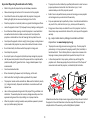
•
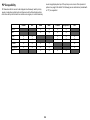
In the unlikely event of a lamp rupture, particles may exit through the
projector vents. Please keep people, food, and drinks out of the “keep out”
area under and around the projector, as indicated by the illustration.
Follow these instructions to help ensure image quality and lamp life over the life of
the projector. Failure to follow these instructions may affect the warranty. For
complete details of the warranty, see the Safety/Warranty Booklet.
3
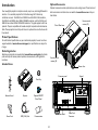
Introduction
Optional Accessories
Optional accessories include optional lenses and a ceiling mount. These items and
other accessories can be found on our website at www.infocus.com or at your
local dealer.
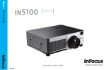
Your new digital projector is simple to connect, easy to use, and straightforward to
maintain. It is a versatile projector that is flexible enough to fit almost any
installation scenario. The IN5552L and IN5852L have XGA 1024 x 768 resolution,
the IN5554L and IN5854L have WXGA 1280x800 resolution, and the IN5555L and
IN5855L have native WUXGA 1920x1200 resolution. This guide applies to all three
products. They are compatible with a wide variety of computers and video devices.
Note: These projectors do not ship with a lens. An optional lens must be chosen for
the product.
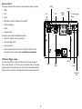
Remote control
receiver (IR)
Color Wheel cover
Product Specifications
To read the latest specifications on your multimedia projector, be sure to visit our
support website at www.infocus.com/support, as specifications are subject to
change.
Online Registration
Register your projector on our website at www.infocus.com/register to activate
your warranty and receive product updates, announcements, and registration
incentives.
Remote control
receiver (IR)
Included Items
ON
FOCUS
POWER
Lens
Elevator Foot
Connector panel
OFF
Keypad
Dust Cap
ZOOM
TEST
PATTERN
LENS SHIFT
ENTER
MENU
INPUT
AUTO SYNC
EXIT
PICTURE
ASPECT
NETWORK
PIP
1
2
3
OVERSCAN
FREEZE
LAMP MODE
4
5
6
INFO.
LIGHT
7
8
9
CLEAR
SHUTTER
ID SET
0
Remote Control
Projector
Optional RGBCMY
Color Wheel
Power Cord
RGB (VGA) Cord
Documentation
Power switch
4
Power Cord
Connector
Connector Panel
HDMI
The projector provides both computer and video connection options, including:
•
HDMI
•
DVI-D
•
3G-SDI
•
BNC RGBHV and YPbPr for RGBHV, EDTV and HDTV
•
RGB (VGA) computer
•
S-video
•
Composite video
SDI
DVI-D
RGBHV
YPbPr
Wired
remote
12V Screen Trigger
Output
The projector also provides the following connectors:
•
LAN port for network control and web server.
•
12V screen trigger output
•
Wired remote jack
•
RS-232 connector for serial control. Command control codes are in the
Appendix and on our support website at www.infocus.com/support.
12V Screen Trigger output
The 3.5mm mini-jack screen trigger provides a 12 volt, 0.25 amp DC output. It
turns on when the lamp is lit. If you connect your projection screen to this output
using the cable that came with your screen, the screen will move down when the
lamp is turned on and return to its storage position when the lamp is turned off.
LAN
RGB
(VGA)
RS-232
S-video
Composite
video
5
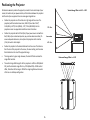
Positioning the Projector
To determine where to position the projector, consider the size and shape of your
screen, the location of your power outlets, and the distance between the projector
and the rest of your equipment. Here are some general guidelines:
•
•
Vertical Image Offset is -60-% ~ +20%
Position the projector on a flat surface at a right angle to the screen. The
projector (with the standard zoom lens, LENS-074) must be at 55.8”/
1.42m(XGA) ; 60.2”/1.53m (WXGA) ; 57.2”/1.45m (WUXGA) from the
projection screen. See appendix for additional lens information.
20% offset
Position the projector within 10 feet (3m) of your power source and within 6
feet (1.8m) of your video device (unless you purchase extension cables). To
ensure adequate cable access, do not place the projector within 6 inches
(.15m) of a wall or other object.
•
Position the projector to the desired distance from the screen. The distance
from the lens of the projector to the screen, the zoom setting, and the video
format determine the size of the projected image.
•
The image exits at a given angle. However, the lens shift feature makes the
image offset variable.
•
The vertical image offset range for all the projectors is -60% to +20% (default
0%), and the horizontal image offset is +/-10% (default 0%). At 20% vertical
offset, the bottom of the image is 20% of the image height above the center
of the lens in a tabletop configuration.
lens center
-60% offset
Horizontal Image Offset is +/-10%
6
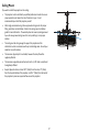
Ceiling Mount
If you wish to install the projector on the ceiling:
•
The projector must be installed by a qualified professional in order to ensure
proper operation and reduce the risk of hazards or injury. It is not
recommended you install the projector yourself.
•
We strongly recommend using InFocus approved ceiling mounts for proper
fitting, ventilation and installation. Refer to the ceiling mount installation
guide for more information. The warranty does not cover any damage caused
by use of non-approved ceiling mount kits or by installing in an improper
location.
•
The ceiling must be strong enough to support the projector and the
installation must be in accordance with any local building codes. Consult your
dealer for more information.
•
The maximum physical pitch is unlimited, however the lamp life will be
negatively affected.
•
The maximum supported physical horizontal roll is +/-10º. Note: Lamp life will
be negatively affected.
•
Keep all adjacent surfaces at least 19.7” (50cm) from the sides, 12” (30cm)
from the top and bottom of the projector, and 27.6” (70cm) from the back of
the projector to preserve required airflow around the projector.
10º
7
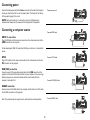
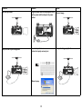
Connecting power
Connect the black power cord to the Power connector on the side of the projector
and to your electrical outlet. Turn on the power switch. The Power LED on the top
of the projector (page 12) turns red.
Connect power cord
NOTES: Note: Connection to a circuit with a minimum of 20A capacity is
recommended. Always use the power cord that shipped with the projector.
Connecting a computer source
Connect HDMI cable
HDMI 1.3 connection
Plug an HDMI cable into the video out connector on the video device and into the
HDMI connector on the projector.
MOLEX
MOLEX
To take advantage of HDMI 1.3 Deep Color (30 bit) you must have a 1.3-compatible
source.
DVI-D
Connect DVI-D cable
Plug a DVI-D cable into the video out connector on the video device and into the
DVI connector on the projector.
RGB (VGA) connection
Connect one end of the provided computer cable to the RGB connector on the
projector and the other to the VGA connector on your computer. If you are using a
desktop computer, you will need to disconnect the monitor cable from the
computer’s video port first.
Connect RGB (VGA) cable
RGBHV connection
Connect one end of the BNC cable to the computer and the other end of the cable
into the BNC connectors on the projector.
Connect RGBHV cable
Note: This projector does not support audio. Audio must be routed separately.
8
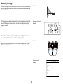
Displaying an image
Press Power button
Touch the Power button on the keypad or the remote.
The Power button blinks green and the fans start to run. When the lamp turns on,
the start up screen will display and the Power button will become solid green. It
can take a minute for the image to achieve full brightness.
No start up screen? Get help on page 13.
Turn on computer or
video device
Turn on your computer or video device.
The image should appear on the projection screen. If it doesn’t, press the Input
button on the projector’s keypad or remote.
If you are using a laptop, make sure its external video port is active.
Many laptops do not automatically turn on their external video port when a
projector is connected. Usually a key combination like Fn + F8 or CRT/LCD key turns
the external display on and off. Locate a function key labeled CRT/LCD or a function
key with a monitor symbol. Press Fn and the labeled function key simultaneously.
Activate laptop’s external port
Refer to your laptop’s documentation for more information about your laptop’s key
combination.
Monitor key or
LCD/CRT key
No laptop image? Try pressing the Auto Sync button on the keypad or
remote. Get help on page 22.
Fn key
9
Adjusting the image
Position the projector to the desired distance from the screen at a 90 degree angle
to the screen. See the Appendix for screen sizes and distances associated with the
various lens options.
Adjust distance
If the image is square but not centered on the screen or viewing area, adjust Zoom
or Lens Shift using the keypad or remote. Focus can also be adjusted using the
keypad or remote.
Adjust zoom, focus and
lens shift.
Rotate the elevator feet for adjustment of the projector’s height. Avoid placing
your hands near the hot exhaust vent at the back of the projector.
Adjust height
Adjust the Contrast or Brightness in the Picture menu. See page 25 for help with
these menu adjustments.
Elevator feet
Adjust contrast and
brightness.
10
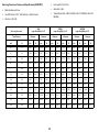
INPUT
PICTURE
Picture Mode
Contrast
Brightness
Adaptive Contrast
Saturation
Hue
Gamma
Color
Sharpness
Noise Reduction
Aspect Ratio
Overscan
VGA Setup
Auto Sync
LAMPS
<
<
<
<
<
<
<
<
<
<
<
<
ALIGNMENT
High Bright
100
100
Off
----------Video
Enter
0
0
16:10
Off
Enter
Execute
>
>
>
>
>
>
>
>
>
>
>
>
CONTROL
SERVICE
Connecting a video device
the component cable into the adapter and plug the adapter into the RGB
connector.
You can connect video devices such as VCRs, DVD players, camcorders, digital
cameras, video game consoles, HDTV receivers, and TV tuners to the projector.
Note: This projector does not support audio. You must connect audio directly from
your source to a stereo or home theater system.
Component offers the highest quality analog video output.
S-video connection
If your video device uses a round, four-prong S-video connector, plug an S-video
cable into the S-video connector on your video device and into the S-video
connector on the projector.
You can connect the projector to most video devices that can output video. You
cannot directly connect the coaxial cable that enters your house from a cable or
satellite company; the signal must pass through a tuner first. Examples of tuners
are digital cable boxes, VCRs, digital video recorders, and satellite TV boxes.
Basically, any device that can change channels is considered a tuner.
S-video delivers higher quality video output than composite.
Composite video connection
Plug the composite video cable’s yellow connector into the video out connector on
the video device. Plug the other yellow connector into the yellow Video
connector on the projector.
Although the aspect ratio is automatically selected by the projector based on the
signal input, you can change the aspect ratio, if desired. The projector’s Aspect
Ratio setting is accessed through the Aspect button on the remote or through the
projector’s Picture Menu. See page 25 for more information.
Composite Video output from composite connections is not as high quality as Svideo or as Component.
RGB (VGA) connection
Video device connections
If your video device has a 15-pin VGA output, plug one end of the included
computer cable into the VGA connector on your video source. Plug the computer
cable into the RGB connector on the projector.
No video cables are provided with the projector. You can order cables from InFocus
or use your own.
3G-SDI Out
HDMI 1.3 connection
Connect one end of a BNC coaxial cable into the SDI Out connector on the
projector and the other end into another projector to daisy-chain the projectors.
HDMI is a standard, uncompressed, all-digital audio/video interface. HDMI
provides an interface between sources, such as set-top boxes, DVD players, and
receivers and your projector. Plug an HDMI cable into the video out connector on
the video device and into the HDMI connector on the projector.
To take advantage of HDMI 1.3 Deep Color (30 bit) you must have a 1.3-compatible
source.
3G-SDI
Connect a BNC coaxial cable into the video device. Plug the other end of the cable
into the SDI In connector on the projector.
Component video connection
Plug a BNC type component cable into the video device. Plug the other end of the
component cable into the YPbPr connectors as appropriate.
In addition, a Component to VGA adapter can be used in conjunction with the VGA
connectors. Plug the component cable into the video device. Plug the other end of
11
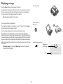
Shutting down the projector
Table 1: Status indicator LED behavior and meaning
Auto Power Off
The projector has an Auto Power Off feature that automatically turns the projector
off if no active sources are detected and no user interaction with the projector is
performed for 20 minutes. By default, this feature is off.
Turning off the projector
To turn the projector off, press the Power button on the remote or keypad twice.
The lamp turns off and the LED blinks orange for 10 seconds while the fans
continue to run to cool the lamp. When the lamp has cooled, the LED lights red and
the fans stop. Unplug the power cable and turn off the power switch to completely
power off the projector.
Troubleshooting your setup
The Status Indicator LEDs on top of the projector indicates the state of the
projector and is helpful when troubleshooting.
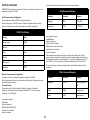
LED Indicator
Meaning
Power:
Solid red
The projector is plugged in.
Blinking green
The power button has been pressed and the software is
initializing.
Solid green
The projector is on and initialized.
Blinking orange
The power button has been pressed to turn the projector
off and the fans are running to cool the projector.
Status
Turn the projector off and wait one minute, then turn the
projector on again. If the Status LED turns on again, service
is required. Visit www.infocus.com/support to contact
service.
Lamp1/Lamp 2:
Flashing Green
The lamp is warming up.
Solid Green
The lamp is on.
Flashing Red
12
A lamp error occured. Turn the projector off and wait one
minute, then turn the projector on again. If the lamp light
turns on again, replace the lamp and reset the lamp timer
(page 35). Note: the projector may need to be serviced.
Solid Red
The lamp needs to be replaced.
Temp
The projector is too hot. Make sure the vents aren’t blocked
(see page 18). Turn the projector off and wait one minute,
then turn the projector on again. Contact Technical Support
if the problem persists. Visit www.infocus.com/support to
contact service.
Shutter
The shutter is closed. Press the Shutter button to open the
shutter.
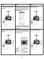
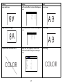
Problem
Solution
Result
No start up screen.
Plug the power cord into the projector, turn
on the power switch and press the power
button.
Correct image.
Only the start up screen appears.
Press the Input button to
activate the laptop’s external port.
Computer image projected.
B
B
Restart laptop
13
B
Problem
Solution
Result
No computer image, just the words “Signal
out of range.”
Press the Auto Sync button on the keypad or remote.
To adjust computer refresh rate, go to Control Panel >
Display > Settings > Advanced > Adapter (location
varies by operating system).
Computer image projected.
Signal out
of range
B
B
B
You may also need to set a different resolution on your
computer, as shown in the following problem, “image
fuzzy or cropped.”
Only my laptop’s background appears, not the
Desktop icons.
B
Windows - Disable “Extend my Windows Desktop” in
Control Panel > Display > Settings > Display 2 (location
varies by operating system).
Background and Desktop projected.
B
B
Uncheck this
option, then
click Apply
14
B
Problem
Solution
Result
Image fuzzy or cropped
Set your computer’s display resolution to the
native resolution of the projector (Start >
Settings > Control Panel > Display > Settings
tab).
Image clear and not cropped.
A
A
A
For a laptop,
disable laptop
monitor or
turn-on dualdisplay mode
Adjust Lens Shift using the keypad or remote.
Image not centered on screen.
B
Correct image.
B
B
15
B
Problem
Solution
Result
Image not square.
Adjust the angle of the projector, so that it is
square with the screen.
Square image.
Image not sharp.
Adjust Sharpness in the Picture menu.
Correct image.
INPUT
Image does not fit 4:3 or 16:9 screen.
PICTURE
LAMPS
ALIGNMENT
Picture Mode
Contrast
Brightness
Adaptive Contrast
<
<
<
<
High Bright
100
100
Off
>
>
>
>
Saturation
Hue
Gamma
Color
Sharpness
Noise Reduction
Aspect Ratio
Overscan
VGA Setup
Auto Sync
<
<
<
<
<
<
<
<
----------Video
Enter
0
0
16:10
Off
Enter
Execute
>
>
>
>
>
>
>
>
CONTROL
SERVICE
Change Aspect Ratio to 4:3 or 16:9 in the Picture
menu.
INPUT
PICTURE
Picture Mode
Contrast
Brightness
LAMPS
<
<
<
ALIGNMENT
High Bright
100
100
>
>
>
Adaptive Contrast
<
Off
>
Saturation
Hue
Gamma
Color
<
<
<
<
----------Video
Enter
>
>
>
>
Sharpness
<
0
>
Noise Reduction
Aspect Ratio
Overscan
VGA Setup
<
<
<
0
16:10
Off
Enter
>
>
>
Auto Sync
Execute
16
CONTROL
SERVICE
Correct image.
Problem
Solution
Result
Image upside down.
Turn Projection Mode to Front in the Alignment
menu.
Correct image.
A
Image reversed left to right.
INPUT
ALIGNMENT
CONTROL
SERVICE
Projection Mode
<
Front
>
Fan Mode
<
Normal
>
Enter
Enter
Center Lens
Execute
Warp
Blanking
Enter
Enter
Edge Blend
Enter
Turn Projection Mode to Front in the Alignment
menu.
INPUT
PICTURE
LAMPS
ALIGNMENT
Projection Mode
Fan Mode
Lens Control
Lens Memory
Center Lens
Warp
Blanking
Edge Blend
CONTROL
<
<
PICTURE
Picture Mode
Contrast
Brightness
Adaptive Contrast
Saturation
Hue
LAMPS
ALIGNMENT
<
<
<
<
<
<
High Bright
100
100
Off
-----------
Gamma
Color
<
<
Video
Enter
>
>
Sharpness
Noise Reduction
Aspect Ratio
Overscan
VGA Setup
Auto Sync
<
<
<
<
0
0
16:10
Off
Enter
Execute
>
>
>
>
17
>
>
>
>
>
>
Correct image.
SERVICE
Front
Normal
Enter
Enter
Execute
Enter
Enter
Enter
>
>
Adjust color, tint, brightness, contrast in the
Picture menu and/or color space in the Input
menu.
INPUT
COLOR
LAMPS
Lens Control
Lens Memory
A
Projected colors don’t match source.
PICTURE
CONTROL
Correct image.
SERVICE
COLOR
Problem
Solution
Result
The video embedded in my PowerPoint
presentation does not play on the screen.
Turn off the internal LCD display on your laptop.
Embedded video plays correctly.
B
B
B
B
Lamp won’t turn on and the Temp LED is on.
Make sure vents aren’t blocked, turn the
projector off and allow it to cool for one minute.
Temp LED
18
Lamp turns on.
B
Problem
Solution
Result
Lamps won’t turn on and the Lamp LEDs are
turned on.
The lamps must be replaced (see page 34).
Lamp Doors
Lamp LEDs
Replace
lamps
Still need assistance?
If you need assistance, visit our support website at www.infocus.com/support
or call us. Check out the How To section for additional information on using this
projector for home theater or gaming applications.
This product is backed by a limited warranty. An extended warranty plan may be
purchased from your dealer. When sending the projector in for repair, we
recommend shipping the unit in its original packing material, or having a
professional packaging company pack the unit. Please insure your shipment for its
full value.
19
Lamps turn on.
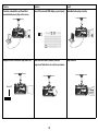
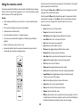
Using the remote control
To operate, point the remote at the projector (not at the computer). The range of
optimum operation is about 30’ (9m).
The remote uses two (2) AA batteries (not included). Install batteries by removing
the cover from the remote’s back, aligning the + and - ends of the batteries, sliding
them into place, and then replacing the cover.
Press the remote’s Power On and Off buttons to turn the projector on and off
(see page 12 for shutdown information).
Press the remote’s Menu button to open the projector’s menu system. Use the
arrow buttons to navigate, and the Enter button to select features and adjust
values in the menus. See page 23 for more information on the menus.
Caution:
•
When disposing of batteries, be sure to do so in an environmentally proper
manner.
•
If the remote control gets wet, wipe it dry immediately.
•
Focus button turns on the focus control.
•
Avoid excessive heat and humidity.
•
Zoom button turns on the zoom control.
•
Ensure the batteries’ polarity (+/-) is aligned correctly.
•
Test Pattern button toggles between different test patterns.
•
Do not mix new and old batteries together, or different types of batteries
together.
•
Lens Shift button turns on the lens shift control.
•
Replace the batteries as soon as they run out.
•
Exit closes the onscreen menus (page 23).
•
Remove the batteries from the remote control when storing or when the
remote will not be used for a prolonged period.
•
Input button to switch between sources.
•
Picture button toggles between different picture modes.
•
Network button displays network information.
•
Auto Sync button resynchronizes the projector to the source.
•
Aspect button toggles between aspect ratios (see page 25).
•
PiP button turns on the PiP feature.
•
Overscan button toggles between overscan modes.
•
Freeze button freezes/unfreezes the source image being displayed.
•
Lamp Mode button toggles between single and dual lamp mode.
•
- button is not used on this projector.
•
Info. button displays projector and source information.
•
Light button turns on the remote’s backlight.
•
Clear button clears the ID Set entry information.
•
Shutter button to blank the screen.
•
ID Set button allows the user to specify the remote and projector ID set. This
is helpful when more than one projector is used in a room. See the Setting an
ID Code for the Remote and Projector section on the next page.
ON
FOCUS
POWER
The remote also has:
OFF
ZOOM
TEST
PATTERN
LENS SHIFT
ENTER
MENU
EXIT
INPUT
PICTURE
NETWORK
AUTO SYNC
ASPECT
PIP
1
2
3
OVERSCAN
FREEZE
LAMP MODE
4
5
6
INFO.
LIGHT
7
8
9
CLEAR
SHUTTER
ID SET
0
20
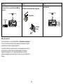
Wired Remote Option
If the wireless range of the remote is not sufficient, the remote can be wired
directly into the projector’s Wired Remote connector.
press the button which corresponds with the projector ID number set in Step
#1. For example, pressing ID Set and “3” on the remote will set the remote ID
code to “3”.
5 Continue holding these buttons until a confirmation message appears. For
Setting an ID Code for the Remote and Projector
example, if both the projector and remote ID codes are set to “3”successfully,
the message, “[PJ_ID] 03 ... [RC_ID] 03 ... [RC_TBL] 1” displays. Note: If the
PJ_ID and RC_ID numbers match, but the RC_TBL displays 0, press and hold the
ID Set button for an additional 5-8 seconds.
A unique ID number can be set, pairing both the projector and remote, so that the
remote will only control the projector it is paired with.
Note: Always press and hold the ID Set button before pressing any other buttons
on the remote and always release the ID Set button after releasing the other
buttons.
6 The projector and remote are now paired. Other remotes will not operate this
To review the current ID Code settings: Press and hold the ID Set button on the
remote for 5-8 seconds.
projector.
To clear the current ID Code settings: Press and hold the ID Set button and the
Clear button simultaneously for 5-8 seconds, or until the message “ID Cleared”
displays. This clears the remote ID number.
If the projector and remote ID codes have never been set, the following message
displays, “[PJ_ID] X ... [RC_ID] X ... [RC_TBL] 0”.
PJ_ID refers to the current projector ID number and RC_ID refers to the current
remote ID number.
Note: It is not necessary to clear the projector ID number, however if you wish to
do this, you must reset the projector ID number using the RSE command code
“RSE255”.
RC_TBL refers to the remote control table and displays 1 if the projector and
remote are paired or 0 if they are not paired.
To set the ID Code:
1 Using the “RSE” RS232 command (see “Control commands” on page 47 for
Troubleshooting the remote
more information), set the projector ID code. Valid commands are RSE1
through RSE9. For example, RSE3 sets the projector ID code to “3”.
2 To verify that the projector ID number has been set correctly, press and hold
the ID Set button on the remote for 5-8 seconds and verify that the projector
ID number ([PJ_ID]) displays the number you entered using the RSE command.
In our example, the following message would display, “[PJ_ID] 3 ... [RC_ID] X ...
[RC_TBL] 0”.
3 To set the remote ID number, press and hold the ID Set button and Menu
button simultaneously for 5-8 seconds or until the message, “Please press ID
SET + #”, displays.
4 While continuing to hold the ID Set button, release the Menu button and
21
•
Make sure the batteries are installed in the proper orientation and are not
dead.
•
Make sure you’re pointing the remote at the projector or the screen, not the
computer, and are within the remote range of 32.8’ (10m) at +/- 30 degrees.
For best results, point the remote at the projector.
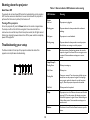
Using the keypad buttons
Most buttons are described in detail in other sections, but here is an overview of
their functions:
Power–turns the projector on and off (page 8).
Input–changes the active source (page 8).
Auto Sync–resynchronizes the projector to the source.
Aspect - toggles between different aspect ratio modes.
Menu navigation
buttons
Shutter Open - opens the shutter.
Shutter Close - closes the shutter.
Menu - opens the onscreen menus (page 23).
Up/Down/Left/Right arrows–navigates to and adjusts settings in the menus
(page 23).
Enter - confirms choices made in the menus (page 23).
Exit - closes the onscreen menus (page 23).
Lens Shift - shifts the lens position up, down, left and right.
Focus +/- - adjusts the focus of the image.
Zoom +/- - increases and decreases the image size.
22
Using the menus
INPUT
To open the menus, press the Menu button on the keypad or remote. Use the left
and right arrow buttons to move between the menus, and the up and down to
navigate to the desired menu item.
PICTURE
LAMPS
ALIGNMENT
CONTROL
SERVICE
INPUT
PICTURE
LAMPS
Input Selection
Enter
Picture Mode
<
PiP
Test Pattern
Enter
Enter
Contrast
Brightness
<
<
ALIGNMENT
High Bright
100
100
Color Space
<
Auto
>
Adaptive Contrast
<
Off
>
Input Lock
Background
<
<
Auto
Logo
>
>
Saturation
Hue
<
<
-----------
>
>
Video Standard
<
------
>
Gamma
<
Video
>
Auto Sync Adjust
<
Always
>
Color
Sharpness
<
<
Enter
0
>
>
Noise Reduction
<
0
>
Aspect Ratio
Overscan
<
<
16:10
Off
>
>
Once a menu item is highlighted, the left and right arrow buttons can be used to
adjust the value, select an option, turn the feature on or off, or enter a submenu.
VGA Setup
Auto Sync
Press the Exit button to exit the menu system immediately or press the Menu
button to go back to the main menu bar and ultimately close the menus.
CONTROL
SERVICE
>
>
>
Enter
Execute
Input menu
Picture Menu
The menus are grouped by usage:
•
The Input menu provides source specific selection and adjustments.
•
The Picture menu provides common image adjustments.
•
The Lamps menu provides lamp selection and power adjustments.
•
The Alignment menu provides installation specific adjustments.
•
The Control menu provides set-up type adjustments that are not changed
often.
•
The Service menu provides information about the projector and source.
INPUT
PICTURE
LAMPS
ALIGNMENT
CONTROL
Mode
Power
High Altitude
<
<
<
Custom Power Level
Lamp 1 Status
Lamp 2 Status
<
INPUT
SERVICE
High Bright
Eco
Off
Off
Off
On
PICTURE
LAMPS
ALIGNMENT
CONTROL
SERVICE
>
>
>
Projection Mode
<
Front
>
Fan Mode
Lens Control
<
Normal
Enter
>
>
Lens Memory
Center Lens
Warp
Enter
Execute
Enter
Blanking
Edge Blend
Lamps menu
INPUT
PICTURE
LAMPS
ALIGNMENT
Eco Network Power
Auto Power Off
Auto Power On
Projector Control
Network
Start Up Logo
Trigger
Auto Search
Dynamic Black
Language
Menu navigation
buttons
Control menu
23
Enter
Enter
Alignment menu
CONTROL
<
<
<
<
<
<
<
<
SERVICE
Standard
Off
Off
Network
Enter
On
Auto
Off
Off
Enter
INPUT
>
>
>
>
>
>
>
>
PICTURE
LAMPS
Model :
Serial Number :
Software Version :
Active/PiP Source :
Pixel Clock :
Signal Format :
H/V Refresh Rate :
Lamp 1 Time :
Lamp 2 Time :
Power On Time :
Blue Only
Factory Reset
ALIGNMENT
CONTROL
SERVICE
IN5552L
C277XXXX00807
ME01-GE02-Ub02-5050-39-DPNE02-P03-E07
VGA
/ Off
83.51 MHZ
1280x800@60Hz
H: 49.726 KHZ V: 60 HZ
5 HRS
3 HRS
5 HRS
<
Off
>
Enter
Service menu
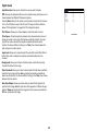
Input menu
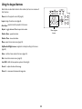
Input Selection: Allows you to choose the source you wish to display.
INPUT
PiP: Allows you to display two distinct sources simultaneously, switch sources, and
choose between five different PiP placement options.
Press the Enter button on the remote or control panel to access the PiP submenu.
Turn on the PiP Option to access the PiP Input, PiP Swap and Position features.
Review “PiP Compatibility” on page 46 for PiP configuration options.
Test Pattern: Allows you to choose between various test pattern screens.
PICTURE
LAMPS
Input Selection
Enter
PiP
Test Pattern
Enter
Enter
ALIGNMENT
Color Space
<
Auto
>
Input Lock
Background
<
<
Auto
Logo
>
>
Video Standard
<
------
>
Auto Sync Adjust
<
Always
>
Input menu
Color Space: This option applies to computer and component video sources. It
allows you to select a color space that has been specifically tuned for the input
signal. When Auto is selected, the projector automatically determines the
standard. To choose a different setting, turn off Auto, then choose between the
other computer and video options.
Input Lock: Allows you to manually select the output frame rate (48Hz, 50Hz or
60Hz). When Auto is selected, the projector automatically determines the
standard.
Background: Allows you to select a blank blue, black or white startup screen
instead of the default InFocus logo.
Video Standard: Allows you to select a video standard that has been specifically
tuned for the input signal. When Auto is selected, the projector automatically
determines the standard. To choose a different setting, turn off Auto, then choose
between the other options.
Auto Sync Adjust: Allows you choose when you would like the projector to
synchronize the image. Auto will synchronize the image when a different timing is
detected. Always will synchronize the image each time a new source is detected.
Off never synchronizes the image.
24
CONTROL
SERVICE
Picture menu
Picture Mode: Presets are provided that optimize the projector for displaying
computer presentations and video images under certain conditions. Select
between High Bright, Presentation and Video.
INPUT
Contrast: Controls the degree of difference between the lightest and darkest
parts of the picture and changes the amount of black and white in the image.
Brightness: Changes the intensity of the image.
Hue: Composite/S-video sources only. Allows you to adjust the color hue.
Gamma: Allows you to choose Video, Film, and Graphics color gamma options.
Color: Press the Enter button on the remote or control panel to access the color
submenu.
Color Temperature: Changes the intensity of the colors. Select a listed relative
warmth value. (Composite/S-video sources only.)
•
Trim: Allows you to change the color lift (offset) and color gain of the red,
green and blue channels.
<
<
<
ALIGNMENT
High Bright
100
100
Off
>
>
>
Adaptive Contrast
<
Saturation
Hue
<
<
-----------
>
>
Gamma
<
Video
>
>
Color
Sharpness
<
<
Enter
0
>
>
Noise Reduction
<
0
>
Aspect Ratio
Overscan
<
<
16:10
Off
>
>
Enter
Execute
Picture menu
Saturation: Composite/S-video sources only. Allows you to adjust the color
saturation levels of the image.
•
LAMPS
Contrast
Brightness
VGA Setup
Auto Sync
Adaptive Contrast: Turn on this feature to allow the projector to modify the
contrast ratio based on the different areas of the image.
PICTURE
Picture Mode
Sharpness: Changes the clarity of the edges of a video image. Select a sharpness
setting.
Noise Reduction: Reduces temporal and/or spatial noise in the image.
Aspect Ratio: Adjusts ratio of the image width to image height. Choose between
16:9, 1.88, 2.35, Letterbox, Native, Unscaled, 5:4, 4:3, and 16:10.
Overscan: Removes noise around the video image.
VGA Setup: Press the Enter button on the remote or control panel to access the
VGA Setup submenu. You can adjust H total, H Start, H Phase, and V Start.
Auto Sync: Forces the projector to reacquire and lock to the input signal. This is
useful when signal quality is marginal. Press the Enter button on the remote or
control panel to automatically synchornize the signal.
25
CONTROL
SERVICE
Lamps menu
Mode: Allows you to choose between single and dual lamp modes. Note: When
using single lamp mode, the lamp with the least number of lamp hours turns on.
Individual lamps are not user selectable.
INPUT
PICTURE
LAMPS
ALIGNMENT
CONTROL
<
Power
High Altitude
<
<
Eco
Off
>
>
Custom Power Level
<
Off
>
Lamp 1 Status
Lamp 2 Status
Power: Allows you to choose between Normal, Custom Power Level, and Eco
power levels. When Custom Power Level is chosen, the Custom Power Level menu
item becomes adjustable. When Eco is chosen, the lamp output and the fan speed
are lowered, making the lamp dimmer and the projector quieter.
High Altitude: This feature should be turned On when the projector is being
used in an environment at 5500’ (1600m) and above sea level. Note: Turning High
Altitude On will cause the fan to run faster and slightly louder. If the projector is
used above 5500’ (1600’) and this feature is Off, the projector may shut down and
overheat.
Lamps menu
Custom Power Level: Allows you to adjust the power level you want manually
anywhere between the Eco power (minimum) and Normal power (maximum)
modes. Use the left and right arrow buttons to adjust the level. Press the Menu
button to return to the menu system or Exit to exit the Custom Power Level
feature and the menu system. Note: Power must be set to Custom Power Level to
access this feature.
Lamp 1 Status: Displays the status of Lamp 1. This is a read-only item. To select
single and dual lamp modes, use Mode.
Lamp 2 Status: Displays the status of Lamp 2. This is a read-only item. To select
single and dual lamp modes, use Mode.
26
SERVICE
Mode
High Bright
Off
On
>
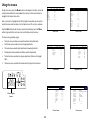
Alignment menu
Projection Mode: Allows you to change the orientation of the image for ceiling
mounted, rear-projection and table-top orientations.
INPUT
PICTURE
LAMPS
ALIGNMENT
CONTROL
Projection Mode
Fan Mode
Fan Mode: Allows you to manually select the fan tilt position. By default, the
position is horizontal (Normal), but if the projector is installed at an angle, it is
recommended that the fan mode be changed to Up or Down accordingly. Note:
Lamp life will be affected when Up or Down is selected. The fan speed also changes
with each orientation.
Lens Control
Lens Memory
Center Lens
Lens Control: Allows you to adjust the lens shift. This is the same as pressing the
Lens Shift button on the keypad or remote.
Center Lens: Press the Enter button on the remote or control panel to center
the lens.
Warp: Allows you to adjust keystone, rotation, pincushion/barrel, and corner
positions. This is especially useful when projecting on uneven or rounded surfaces
and when stacking two projectors and overlaying the images.
Press the Enter button to access the submenu. To make warp adjustments,
highlight the desired option and press the Enter button. Use the arrow keys to
make adjustments. Select Reset to return to factory default settings.
Blanking: Allows you to adjust the display range (blanking) at the top, bottom, left
and right edges of the input signal.
Edge Blend: When set to On, you can adjust the blend width and black level
uplift. Align Patterns are also available.
27
SERVICE
Front
Normal
Enter
Enter
Execute
Warp
Enter
Blanking
Edge Blend
Enter
Enter
Alignment menu
Lens Memory: Allows you to save the lens shift, zoom and focus settings for a
particular source into one of ten memory locations. Press the Enter button to
access the Lens Memory submenu. Use the Save Memory feature to save up to 10
source-specific lens settings. Use Load Memory to restore a saved setting.
<
<
>
>
Control menu
Eco Network Power: When this feature is set to Standard, Projector Control is
set to RS232 and all network functions continue to work when the projector is in
standby (powered off but connected to AC Power). When this feature is set to Eco,
network functions will not work when the projector is in standby.
INPUT
PICTURE
LAMPS
ALIGNMENT
Auto Power On
<
Off
>
Projector Control
Network
<
Network
Enter
>
Projector Control: Allows you to choose between RS232 and LAN projector
control methods.
Network: Press Enter button to review the current network settings. Note:
Network configuration and operation are made via the LAN Configuration Utility.
Start Up Logo: When this feature is on, the projector will display the InFocus
logo upon start-up.
Trigger: If you enable this feature and connect your projection screen to this
output using the cable that came with your screen, the screen will move down
when the lamp is turned on and the screen will return to its storage position, when
the lamp is turned off.
Auto Search: When this feature is on, the projector automatically finds the
active source. To display another source, you must manually select one by pressing
the Input button on the remote or keypad.
Dynamic Black: Turn this feature on when watching motion video in order to
improve the contrast of darker scenes.
Language: Allows you to select a language for the onscreen menu.
28
>
>
On
>
<
Auto
>
Auto Search
Dynamic Black
<
<
Off
Off
>
>
Control menu
<
Standard
Off
Trigger
Language
Auto Power On: When this feature is on, the projector automatically turns on
when electrical power is connected. This allows control of ceiling mounted
projectors with a wall power switch.
SERVICE
<
<
Start Up Logo
Auto Power Off: When this feature is on, the projector is automatically turned
off after no signals are detected for 20 minutes. If an active signal is received
before the projector powers down, the image will be displayed.
CONTROL
Eco Network Power
Auto Power Off
Enter
Service menu
Model: Displays the model number of the projector (read-only).
INPUT
Serial Number: Displays the serial number of the projector (read-only).
Software Version: Displays the current firmware version the projector is using
(read-only).
Active/PiP Source: Displays the source type which is being used in the Picturein-Picture window (read-only).
PICTURE
LAMPS
ALIGNMENT
Software Version :
ME01-GE02-Ub02-5050-39-DPNE02-P03-E07
Active/PiP Source :
Pixel Clock :
VGA
83.51 MHZ
Signal Format :
1280x800@60Hz
H/V Refresh Rate :
Lamp 1 Time :
H: 49.726 KHZ V: 60 HZ
5 HRS
Lamp 2 Time :
3 HRS
Power On Time :
Blue Only
5 HRS
<
Off
Enter
Pixel Clock: Displays the pixel clock settings of the current source (read-only).
Service menu
H/V Refresh Rate: Displays the horizontal and vertical refresh rate settings of the
current source (read-only).
Lamp 1 Time: Displays the number of hours Lamp 1 has been used (read-only).
Lamp 2 Time: Displays the number of hours Lamp 2 has been used (read-only).
Power On Time: Displays the number of hours the projector has been used
(read-only).
Blue Only: Displays a blue screen used for color calibration.
Factory Reset: Restores all settings to their defaults. Note: You must confirm this
before the reset will occur by click “OK” to the Reset Everything? dialog box.
29
SERVICE
IN5552L
C277XXXX00807
Factory Reset
Signal Format: Displays the signal format settings of the current source (readonly).
CONTROL
Model :
Serial Number :
/ Off
>
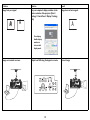
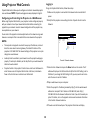
Using Projector Web Controls
Logging in
To log into Projector Web Controls, follow these steps:
Projector Web Controls allow you to configure and control a networked projector
via a web browser. NOTE: Projector web pages are always displayed in English.
1 Make sure the projector is connected to the network and connected to AC
power.
Configuring and Controlling the Projector via a Web Browser
2 Verify that the projector menu settings Control > Projector Control is set to
Before using Projector Web Controls, your projector must be configured properly
with your network. Consult your network administrator before connecting the
projector to your network. Incorrect network configuration of the projector may
cause problems on your network.
Network.
You can control the projector and make adjustments via the network using a web
browser on a computer that is connected to the same network as the projector.
INPUT
NOTES:
•
The computer and projector must each have proper IP addresses, and must
share the same subnet mask and gateway. The default IP address of the
projector is 192.168.0.100. The network settings of the projector can only be
changed via a web browser.
•
JavaScript must be enabled in your browser to use the projector web pages
properly. If JavaScript is disabled, see the Help files for your web browser for
details on how to enable it.
•
Projector Control in the projector’s Control menu must be set to Network. In
order to have access to Projector Web Controls at all times, Eco Network
Power in the Control menu must also be set to Standard.
PICTURE
LAMPS
ALIGNMENT
Network
CONTROL
SERVICE
IP Address
172.20.10.11
Eco Network Power
Auto Power Off
<
<
Subnet Mask
Gateway
255.255.255.00
172.20.10.01
Auto Power On
<
Off
>
<
<
Network
Enter
>
DHCP
Projector Control
Network
On
>
Standard
Off
>
>
Start Up Logo
<
On
>
Trigger
Auto Search
<
<
Auto
Off
>
>
Dynamic Black
<
Off
>
Language
Enter
Control > Network submenu
3 Go to Control > Network and press the Enter button on the remote. The IP
address will display on the left-hand side. Verify that the DHCP setting is set to
ON. Note: If you change the DHCP setting to ON, you may need to exit and reenter the menu to see the IP address.
4 Open a web browser on your computer.
5 Enter the projector's IP address (preceded by http://) into the web browser's
address bar. Example: If the IP address is 192.168.0.100, enter http://
192.168.0.100 into the browser's address bar. Note: If you don’t know the projector’s IP address, turn on the projector and review the network information
in the Control > Network submenu.
6 The web user interface will open. The projector information will display.
30
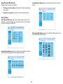
Using Projector Web Controls
Lens Adjustments Submenu: allows you to adjust the lens zoom, focus and
position.
Changes you make are applied immediately.
•
To change a numeric setting (e.g. Brightness): Click the corresponding up
or down button.
•
To perform a command (e.g. Source): Click the corresponding button.
Controls Menu
Source/General Submenu: allows you to change the video source, turn the
projector on or put it into standby, open and close the shutter, and set the projector control to network or RS232 control.
Geometry Adjust Submenu: allows you to adjust the blanking, warp, four corners and aspect ratio of the projector.
Image Settings Submenu: allows you to adjust contrast, brightness, saturation,
hue, sharpness, phase and gamma for the projected video source.
31
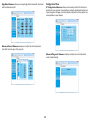
Configuration Menu
Edge Blend Submenu: allows you to adjust edge blend, blend width, black level
uplift and black level uplift.
IP Configuration Submenu: allows you to manually enter the IP address configuration for your projector. Consult with your network administrator before making any changes on this page; incorrect network configuration of the projector may
cause problems on your network.
Advanced Control Submenu: allows you to adjust the color temperature,
color offset and color gain of the projector.
Advanced Diagnostic Submenu: displays read-only error code information
used in troubleshooting.
32
Information Submenu: displays a read-only page of projector information.
To upgrade Projector Network Firmware: Upgrades the firmware for the
projector's network features (this firmware is separate from the regular projector
firmware). Key in the IP address followed by “/firmwareUpdate.htm” on the URL
box to activate the firmware update procedure. Follow the prompts to accomplish
the upgrade.
Note: DHCP must be disabled or OFF in order for the "/firmwareUpdate.htm" feature to work.
Troubleshooting Network Functions
•
•
•
33
If the network status displays “Not Connected” in the projector's Network
menu, or if the projector does not display its IP address, check the cable and
the network configuration.
If your web browser displays “Page Not Found” or a similar error when you try
to access the projector's web pages, verify that the projector is connected to
the network. Note: Projector Control in the Control menu must be set to
Network.
Make sure Eco Network Power in the Control menu is set to Standard (if it is
set to Eco, the projector web pages will not be available).
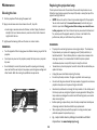
Maintenance
Replacing the projection lamp
Cleaning the lens
The lamp hours timer counts the number of hours each lamp has been in use.
When the lamp time has expired, the Lamp LED (Lamp1 or Lamp2) on top of the
projector will light solid red.
1 Turn the projector off and unplug the power cord.
•
2 Apply a non-abrasive camera lens cleaner to a soft, dry cloth.
• Avoid using an excessive amount of cleaner, and don’t apply the cleaner
directly to the lens. Abrasive cleaners, solvents or other harsh chemicals
might scratch the lens.
NOTE: Be sure to use the InFocus lamp module designed for this projector.
You can order new lamps from www.infocus.com (in select areas), your
retailer or your dealer. Only genuine InFocus lamps are tested for use
in this projector. Use of non InFocus lamps may cause electrical shock and
fire, and may void the projector warranty. InFocus is not liable for the
performance, safety or certification of any other lamps.
3 Lightly wipe the cleaning cloth over the lens in a circular motion.
WARNINGS:
WARNINGS:
•
Turn the projector off and unplug power cord before cleaning any part of the
projector.
•
Do not open any cover on the projector, except the lamp cover or projector
top cover.
•
Do not attempt to service this product yourself as opening and removing
covers will void the warranty and may expose you to dangerous voltage and
other hazards. Refer all servicing to qualified service personnel.
•
•
•
•
•
•
•
•
•
34
The projector uses two high-pressure mercury glass lamps. The lamps may
fail prematurely or rupture with a popping sound if jolted, scratched, or
handled while hot. The risk of lamp failure or rupture also increases as the
lamp age increases; it is recommended that both lamps be replaced
simultaneously when a Lamp LED (Lamp1 or Lamp2) is solid red.
To avoid burns, allow the projector to cool for at least 60 minutes before you
replace the lamps.
Unplug the power cord before replacing the lamps.
Do not drop the lamp modules. The glass may shatter and cause injury.
Do not touch the glass surface of the lamp modules. Fingerprints can obscure
projection sharpness and may cause the glass to shatter.
Be extremely careful when removing the lamp modules. In the unlikely event
that a lamp ruptures, small glass fragments may be generated. Although the
lamp modules are designed to contain most of these fragments, use caution
when removing them.
Before replacing a ruptured lamp, clean the lamp compartment and dispose
of cleaning materials. Wash hands after lamp replacement.
When replacing the lamps while the projector is ceiling-mounted, wear
protective eyewear to prevent eye injury.
Hg – Lamp contains mercury. Manage in accordance with local
disposal laws. See www.lamprecycle.org.
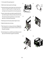
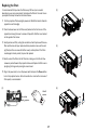
1 Turn the projector off and unplug the power cord.
(2)
(1)
2 Wait 60 minutes to allow the projector to cool thoroughly.
Wait 60
minutes
3 Remove the lamp doors by loosening 2 captive screws on each lamp door and
pulling the doors straight off being careful not to damage the ground wires
connecting the doors to the projector. Note: Do not remove the ground wires.
Turn off and unplug projector
4 Loosen the 3 captive shoulder screws (marked by arrows) that attach the first
lamp module to the projector. Carefully remove the lamp module. Do the same
for the second lamp module. Dispose of the lamps in an environmentally
proper manner in accordance with local disposal laws.
(3)
(4)
5 Carefully align and insert the new lamp modules and tighten the screws.
6 Replace the lamp doors and secure the screws.
7 Plug in the power cord, turn on the power switch and press the Power button
to turn the projector back on. Note: Connection to a circuit with a minimum of
20A capacity is recommended.
Lamp 1
8 To reset the lamp hour timer, use the RS232 commands, LMR (Lamp 1) and LDR
Lamp 2
(Lamp 2). See “Control commands” on page 47 for more information.
(6)
(5)
35
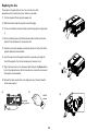
Replacing the lens
This projector is shipped without a lens. You can order a lens from
www.infocus.com (in select areas), your retailer or your dealer.
1 Turn the projector off and unplug the power cord.
(3)
2 Wait 60 minutes to allow the projector to cool thoroughly.
3 If a lens is not attached, remove the dust cap from the projector and go to Step
§
6.
4 If a lens is attached, press and hold the release button located near the lens
(marked “Press: Release lens”) to release the lock.
5 Twist the lens counter-clockwise and carefully remove it from the front of the
projector. Release the release button.
6 Insert the new lens into the projector carefully, arrow side up, through the
front of the projector. Turn the lens clockwise until you hear a click.
(4)
7 Plug in the power cord, turn on the power switch and press the Power button
to turn the projector back on. Note: Connection to a circuit with a minimum of
20A capacity is recommended.
(5)
8 Activate the Center Lens feature in the Alignment menu. (This will allow the
lens to work properly.)
(1)
(2)
Turn off and
unplug projector
(6)
Wait 60
minutes
36
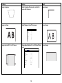
Replacing the filters
It is recommended that you clean the filters every 250 hours (or as needed
depending on your room environment) and replace the filters at the same time as
you replace the lamps. Follow the instructions below.
(2)
A
1 Turn the projector off and unplug the power cord. Wait 60 minutes to allow the
projector to cool thoroughly.
2 Press the release levers on the filter cover (located on the front corner of the
projector) and swing the cover to remove it. Repeat for the filter cover located
on the opposite front corner.
3 Gently pull out each filter, noting the orientation of each. Replace with the new
(3)
4 Gently re-insert the filters into the filter slots, making sure that the Air Flow
arrows are pointed towards the projector intake vents. Replace the filter covers
by aligning the hinges and pressing the covers closed.
5 Plug in the power cord, turn on the power switch and press the Power button
to turn the projector back on. Note: Connection to a circuit with a minimum of
20A capacity is recommended.
A
filters which come with your replacement lamp modules or vacuum the existing filters (and the area around the filter covers) carefully. Note: If the filters
are damaged or heavily soiled, they must be replaced.
(4)
(1)
Turn off and
unplug projector
Wait 60
minutes
37
AA
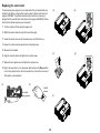
Replacing the color wheel
The color wheel of your projector is user replaceable. The color wheel which was
installed by the factory is designed for maximum color brightness and has 6 color
segments (RYGCWB). The optional color wheel which came as an accessory is
designed for fully saturated color and contains 6 color segments (RGBCMY). Follow
the instructions below to replace your color wheel.
(3)
(4)
(5)
(6)
1 Turn the projector off and unplug the power cord.
2 Wait 60 minutes to allow the projector to cool thoroughly.
3 Loosen the captive screw on the color wheel cover and lift the door up.
4 Loosen the 4 color wheel screws which are marked by arrows.
5 Remove the color wheel.
6 Align the new color wheel and tighten the 4 captive screws.
7 Replace the color wheel cover and tighten the captive screw.
8 Plug in the power cord, turn on the power switch and press the Power button
to turn the projector back on. Note: Connection to a circuit with a minimum of
20A capacity is recommended.
(1)
(2)
Turn off and
unplug projector
Wait 60
minutes
(7)
38
©
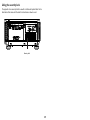
Using the security lock
The projector has a security lock for use with a Cable Lock System. Refer to the
information that came with the lock for instructions on how to use it.
Security lock
39
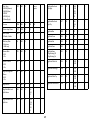
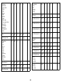
Appendix
•
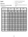
Lens Shift Position: -20% ~ +60% Vertical; +/-10% Horizontal
•
F-Number: 1.7 - 1.9; Focal Length: 26 - 34mm
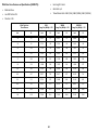
Optional Lenses
•
Zoom Ratio: 1.3:1
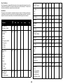
Standard Zoom Lens Features and Specifications (LENS-074):
•
Throw Distance Ratio: 1.43-1.88:1 (XGA); 1.53-2.02:1 (WXGA); 1.46-1.92:1
(WUXGA).
•
Motorized Zoom and Focus
XGA
Image Size (Width) +/-10%
Standard Zoom Lens
Throw Distance
Minimum
WXGA
Image Size (Width) +/-10%
Maximum
Minimum
WUXGA
Image Size (Width) +/-10%
Maximum
Minimum
Maximum
Inch
M
Inch
M
Inch
M
Inch
M
Inch
M
Inch
M
Inch
M
30
.76
15.96
0.41
20.98
0.53
14.85
0.38
19.61
0.50
15.63
0.40
20.55
0.52
36
.91
19.15
0.49
25.17
0.64
17.82
0.45
23.53
0.60
18.75
0.48
24.66
0.63
45
1.14
23.94
0.61
31.47
0.80
22.28
0.57
29.41
0.75
23.44
0.60
30.82
0.78
60
1.52
31.91
0.81
41.96
1.07
29.70
0.75
39.22
1.00
31.25
0.79
41.10
1.04
77
1.96
40.96
1.04
53.85
1.37
38.12
0.97
50.33
1.28
40.10
1.02
52.74
1.34
90
2.29
47.87
1.22
62.94
1.60
44.55
1.13
58.82
1.49
46.88
1.19
61.64
1.57
136
3.45
72.34
1.84
95.10
2.42
67.33
1.71
88.89
2.26
70.83
1.80
93.15
2.37
180
4.57
95.74
2.43
125.87
3.20
89.11
2.26
117.65
2.99
93.75
2.38
123.29
3.13
225
5.72
119.68
3.04
157.34
4.00
111.39
2.83
147.06
3.74
117.19
2.98
154.11
3.91
300
7.62
159.57
4.05
209.79
5.33
148.51
3.77
196.08
4.98
156.25
3.97
205.48
5.22
375
9.53
199.47
5.07
262.24
6.66
185.64
4.72
245.10
6.23
195.31
4.96
256.85
6.52
500
12.70
265.96
6.76
349.65
8.88
247.52
6.29
326.80
8.30
260.42
6.61
342.47
8.70
40
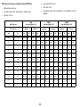
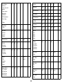
Wide Fixed Lens Features and Specifications (LENS-075):
•
Focal Length: 11.6mm
•
Motorized Focus
•
Zoom Ratio: n/a
•
Lens Shift Position: 0%
•
Throw Distance Ratio: 0.63:1 (XGA); 0.68:1 (WXGA); 0.64:1 (WUXGA)
•
F-Number: 1.85
Wide Fixed Lens
Throw Distance
XGA
Image Size (Width) +/-10%
WXGA
Image Size (Width) +/-10%
WUXGA
Image Size (Width) +/-10%
Inch
M
Inch
M
Inch
M
Inch
M
30
.76
47.62
1.21
44.12
1.12
46.88
1.19
36
.91
57.14
1.45
52.94
1.34
56.25
1.43
45
1.14
71.43
1.81
66.18
1.68
70.31
1.79
60
1.52
95.24
2.42
88.24
2.24
93.75
2.38
77
1.96
122.22
3.10
113.24
2.88
120.31
3.06
90
2.29
142.86
3.63
132.35
3.36
140.63
3.57
136
3.45
215.87
5.48
200.00
5.08
212.50
5.40
180
4.57
285.71
7.26
264.71
6.72
281.25
7.14
225
5.72
357.14
9.07
330.88
8.40
351.56
8.93
300
7.62
476.19
12.10
441.18
11.21
468.75
11.91
375
9.53
595.24
15.12
551.47
14.01
585.94
14.88
500
12.70
793.65
20.16
735.29
18.68
781.25
19.84
41
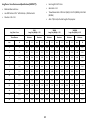
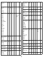
Wide Zoom Lens Features and Specifications (LENS-076):
•
Focal Length: 18.7-26.5mm
•
Motorized Zoom and Focus
•
Zoom Ratio: 1.41:1
•
Lens Shift Position: -20% ~ +60% Vertical; +/-10% Horizontal
•
•
F-Number: 1.85-2.5
Throw Distance Ratio: 1.04-1.48:1 (XGA); 1.11-1.59:1 (WXGA); 1.06-1.72:1
(WUXGA)
XGA
Image Size (Width) +/-10%
Wide Zoom Lens
Throw Distance
Minimum
WXGA
Image Size (Width) +/-10%
Maximum
Minimum
WUXGA
Image Size (Width) +/-10%
Maximum
Minimum
Maximum
Inch
M
Inch
M
Inch
M
Inch
M
Inch
M
Inch
M
Inch
M
30
.76
20.27
0.51
28.85
0.73
18.87
0.48
27.03
0.69
19.74
0.50
28.30
0.72
36
.91
24.32
0.62
34.62
0.88
22.64
0.58
32.43
0.82
23.68
0.60
33.96
0.86
45
1.14
30.41
0.77
43.27
1.10
28.30
0.72
40.54
1.03
29.61
0.75
42.45
1.08
60
1.52
40.54
1.03
57.69
1.47
37.74
0.96
54.05
1.37
39.47
1.00
56.60
1.44
77
1.96
52.03
1.32
74.04
1.88
48.43
1.23
69.37
1.76
50.66
1.29
72.64
1.85
90
2.29
60.81
1.54
86.54
2.20
56.60
1.44
81.08
2.06
59.21
1.50
84.91
2.16
136
3.45
91.89
2.33
130.77
3.32
85.53
2.17
122.52
3.11
89.47
2.27
128.30
3.26
180
4.57
121.62
3.09
173.08
4.40
113.21
2.88
162.16
4.12
118.42
3.01
169.81
4.31
225
5.72
152.03
3.86
216.35
5.50
141.51
3.59
202.70
5.15
148.03
3.76
212.26
5.39
300
7.62
202.70
5.15
288.46
7.33
188.68
4.79
270.27
6.86
197.37
5.01
283.02
7.19
375
9.53
253.38
6.44
360.58
9.16
235.85
5.99
337.84
8.58
246.71
6.27
353.77
8.99
500
12.70
337.84
8.58
480.77
12.21
314.47
7.99
450.45
11.44
328.95
8.36
471.70
11.98
42
Long Zoom 1 Lens Features and Specifications (LENS-077):
•
Focal Length: 52.8-79.1mm
•
Motorized Zoom and Focus
•
Zoom Ratio: 1.5:1
•
Lens Shift Position: -20% ~ +60% Vertical; +/-10% Horizontal
•
•
F-Number: 1.85 - 2.41
Throw Distance Ratio: 2.97-4.46:1 (XGA); 3.19-4.78:1 (WXGA); 3.04-4.56:1
(WUXGA)
•
Adds .3” (8.4mm) to the total length of the projector.
XGA
Image Size (Width) +/-10%
Long Zoom 1 Lens
Throw Distance
Minimum
WXGA
Image Size (Width) +/-10%
Maximum
Minimum
WUXGA
Image Size (Width) +/-10%
Maximum
Minimum
Maximum
Inch
M
Inch
M
Inch
M
Inch
M
Inch
M
Inch
M
Inch
M
30
.76
6.73
0.17
10.10
0.26
6.28
0.16
9.40
0.24
6.58
0.17
9.87
0.25
36
.91
8.07
0.21
12.12
0.31
7.53
0.19
11.29
0.29
7.89
0.20
11.84
0.30
45
1.14
10.09
0.26
15.15
0.38
9.41
0.24
14.11
0.36
9.87
0.25
14.80
0.38
60
1.52
13.45
0.34
20.20
0.51
12.55
0.32
18.81
0.48
13.16
0.33
19.74
0.50
77
1.96
17.26
0.44
25.93
0.66
16.11
0.41
24.14
0.61
16.89
0.43
25.33
0.64
90
2.29
20.18
0.51
30.30
0.77
18.83
0.48
28.21
0.72
19.74
0.50
29.61
0.75
136
3.45
30.49
0.77
45.79
1.16
28.45
0.72
42.63
1.08
29.82
0.76
44.74
1.14
180
4.57
40.36
1.03
60.61
1.54
37.66
0.96
56.43
1.43
39.47
1.00
59.21
1.50
225
5.72
50.45
1.28
75.76
1.92
47.07
1.20
70.53
1.79
49.34
1.25
74.01
1.88
300
7.62
67.26
1.71
101.01
2.57
62.76
1.59
94.04
2.39
65.79
1.67
98.68
2.51
375
9.53
84.08
2.14
126.26
3.21
78.45
1.99
117.55
2.99
82.24
2.09
123.36
3.13
500
12.70
112.11
2.85
168.35
4.28
104.60
2.66
156.74
3.98
109.65
2.79
164.47
4.18
43
Long Zoom 2 Lens Features and Specifications (LENS-078):
•
Focal Length: 78.5-121.9mm
•
Motorized Zoom and Focus
•
Zoom Ratio: 1.55:1
•
Lens Shift Position: -20% ~ +60% Vertical; +/-10% Horizontal
•
•
F-Number: 1.85 - 2.48
Throw Distance Ratio: 4.4-6.85:1 (XGA); 4.71-7.26:1 (WXGA); 4.50-7.00:1
(WUXGA)
•
Adds 1.93” (48.9mm) to the total length of the projector.
XGA
Image Size (Width) +/-10%
Long Zoom 2 Lens
Throw Distance
Minimum
WXGA
Image Size (Width) +/-10%
Maximum
Minimum
WUXGA
Image Size (Width) +/-10%
Maximum
Minimum
Maximum
Inch
M
Inch
M
Inch
M
Inch
M
Inch
M
Inch
M
Inch
M
30
.76
4.38
0.11
6.82
0.17
4.13
0.10
6.37
0.16
4.29
0.11
6.67
0.17
36
.91
5.26
0.13
8.18
0.21
4.96
0.13
7.64
0.19
5.14
0.13
8.00
0.20
45
1.14
6.57
0.17
10.23
0.26
6.20
0.16
9.55
0.24
6.43
0.16
10.00
0.25
60
1.52
8.76
0.22
13.64
0.35
8.26
0.21
12.74
0.32
8.57
0.22
13.33
0.34
77
1.96
11.24
0.29
17.50
0.44
10.61
0.27
16.35
0.42
11.00
0.28
17.11
0.43
90
2.29
13.14
0.33
20.45
0.52
12.40
0.31
19.11
0.49
12.86
0.33
20.00
0.51
136
3.45
19.85
0.50
30.91
0.79
18.73
0.48
28.87
0.73
19.43
0.49
30.22
0.77
180
4.57
26.28
0.67
40.91
1.04
24.79
0.63
38.22
0.97
25.71
0.65
40.00
1.02
225
5.72
32.85
0.83
51.14
1.30
30.99
0.79
47.77
1.21
32.14
0.82
50.00
1.27
300
7.62
43.80
1.11
68.18
1.73
41.32
1.05
63.69
1.62
42.86
1.09
66.67
1.69
375
9.53
54.74
1.39
85.23
2.16
51.65
1.31
79.62
2.02
53.57
1.36
83.33
2.12
500
12.70
72.99
1.85
113.64
2.89
68.87
1.75
106.16
2.70
71.43
1.81
111.11
2.82
44
Semi Long Zoom Lens Features and Specifications (LENS-079):
•
Focal Length: 32.9-54.2mm
•
Motorized Zoom and Focus
•
Zoom Ratio: 1.65:1
•
Lens Shift Position: -20% ~ +60% Vertical; +/-10% Horizontal
•
•
F-Number: 1.86-2.48
Throw Distance Ratio: 1.84-3.05 (XGA); 1.98-3.27:1 (WXGA); 1.88-3.11:1
(WUXGA)
XGA
Image Size (Width) +/-10%
Semi Long Zoom Lens
Throw Distance
Minimum
WXGA
Image Size (Width) +/-10%
Maximum
Minimum
WUXGA
Image Size (Width) +/-10%
Maximum
Minimum
Maximum
Inch
M
Inch
M
Inch
M
Inch
M
Inch
M
Inch
M
Inch
M
30
.76
9.84
0.25
16.30
0.41
9.17
0.23
15.15
0.38
9.65
0.25
15.96
0.41
36
.91
11.80
0.30
19.57
0.50
11.01
0.28
18.18
0.46
11.58
0.29
19.15
0.49
45
1.14
14.75
0.37
24.46
0.62
13.76
0.35
22.73
0.58
14.47
0.37
23.94
0.61
60
1.52
19.67
0.50
32.61
0.83
18.35
0.47
30.30
0.77
19.29
0.49
31.91
0.81
77
1.96
25.25
0.64
41.85
1.06
23.55
0.60
38.89
0.99
24.76
0.63
40.96
1.04
90
2.29
29.51
0.75
48.91
1.24
27.52
0.70
45.45
1.15
28.94
0.74
47.87
1.22
136
3.45
44.59
1.13
73.91
1.88
41.59
1.06
68.69
1.74
43.73
1.11
72.34
1.84
180
4.57
59.02
1.50
97.83
2.48
55.05
1.40
90.91
2.31
57.88
1.47
95.74
2.43
225
5.72
73.77
1.87
122.28
3.11
68.81
1.75
113.64
2.89
72.35
1.84
119.68
3.04
300
7.62
98.36
2.50
163.04
4.14
91.74
2.33
151.52
3.85
96.46
2.45
159.57
4.05
375
9.53
122.95
3.12
203.80
5.18
114.68
2.91
189.39
4.81
120.58
3.06
199.47
5.07
500
12.70
163.93
4.16
271.74
6.90
152.91
3.88
252.53
6.41
160.77
4.08
265.96
6.76
45
PiP Compatibility
source image displayed on top of the primary source in one of four placement
options. See page 24 for details. The following source combinations (marked with
an “X”) are supported:
PiP allows two distinct sources to be displayed simultaneously. Switch primary
sources, make picture adjustments and choose one of multiple display options:
either two side by side horizontal or vertical source regions, or a small secondary
HDMI
DVI
RGB
BNC
S-video
Composite
SDI
HDMI
DVI
X
X
X
X
X
X
X
X
RGB
X
X
BNC
X
X
X
X
X
X
X
X
46
S-video
X
X
X
X
Composite
X
X
X
X
X
X
SDI
X
X
X
X
Control commands
A read command returns the range and the current setting, for example:
IMPORTANT: When formatting commands sent from a control system or computer, enclose
commands in parentheses “(“ and “)”.
Read Command Examples
Serial Communication Configuration
Visit our website for additional RS-232 settings and information.
To control this projector via RS-232, connect a straight through cable and set the control
system serial port settings to match the following communication configuration:
Function
Command
Response
Brightness
(BRT?)
(0-200, 100)
Lamp Hours
(LMP?)
(0-32766, 42)
RS-232 Port Settings
Setting
Value
Bits per second
38,400
Data bits
8
Parity
None
Stop bits
1
Flow control
None
Emulation
VT100
A write request example:
(AAA####) where
(starts the command
AAA denotes the command
#### denotes the value to be written
(leading zeros not necessary)
) ends the command
Some commands have ranges, while others are absolute. If a number greater than the
maximum range is received, it is automatically set to the maximum number for that function.
If a command is received that is not understood, a "?" is returned. With absolute settings, "0"
is off, 1-9999 is on. The one exception is the Power command, where 0 is off and 1 is on.
To assure the projector can process a command, wait 3 seconds before entering the next
command.
Write Command Examples
Network Communication Configuration
For network control, you can access the projector through Port 23 (Telnet).
We use the same control codes on serial as we do over the network. InFocus network control
uses the Telnet packet structure.
Command Format
All commands consist of 3 alpha characters followed by a request, all enclosed in
parentheses. The request can be a read request (indicated by a "?") or a write request
(indicated by 1 to 4 ASCII digits).
A read request example:
(AAA?) where
(starts the command
AAA denotes the command
? denotes the read request
) ends the command
47
Function
Command
Response
Brightness
(BRT100)
Sets the brightness to
100
Power
(PWR0)
Turns power off
Power
(PWR1)
Turns power on
Error Conditions
Not all commands are supported for all projectors. If an unsupported command is issued, the
command will be ignored. If a command is received that is not understood, a ‘?’ character will
be returned indicating the command was not understood.
Limitations
The projector cannot respond to commands coming in at a high-rate. Therefore, a delay must
occur between commands to ensure that the command gets properly executed. To assure the
projector can process a command, wait 3 seconds before entering the next command.
Com
mand
RW
Min
Max
Default
Step
AC Power On
0: Disable; 1: Enable
APO
RW
0
1
0
1
Active Source
SRA
RW
0
6
0
1
Function
0: HDMI
1: DVI
2: VGA
3: Component / BNC
4: Composite
5: S-Video
6: 3G-SDI
Aspect Ratio
0: 5:4
1: 4:3
2: 16:10
3: 16:9
4: 1.8
5: 2.35
6: Letterbox
7: Native
8: Unscaled
AZT
Auto Off Time
0: Off (never)
1: On (20 minutes)
AOT
RW
RW
0
0
8
1
2
0
Auto Source
0: Disable; 1: Enable
ASC
RW
0
1
0
1
Auto Sync
0: Off
1: On
AIM
W
0
1
1
1
Blank Bottom
BBO
RW
0
360
0
1
Blank Left
BLE
RW
0
534
0
1
Blank Reset
1: Reset
BRS
W
Blank Right
BRI
RW
0
534
0
1
Blank Screen
0: Disable; 1: Enable
BLK
RW
0
1
0
1
Blank Top
BTO
RW
0
360
0
1
Blue Gain
BCG
RW
0
200
100
1
Blue Offset
BCO
RW
0
200
100
1
Blue Only
BON
RW
0
1
0
1
Brightness
BRT
RW
0
200
100
1
Center Lens
1: Center Lens
MHC
W
Color
COL
RW
0
200
100
1
Color Space
0: Auto
1: YCbCr (REC709)
2: YPbPr (REC601)
3: RGB-PC (0-255)
4: RGB-Video (16-235)
CSM
RW
0
4
0
1
1
0: Off
1: On
1
1
48
1
Color Temp
0: 5000K (Warmest)
2: 6500K (Warm)
3: 7800K
4: 9300K (Cool)
5: Native (Bright)
TMP
RW
0
5
Source
Specific
1
Contrast
CON
RW
0
200
100
1
Custom Lamp Power
CLP
RW
0
25
DHCP Enable
0: Disable; 1: Enable
DHP
RW
0
1
Dual Lamp Mode
0: Single lamp
1: Both lamps
DLI
Dynamic Black
0: Off
1: On
DYB
RW
0
1
0
Dynamic Contrast
0: Off
1: On
DYC
RW
0
1
Edge Blend Alignment
Pattern
0: Off
1: On
EBL
RW
0
1
Edge Blend All
EBA
RW
0
32
0
1
Edge Blend Black Level
Uplift Bottom
EUB
RW
0
0,8,1
6,24,
32
0
1
Edge Blend Black Level
Uplift Left
EUL
RW
0
0,4,8,
12,16
,20,2
4,28,
32
0
1
RW
0
1
Edge Blend Black Level
Uplift Right
EUR
RW
0
0,4,8,
12,16
,20,2
4,28,
32
0
1
Edge Blend Black Level
Uplift Top
EUT
RW
0
0,8,1
6,24,
32
0
1
Edge Blend Blue
EBB
RW
0
32
0
1
Edge Blend Green
EBG
RW
0
32
0
1
Edge Blend Red
EBR
RW
0
32
0
1
Edge Blend Reset
EBZ
W
1
Edge Blend Status
0: Edge Blending Off
1: Edge Blending On
EBS
RW
0
1
0
1
0
1
Edge Blend Width Left
EWL
RW
0
0,200
- 800
0
1
Edge Blend Width Right
EWR
RW
0
1
1
0,200
- 800
0
0
Edge Blend Width Top
EWT
RW
0
0,200
- 500
0
1
Edge Blend Width Bottom
EWB
RW
0
0,200
- 500
0
1
1
0
1
1
1
49
1
Error Condition
0: No error
1: Lamp not lit after 5
attempts
3: Lamp went out
unexpectedly
4: Fan failure
5: Overtemperature
6: Low voltage
ERR
R
0
6
0
1
?: Query
Factory Reset
1: Reset
RST
W
Fan Position
0: Normal
1: Vertical
2: Down
FNP
RW
Firmware Version
FWV
R
Focus Far
0: Fine Step
1: Large Step
MFF
W
0
1
1
1
Focus Near
0: Fine Step
1: Large Step
MFN
W
0
1
1
1
Gamma
0: Film
1: Graphics
2: Video
3: Linear
GTB
Gateway Address
GT1: 1st Octet
GT2: 2nd Octet
GT3: 3rd Octet
GT4: 4th Octet
GTn
RW
RW
1
0
2
0
1
string
0
0
3
255
Source
Specific
0
1
1
50
Green Gain
GCG
RW
0
200
100
1
Green Offset
GCO
RW
0
200
100
1
High Altitude Mode
HAL
RW
0
1
0
1
Horz. Keystone
DHK
RW
-350
350
0
1
Horz. Refresh Rate
QHR
R
Horz. Total
HZT
RW
0
200
100
1
Horz. Position
HPS
RW
0
200
100
1
Horz. Phase
HPH
RW
0
200
100
1
Input Lock
0: Auto
1: 48Hz
2: 50Hz
3: 60Hz
ILC
RW
0
3
0
1
IP Address
IP1: 1st Octet
IP2: 2nd Octet
IP3: 3rd Octet
IP4: 4th Octet
IPn
RW
0
255
0
1
Lamp 1 Hours
?: Query
LMP
R
0
n/a
string
1
Lamp 1 Reset
1: Reset
LMR
W
Lamp 1 Status
0: Off
1: On
DLS
R
0
1
1
1
Lamp 2 Hours
?: Query
LDH
R
0
n/a
string
1
Lamp 2 Reset
1: Reset
LDR
W
string
1
1
Lamp 2 Status
0: Off
1: On
DLD
R
0
1
1
1
Lens Vertical Shift Up
0: Fine Step
1: Large Step
MVU
W
Lamp Power
0: Eco
1: Normal
2: Dimming
IPM
RW
0
2
1
1
Model
MDL
R
Noise Reduction
NRL
RW
0
200
0
1
RW
0
2
0
1
LAN
Overscan
0: Off; 1: Zoom; 2: Crop
OVS
Language
0: English
1: French
2: Spanish
3: German
4: Portuguese
5: Chinese Simplified
6: Korean
7: Arabic
8: Indonesian
9: Italian
10: Norwegian
11: Dutch
12: Swedish
13: Russian
14: Finnish
15: Polish
Picture-in-Picture Enable
0: PIP disable
1: PIP enable
SSC
RW
0
1
0
1
Picture-in-Picture Position
0: Top Left
1: Top Right
2: Bottom Left
3: Bottom Right
4: Split Left/Right
SSY
RW
0
7
0
1
SSL
RW
1
7
Source
Specific
Lens Horizontal Shift Left
0: Fine Step
1: Large Step
MHL
W
0
1
1
Picture-in-Picture Source
1: HDMI
2: DVI
3: VGA
4: Component / BNC
5: Composite
6: S-Video
7: 3G-SDI
Lens Horizontal Shift Right
0: Fine Step
1: Large Step
MHR
W
0
1
1
Picture-in-Picture Swap
1: Swap
SSS
W
Pincushion Correction
WPP
RW
Lens Memory Load
LLO
W
1
10
1
Pixel Clock
QPC
R
Lens Memory Save
LSA
W
1
10
1
PWR
RW
Lens Vertical Shift Down
0: Fine Step
1: Large Step
MVD
W
0
1
1
Power
0: Turn Off; 1: Turn On
Power On Time
LMT
R
RW
0
15
0
(5 for China
models)
1
51
0
1
1
string
1
-100
100
0
1
string
0
1
0
string
1
Power Saving Mode
0: ECO standby mode
1: Standard standby mode
SPS
RW
Presets
0: High Bright
1: Presentation
2: Video
PST
Projection Mode
0: Front
1: Rear
2: Ceiling + Front
3: Ceiling + Rear
CEL
RW
0
3
Projector Control
0: RS232
1: Network
PJC
RW
0
1
0
1
Projector ID
1...9: Projector ID
255: Empty ID
RSE
RW
1
255
255
1
Projector Status
0. Initializing Standby
1. Standby
2. Initializing Warmup
3. PreCooling
4. Attempting to strike
Lamp
5. Checking Lamp Ignition
Status
8. Initializing Image
9. Initializing OSD
10. Displaying Image
11. Initializing Cool-down
12. Cooling down
13. Initializing Error Msg
14. Displaying Error Msg
15. Low-Temp Warmup
16. Initializing DMD
SYS
RW
R
0
0
0
1
2
17
1
Source
Specific
1
1
1
1
52
Red Gain
RCG
RW
0
200
100
1
Red Offset
RCO
RW
0
200
100
1
Resolution
RES
R
Rotate Image
WPR
RW
-20
+20
0
1
Search Screen
0: Logo
1: Blue
2: Black
3: White
DSU
RW
0
3
0
1
Serial Number
USN
R
Sharpness
SHP
RW
0
200
0
1
Shutter Close
0: Open
1: Close
SHT
RW
0
1
0
1
Source Select
0: HDMI
1: DVI
2: VGA
3: Component / BNC
4: Composite
5: S-Video
6: 3G-SDI
SRC
RW
0
6
0
1
Startup Screen
0: Off
1: On
SLO
RW
0
1
Subnet Address
NM1: 1st Octet
NM2: 2nd Octet
NM3: 3rd Octet
NM4: 4th Octet
NMn
RW
0
255
string
string
1
0
1
Test Pattern
0: Color Bar
1: Cross Hatch
2: Burst
3: Red
4: Green
5: Blue
6: White
7: Black
8: Cross Mark
9: Cross Hatch + Mark
10: Red (TI)
11: Green (TI)
12: Blue (TI)
13: HRamp (TI)
14: Off
TPS
RW
0
Tint
TNT
RW
Total Projector Time
LMT
R
Trigger Event
0: 5:4
1: 4:3
2: 16:10
3: 16:9
4: 1.88
5: 2.35
6: Letterbox
7: Native
8: Unscaled
9: Auto
SCT
RW
Vertical Keystone
DKV
RW
-200
200
0
1
Vertical Position
VPS
RW
0
200
100
1
Vertical Refresh Rate
VPC
R
0
14
200
14
100
1
1
string
0
9
9
1
string
53
Video Standard
0: Auto
1: PAL
2: SECAM
3: NTSC
VSU
RW
0
W2 Recover
W2R
W
Warp Bottom Left Corner
x
WCX
RW
-192
Warp Bottom Left Corner
y
WCY
RW
Warp Bottom Right Corner
x
WDX
Warp Bottom Right Corner
y
3
0
1
192
0
1
-120
120
0
1
RW
-192
192
0
1
WDY
RW
-120
120
0
1
Warp Reset
1: Reset
WRT
W
Warp Top Left Corner x
WAX
RW
-192
192
0
1
Warp Top Left Corner y
WAY
RW
-120
120
0
1
Warp Top Right Corner x
WBX
RW
-192
192
0
1
Warp Top Right Corner y
WBY
RW
-120
120
0
1
Zoom In
0: Fine Step
1: Large Step
MZI
W
0
1
1
Zoom Out
0: Fine Step
1: Large Step
MZO
W
0
1
1
1
1
INDEX
YPbPr 5
Control commands 47
Control menu 28
Control panel 22
A
Accessories 4
Adjusting the image 10
Alignment menu 27
D
Displaying an image 9
DVI-D 5, 8
B
BNC 8
F
Focus 10, 20, 22
C
Cable box 11
Ceiling mount 7, 27
Cleaning the lens 34
Color Wheel, replacement 38
Component 5, 11
Composite 5, 11
Configuring and Controlling the Projector via a Web Browser 30
Connecting a computer source 8
Connecting a video device 11
Connecting power 8
Connector panel 5
Connectors
Component 11
Composite 5, 11
DVI-D 5, 8
HDMI 5, 8, 11
LAN 5
Power 8
RGB (VGA) 5, 8, 11
RGBHV 5, 8
RS-232 5
SDI 5, 11
SDI Out 11
S-video 5, 11
Wired remote jack 5
H
HDMI 5, 8, 11
High altitude feature 26
I
Image offset 6
Image size charts 40–45
Input menu 24
K
Keypad buttons 22
L
Lamp timer reset 35
Lamp, replacement 34
Lamps menu 26
LAN 5
Laptop port activation 9
LED indicators 12
Lens replacement 36
Lens shift 10, 20, 22
Lens, cleaning 34
Lenses, optional 40–45
54
M
Maintenance 34–38
Menu system (OSD) 23
SDI 5, 11
Security lock 39
Serial communication configuration 47
Serial control 5
Service menu 29
Shutter 20, 22
Shutting down the projector 12
S-video 5, 11
N
Network communication configuration 47
Network functions 30
O
Optimizing computer image 23
Optional lenses 40–45
T
Troubleshooting
Embedded video does not play on screen 18
Image does not fit the screen 16
Image fuzzy or cropped 15
Image not centered on screen 15
Image not sharp 16
Image not square 16
Image reversed left to right 17
Image upside down 17
Lamp won’t turn on 18, 19
LED indicators 12
Network Functions 33
No start up screen 13
Only “Signal out of range" message 14
Only laptop background displays - no Desktop icons 14
Only the start up screen appears 13
Projected colors don’t match source 17
Remote 21
Tuners 11
P
Picture menu 25
PiP (Picture-in-Picture) feature 24
PiP compatibility 46
Positioning the projector 6
Power connection 8
Product specifications 4
Projection mode 27
R
Rear projection 27
Remote control 20
Replacing the color wheel 38
Replacing the filters 37
Replacing the lens 36
Replacing the projection lamp 34
Reset the lamp timer 35
RGB 5, 11
RGBHV 5, 8
RS-232 commands 47
RS-232 connector 5
U
USB 8
Using network functions 30
Using the remote control 20
S
Screen trigger 5, 28
55
V
VGA 5, 8, 11
Video device connections 11
W
Warranty 19
Wired remote 5, 21
Y
YPbPr 5
Z
Zoom 10, 20, 22
56