1
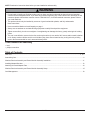
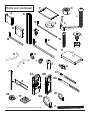
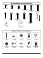
Installation and Assembly:
Wireless TV Cart for 47" to 65" Flat Panel Displays
Models: WL-SR560M-200
Max Load Capacity:
150 lb (68 kg) screen
50 lb (22.7 kg) per shelf
2300 White Oak Circle • Aurora, Il 60502 • (800) 865-2112 • Fax: (800) 359-6500 • www.peerless-av.com
ISSUED: 08-24-12 SHEET #: 180-9037-2 10-30-12
NOTE: Read entire instruction sheet before you start installation and assembly.
WARNING
• Do not begin to install your Peerless product until you have read and understood the instructions and warnings
contained in this Installation Sheet. If you have any questions regarding any of the instructions or warnings, for US
customers please call Peerless customer care at 1-800-865-2112, for all international customers, please contact
your local distributor.
• This product should only be installed by someone of good mechanical aptitude, and fully understands
these instructions.
• Never exceed the Maximum Load Capacity on page 1.
• Always use an assistant or mechanical lifting equipment to safely lift and position equipment.
• Tighten screws firmly, but do not overtighten. Overtightening can damage the items, greatly reducing their holding
power.
• The cart is not affixed or secured to the floor, and may therefore tip over and/or fall if screen and/or stand is shaken
or hit. Always monitor children and do not let children play alone around stand as they could get hurt by a falling
screen. Not recommended for use in areas with heavy traffic.
Tools Needed for Assembly
• level
• phillips screwdriver
Table of Contents
Parts List........................................................................................................................................................................ 3, 4, 5
Assembling Cart .....................................................................................................................................................................6
Wireless Receiver Assembly and Power Module Assembly Installation...............................................................................11
Installing Adapter Brackets ................................................................................................................................................. 12
Attaching Universal Adapter Plate .................................................................................................................................... ...14
Wireless Receiver Assembly and Power Module Assembly Setup.......................................................................................15
Cord Management ............................................................................................................................................................... 18
2 of 19
ISSUED: 08-24-12 SHEET #: 180-9037-2 10-30-12
Before you begin, make sure all parts shown are included with your product.
Parts may appear slightly different than illustrated.
Parts List
A
B
C
D
E
F
G
H
I
J
L
M
N
O
P
Q
R
S
T
U
V
W
X
Z
AA
BB
CC
DD
EE
FF
GG
HH
II
JJ
WL-SR560M-200
Qty. Part Number
1 201-1156
1 201-1157
1 201-1158
1 009-1223
1 201-1110
2 201-1510
1 580-1180
1 590-1210
22 520-2325
10 530-1050
3 520-9550
1 560-9715
2 560-9646
6 530-1038
1 009-1225
1 560-9716
1 009-1296
1 009-1295
2 600-0044
2 600-0045
4 530-1037
4 520-1329
3 540-9424
1 560-0071
1 180-1092
1 180-1015
4 120-1195
4 120-1196
8 530-1021
2 590-9469
8 590-1168
2 560-9711
1 590-9468
4 520-9262
Description
screen mount bracket
hook plate
shelf support
base
universal plate
adapter bracket
upright
top cover
1/4-20 x 12mm decorative screw
1/4-20mm nut
3/8-16 x 2.5" socket screw
7/32" allen wrench
4 mm allen wrench
8/32 nylock nut
shelf pan
6 mm allen wrench
left leg
right leg
wheel caster
wheel caster/brake
joint connector nut
3/8-16 x 1.5" screw bolt
M10 x .402 ID lock washer
3/16 allen wrench
wireless receiver assembly
power module assembly
enclosure mounting bracket, small
enclosure mounting bracket, large
lock nut 1/4-20
cable tie anchor
cable tie .187 x 7.5 lg.
cable tie .04 x 5.75 lg.
cable management sheath
M10 x 15 mm socket screw
3 of 19
ISSUED: 08-24-12 SHEET #: 180-9037-2 10-30-12
Parts List continued
A
P
O
G
L
N
C
X
B
I
JJ
M
W
Q
Z
J
D
R
U
T
S
V
F
AA
BB
H
CC
DD
E
EE
HH
FF
GG
Some parts may appear slightly different than illustrated.
4 of 19
II
ISSUED: 08-24-12 SHEET #: 180-9037-2 10-30-12
Security Adapter Bracket Fasteners
M4 x 12 mm (6)
510-1079
M5 x 12 mm (4)
520-1064
M4 x 25 mm (4)
510-1082
M6 x 30 mm (4)
520-1067
M6 x 12 mm (4)
520-1050
M6 x 25 mm (4)
520-1211
M8 x 15 mm (6)
520-1068
M6 x 20 mm (4)
520-9554
M5 x 25 mm (4)
520-1122
M8 x 25 mm (4)
520-1101
multi-washer (6)
580-1036
M8 x 40 mm (4)
520-1152
I.D. .22" (5.6 mm) (4)
540-1057
I.D. .34" (8.7 mm ) (4)
540-1059
Additional Wireless Components
Quick Start Guide
PRO WIRELESS MULTIMEDIA KIT
®
READY
2
Minutes
Model No. HDS200 (-2, -3, -4)
What’s in the Box
1 x Transmitter
1 x Receiver
2 x Stand
1 x Remote Control
1 x IR Flasher
Step 7 While turning on the display device the HD Flow Pro Wireless Multimedia units will be going through the startup process. This process may
take up to two minutes to complete. The Power/Link indicator lights on the Transmitter and the Receiver will be flashing at first. Flashing indicates
that the units are establishing a secure connection. Wait until the connection is successfully established, indicated by the Power/Link indicator
light becoming solid.
1 x IR Extender
1 x Component Adaptor
2 x Power Adapter
1 x Quick Start Guide
1 x Users Manual
Power/Source
Selection Button
Installation and Setup
Tip The IR window
may be easier to
locate with a direct
light shining on
sections of the
front panel of the
component device.
A small flashlight
works well.
Step 1 Connect the Transmitter to the source devices
(Blu-ray™ Disc player, set top box, gaming console, etc.).
Step 2 Connect the provided IR Flasher to the IR-OUT port on the Transmitter.
Find the location of the IR window on your source device and adhere the
IR Flasher eye directly over the IR window on your source device.
NOTE: One IR Flasher eye is to be used for one component device.
Step 8 Select the output that connects the Receiver to the display using
the Power/Source Selection Button or the provided remote control.
The output indicator light will become solid and the HD Flow logo will
appear on the display device.
Step 9 Turn on the desired source device that is connected to
the Transmitter.
Power/Source
Selection Button
Step 10 Select the desired source or device input on the Transmitter
using the Power/Source Selection Button on the remote control.
Step 11 Play the source device content and enjoy up to Full HD 1080p
wireless entertainment experience.
Troubleshooting Tips
Transmitter and/or Receiver Indicator Lights are all Blinking:
• The HD Flow Pro units are establishing a connection. It can take
up to two minutes for the HD Flow Pro units to establish a complete
connection. If after two minutes have passed and the units have not
established a connection, unplug the power cable, wait 30 seconds
and reconnect the power supply to the units.
Tip Repeat Steps
3-11 to connect
ect
ne
more than one
Receiver unitt
(HDS200-2,
HDS200-3,
HDS200-4).
Step 3 Connectt the
th display
di l device
d i (TV,
(TV monitor,
it projector,
j t etc.)
t )
to the Receiver.
Step 4 Install the IR Extender by plugging in the provided IR Extender in to
the IR-IN port on the Receiver and adhering the other end of the IR Extender
to a vertical surface near the output device. Ensure that the IR Extender is in
a line of sight to the remote control that controls your source devices.
NOTE: For Multicast models, receivers two, three and four do not come with an IR Extender. Additional IR Extenders
(HDS-IRE) can be purchased separately; visit peerless-av.com for more information.
Step 5 Power-up the HD Flow Pro Devices.
1. Plug in the power adapter for the Transmitter and the Receiver to nearby
available power outlets.
2. Plug in the power adapter end to the Transmitter and then to the Receiver.
3. The units will automatically turn-on. The average power-on/sync time
is approximately two minutes.
Transmitter or Receiver Power Indicator Light is OFF:
• Check and verify the power supply connection.
Transmitter Input Indicator Light Blinks:
• Make sure that your source device is turned ON and the cable
is properly connected.
• Verify that the Transmitter is set to the appropriate input port.
• Check the resolution from your source device. This may need to
be changed to a resolution supported by the HD Flow Pro Wireless
Multimedia Kit. Reference the Resolution Chart in the HD Flow Pro
Manual for compatibility. Reference your source devices’ manual
for instruction on changing the output resolution.
Receiver Power Indicator Light Blinks:
• Verify that the HD Flow Pro Transmitter and Receiver are within
the recommended range of 131 feet. Physical obstructions such as
walls, floors and ceilings between the Transmitter and Receiver may
decrease the strength of the connection signal and reduce the overall
transmission range.
Step 6 Turn on your display device (TV, monitor, projector, etc.).
•
Check the media source resolution. The display device must be able
to support the resolution of the media source that is being streamed.
Utilizing the INFO button will allow you to see the resolution data that
the display device supports. If the display device supports the highest
resolution of 720p but the source device is outputting 1080p content,
the content needs to be down-scaled to the maximum resolution of the
display device, in this case 720p.
Receiver Output Indicator Light Blinks:
• Make sure that your display device, source device and the HD Flow Pro units
are all turned ON and the Receiver is properly connected to the output device.
Verify that the Receiver is set to the appropriate output port.
Check the resolution setting of your source device. This may need to be
changed to a resolution supported by the HD Flow Pro unit. Reference
the Resolution Chart in the HD Flow Pro Manual for compatibility.
Reference your source devices’ manual for instruction on changing
the output resolution.
•
•
If the above troubleshooting tips do not resolve the issues for a unicast setup,
please reference the Factory Reset Section of the HD Flow Pro Manual. For a
multicast system configuration, please contact Peerless-AV Customer Care at
800-856-2112 for further instruction.
If a connection has been established and the HD Flow logo can be seen
on the display device, but content is not playing:
• Make sure that the input/output cables are properly connected.
• Verify that the Transmitter is set to the appropriate input port.
© 2012 Peerless Industries, Inc. Peerless-AV™ is a trademark of Peerless Industries, Inc. All rights reserved.
HD Flow™ is a trademark of I Do It, LTD. Other parties’ marks are the property of their respective owners. hdflow.com
wireless transmitter (1) vga to rca adapter (1)
(180-1202)
(180-1006)
plastic stand (1)
(180-1205)
remote (1)
(180-1207)
Warning Do not place the HD Flow
Pro units near other devices that
emit excessive amounts of heat.
Increased temperatures may
cause the HD Flow Pro Transmitter
or Receiver unit to malfunction
or stop working.
Quick Start Guide for HD Flow Pro Wireless Multimedia Kit - LIT-0906
install guide (1)
(LIT-0905)
User Manual and Installation Guide
Pro Wireless Multimedia Kit
Models:
HDS200
HDS200-2
HDS200-3
HDS200-4
®
R E ADY
ISSUED: 06-12-12 SHEET #: 180-9023-1
3v battery (1)
(180-0008)
12v power adapter (1)
(180-1004)
ir flasher (1)
(180-1009)
5 of 19
hdmi cable (2)
(600-0234)
instruction sheet (1)
(180-9023)
ISSUED: 08-24-12 SHEET #: 180-9037-2 10-30-12
1
Insert right leg (S) into base housing (D) as shown in fig. 1.1. Then align holes in right leg with holes in base
housing (D). Fasten base housing to right leg using two 3/8-16 x 1.5" bolts (W) and two joint connectors (V). Tighten
using 3/16" allen wrench (Z) and 7/32" allen wrench (M) as shown in fig.1.2.
NOTE: Left and right legs can be identified by looking at the cart from the front.
Repeat for left side with left leg (R).
fig. 1.1
fig. 1.2
V
D
S
S
FRONT OF CART
W
FRONT OF LEG
2
Insert casters (U & T) into holes of support legs (R & S) and hand thread to secure. Attach casters with brake (U) to
the back of left and right support legs (R & S). Attach casters without brake (T) to front of support legs as shown.
NOTE: Lock brakes on casters to avoid sudden movements during installation.
HAND THREAD
R
S
U
HOLD WHEEL
T
6 of 19
ISSUED: 08-24-12 SHEET #: 180-9037-2 10-30-12
3
Attach upright (G) to base (D), as shown in fig 3.1 using three 3/8-16 x 2.5" socket screws (L) and M10 x .402ID
lock washers (X). Tighten screws using 7/32" allen wrench (M).
NOTE: Be sure cord management holes are in the configuration shown in fig 3.2.
fig. 3.1
fig. 3.2
G
CORD MANAGEMENT
HOLES
D
X
L
4
Loosely attach four 1/4-20 x 12 mm screws (I) and 1/4-20 nuts (J) to shelf support (C).
J
I
C
7 of 19
ISSUED: 08-24-12 SHEET #: 180-9037-2 10-30-12
5
Slide shelf support (C) onto upright (G) so that 1/4-20 nuts (J) slide into slots of upright (G) as shown in figure 5.1
and detail 1. Slide shelf support to desired height, level, then tighten 1/4-20 x 12mm screws (I) using 4 mm allen
wrench (N).
NOTE: MAXIMUM OF TWO SHELVES
Max height of top shelf is 34" from base.
Max height of second shelf is 28" from base.
C
J
G
SLOT
DETAIL 1
fig. 5.1
8 of 19
ISSUED: 08-24-12 SHEET #: 180-9037-2 10-30-12
Attaching Metal Shelf
6
Attach shelf pan (P) to shelf support (C) using six 8/32 nylock nuts (O) as shown below. Use an adjustable wrench
to tighten six 8/32 nylock nuts (O).
WARNING
• This shelf is intended for use with equipment weighing
NO more than 50 lbs. (22.7 kg) that fits evenly accross
the surface of shelf pan (P). Use with other equipment
may result in instability and cause personal injury or
property damage.
P
C
O
9 of 19
ISSUED: 08-24-12 SHEET #: 180-9037-2 10-30-12
7
Loosely attach six 1/4-20 x 12 mm screws (I) and
1/4-20 nuts (J) to screen mount bracket (A).
Slide screen mount bracket (A) onto upright (G) so
that 1/4-20 nuts (J) slide into slots of upright (G) as
shown in figure 8.1 and detail 2. Slide screen mount
bracket to desired position, level, then tighten 1/4-20
x 12 mm screws (I) using 4 mm allen wrench (N).
8
A
J
J
I
G
I
DETAIL 2
SLOT
A
G
fig. 8.1
9
Snap top cover (H) onto upright (G).
10
Insert two 1/4-20 x 12 mm screws (I) into screen
mount bracket (A), leaving 3/16" of exposed thread
as shown in figure 10.1 and detail 3.
H
I
3/16"
G
A
DETAIL 3
fig. 10.1
10 of 19
ISSUED: 08-24-12 SHEET #: 180-9037-2 10-30-12
Wireless Receiver and Power Enclosure Installation
NOTE: For mounting patterns smaller than VESA 400, use large enclosure mounting bracket (DD).
11
NOTE: The Wireless Receiver Assembly (AA) and Power Module Assembly (BB) position can be interchanged
based on the display’s connector panel location. Install Wireless Receiver Assembly on the side closest to the
connector panel.
Loosely attach the enclosure mounting brackets (CC or DD) to the wireless receiver assembly (AA) with two
1/4-20 x 12 mm screws (I) and two 1/4-20 nuts (EE) as shown in fig. 11.1. NOTE: The enclosure mounting bracket
can be installed with the inside notch facing downward if additional side-to-side adjustment is needed. Attach the
mounting brackets (CC or DD), open end of notch facing downward, to the adapter bracket (F) with two
1/4-20 x 12 mm screws (I) and two 1/4-20 nuts (EE) as shown in fig. 11.2.
Adjust the position of the receiver assembly (AA) to your desired location as shown in fig. 11.2. Once in position,
tighten the four 1/4-20 x 12 mm screws (I) using 4mm allen wrench (N).
I
AA
EE
I
EE
CC or
DD
F
fig. 11.1
AA
INSIDE NOTCH
12
INSIDE NOTCH
fig. 11.2
NOTE: For mounting patterns smaller than VESA 400, use large enclosure mounting bracket (DD).
Loosely attach the enclosure mounting brackets (CC or DD) to the power module assembly (BB) with two
1/4-20 x 12 mm screws (I) and two 1/4-20 nuts (EE) as shown in fig. 12.1. NOTE: The enclosure mounting
bracket can be installed with the inside notch facing downward if additional side-to-side adjustment is needed.
Attach the mounting brackets (CC or DD), open end of notch facing downward, to the adapter bracket (F) with two
1/4-20 x 12 mm screws (I) and two 1/4-20 nuts (EE) as shown in fig. 12.2.
Adjust the position of the power module assembly (BB) to your desired location as shown in fig. 12.2. Once in
position, tighten the four 1/4-20 x 12 mm screws (I) using 4mm allen wrench (N).
EE
BB
BB
CC or
DD
EE
I
INSIDE NOTCH
F
fig. 12.1
11 of 14
I
fig. 12.2
ISSUED: 11-14-11 SHEET #: 180-9007-1
Installing Adapter Brackets to Universal Plate
WARNING
• Tighten screws so adapter brackets are firmly attached. Do not tighten with excessive force. Overtightening can
cause stress damage to screws, greatly reducing their holding power and possibly causing screw heads to become
detached. Tighten to 40 in. • lb (4.5 N.M.) maximum torque.
• If screws don't get three complete turns in the screen inserts or if screws bottom out and bracket is still not tightly
secured, damage may occur to screen or product may fail.
13
To prevent scratching the screen, set a cloth on a flat, level surface that will support the weight of the screen. Place
screen face side down. Refer to screen manufacturers instructions or customer service, for removing any knobs,
base, cover, or screw(s) on the back of the screen to prepare mounting. These need to be removed to allow the
adapter brackets to be attached.
Position adapter brackets (F) over mounting holes on back of screen. Adjust the position of assemblies
(AA and BB) so that they are at least 32" apart. Make sure assemblies (AA and BB) are evenly spaced from the
adapter brackets. Tighten screws (I) to lock position of assemblies (AA and BB).
Select the small, medium, large or extra large screws from the baffled fastener pack then attach adapter brackets to
screen following figure 13.1.
NOTE: Top and bottom mounting holes must be used for attaching brackets. Verify that all holes are properly
aligned, and then tighten screws using a security allen wrench.
32" Min.
X
BB
AA
CENTER BRACKETS
VERTICALLY ON BACK
OF SCREEN
Y
Y
X
NOTE: "X" dimensions should be equal.
NOTE: "Y" dimensions should be equal.
Notes:
MULTI-WASHER
• The number of fasteners used will vary,
depending upon the type of screen.
• Multi-washers and spacers may not be
used, depending upon the type of screen.
MEDIUM HOLE FOR M5 SCREWS
SMALL HOLE FOR M4 SCREWS
LARGE HOLE FOR M6 SCREWS
• Use the corresponding hole in the multiwasher that matches your screw size as
shown.
12 of 19
ISSUED: 08-24-12 SHEET #: 180-9037-2 10-30-12
13-1
Begin with longer length screw, hand thread through multi-washer, adapter bracket and spacer in that order into
screen as shown below. Screw must make at least three full turns into the mounting hole and fit snug into place.
Do not over tighten. If screw cannot make three full turns into the screen, select a shorter length screw from the
baffled fastener pack. Repeat for remaining mounting holes, level brackets and tighten screws.
fig. 13.1
SCREEN
MULTI-WASHER
SPACER
SCREW
ADAPTER
BRACKET (F)
If you have any questions, please call Peerless customer care at 1-800-865-2112.
13 of 19
ISSUED: 08-24-12 SHEET #: 180-9037-2 10-30-12
Attaching Universal Adapter Plate
14
Attach Universal Plate (E) to hook plate (B) using
four M10 x 15 mm socket screws (JJ). Tighten
screws using 6 mm allen wrench (Q).
15
Attach hook plate (B) to screen mount bracket (A).
B
E
B
A
JJ
16
Insert two 1/4-20 x 12 mm screws (I) into holes indicated below for desired screen orientation. Tighten all screws
using 4 mm allen wrench (N).
I
I
No Tilt
2° Backward Tilt
14 of 19
I
5° Forward Tilt
ISSUED: 08-24-12 SHEET #: 180-9037-2 10-30-12
Wireless Receiver Assembly and Power Module Assembly Setup
17
Remove the two #8 screws securing the cover of the wireless receiver assembly (AA) as shown in detail 4. Open
the enclosure to expose the wireless receiver and IR unit. Remove the M5 x 10mm phillips screws and open the
power module assembly (BB) as shown in detail 5.
M5 X 10mm SCREWS
BB
AA
#8 SCREW
DETAIL 4
18
DETAIL 5
Untie the wireless receiver power adapter cord and route as shown below. Plug the end of the power adapter into
the outlet marked DC on the wireless receiver as shown in detail 6. Coil up the excess cord and secure with a
cable tie (HH). Store the coiled cord between the power adapter and the power module wall as shown.
WIRELESS RECEIVER POWER
ADAPTER
DISPLAY NOT
SHOWN FOR
CLARITY
US
B
LA
N
DC
DETAIL 6
15 of 19
ISSUED: 08-24-12 SHEET #: 180-9037-2 10-30-12
19
Locate the IR receiver inside of the wireless receiver enclosure shown in figure 19.1. Remove the tie from the cable
and position the IR receiver on the display within line of sight of your remote as shown in figure 19.2. Remove the
adhesive backing from the IR receiver eye and attach to the display. Coil up the excess cord near the wireless
receiver enclosure (AA) and secure with a cable tie (HH). Store the coiled cord back inside of the enclosure.
fig. 19.2
IR RECIEVER
IR RECIEVER
20
fig. 19.1
Close the top cover of the wireless receiver assembly (AA), making sure that the power adapter cords run
underneath the cable opening as shown below. Re-install the two #8 screws.
#8 SCREWS
CABLE OPENING
16 of 19
ISSUED: 08-24-12 SHEET #: 180-9037-2 10-30-12
21
Install the cable tie anchor (FF) onto the inside
back wall of the power enclosure (BB). Remove the
adhesive backing from the anchor and press into
place in the area shown.
22
FF
Plug the power cord from your display into the triple
tap grounded outlet as shown. Coil up the excess
cord and secure with a cable tie (GG), inserting it
through the cable tie anchor (FF) and around the
coiled cord.
TRIPLE TAP
GROUNDED OUTLET
DISPLAY POWER
CORD
GG
23
Close the top cover of the power module assembly
(BB), making sure that the power adapter cords run
underneath the cable opening as shown below.
Re-install the M5 x 10mm phillips screws.
24
Place the cords inside the cable management sheath
(II) by pushing the cables through the slit in the
sheath. NOTE: The sheath may need to be trimmed
to length before installing cords.
II
M5 x 10mm SCREWS
CABLE
OPENING
25
Plug the component cable(s) from your display
(HDMI shown) into the wireless receiver.
COMPONENT
CABLE
HD
26
Plug extension cord (not included) into power adapter.
M
I-O
UT
EXTENSION CORD
17 of 19
ISSUED: 08-24-12 SHEET #: 180-9037-2 10-30-12
Mounting and Removing Flat Panel Screen
WARNING
• Always use an assistant or mechanical lifting equipment to safely lift and position the plasma television.
27
Hook adapter brackets (F) onto universal plate (E),
then slowly swing screen in as shown. Turn
screws of adapter plate (F) clockwise at least six
times to prevent screen from being removed as
shown in detail 7.
NOTE: Tighten using 4 mm allen wrench (N).
Screen can be adjusted horizontally if desired.
E
SCREWS
NOTE: It is important to lock screen down! To
lock the screen down, fully tighten screws to adapter
bracket as shown in detail 7.
E
F
To remove screen from mount, loosen screws,
swing screen away from mount, and lift screen off of
mount.
DETAIL 7
F
Cord Management
28
Run extension cord (not included) through upright (G) using cord
management holes.
CORD
MANAGEMENT
G
29
To complete the installation of your wireless mount, please refer to the HD Flow™ User's Manual and the HD
Flow™ Install Guide included.
18 of 19
ISSUED: 08-24-12 SHEET #: 180-9037-2 10-30-12
© 2012 Peerless Industries, Inc.
Peerless-AV® is a registered trademark of Peerless Industries, Inc. All rights reserved.
All other brand and product names are trademarks or registered trademarks of their respective owners.
LIMITED WARRANTY
Peerless Industries, Inc. (“Peerless-AV®”) warrants to original end-users of Peerless-AV® products that Peerless-AV® products will be free from defects in material
and workmanship, under normal use, for the periods listed below, from the date of purchase by the original end-user. At its option, Peerless-AV® will repair or
replace with new or refurbished products or parts, or refund the purchase price of any Peerless-AV® product which fails to conform with this warranty.
In no event shall the duration of any implied warranty of merchantability or fitness for a particular purpose be longer than the period of the applicable
express warranty set forth above. Some states do not allow limitations on how long an implied warranty lasts, so the above limitation may not apply to you.
This warranty does not cover damage caused by (a) service or repairs by the customer or a person who is not authorized for such service or repairs by PeerlessAV®, (b) the failure to utilize proper packing when returning the product, (c) incorrect installation or the failure to follow Peerless-AV®’s instructions or warnings
when installing, using or storing the product, or (d) misuse or accident, in transit or otherwise, including in cases of third-party actions and force majeure. This
warranty also does not cover corrosion or rust resulting from damaged, scratched or chipped paint or other surfaces.
In no event shall Peerless-AV® be liable for incidental or consequential damages or damages arising from the theft of any product, whether or not
secured by a security device which may be included with the Peerless-AV® product. Some states do not allow the exclusion or limitation of incidental or
consequential damages, so the above limitation or exclusion may not apply to you.
This warranty is in lieu of all other warranties, express or implied, and is the sole remedy with respect to product defects. No dealer, distributor, installer or other
person is authorized to modify or extend this Limited Warranty or impose any obligation on Peerless-AV® in connection with the sale of any Peerless-AV® product.
This warranty gives specific legal rights, and you may also have other rights which vary from state to state.
Product
Warranty Period
Mounts
Furniture
Cables
Cleaning Products
Electronic Products and components
5 years
1 year
25 years
1 year
1 year
www.peerless-av.com
19 of 19
© 2012 Peerless Industries, Inc.
ISSUED: 08-24-12 SHEET #: 180-9037-2 10-30-12