1
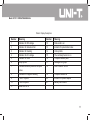
Model UT511
OPERATING MANUAL
Model UT511: OPERATING MANUAL
TITLE
Introduction
Unpacking the Meter
Safety Information
International Electrical Symbols
Battery Saver (Sleep Mode)
Battery Indication
The Meter Structure
Display
Key Functions
Measurement Operation
A.Measuring Voltages
B.Measuring Insulation Resistance
a) Continuous Measurement
b) Timed Measurement
c) Polarization Index (PI) Measurement
d) Compare Function
C. Low Resistance Measurement
PAGE
5
5
5
7
8
8
9
10
12
15
15
16
17
18
18
19
20
1
Model UT511: OPERATING MANUAL
TITLE
The Use of Power Adaptor
Maintenance
A. General Service
B. Replacing the Battery
Specifications
Safety and Compliances
Physical Specifications
General Specifications
Feature Summary
Detailed Accuracy Specifications
A. Voltage Measurement
B. Insulation Resistance Measurement
C. Low Resistance Measurement
2
PAGE
21
22
22
22
24
24
24
25
25
26
26
26
27
Model UT511: OPERATING MANUAL
Table
Title
1.
2.
3.
4.
5.
6.
7.
Unpacking Inspection
International Electrical Symbols
Battery Indication
Meter Front Description
Meter Side Description
Display Description
Key Description
Page
5
7
8
9
10
11
12
3
Model UT511: OPERATING MANUAL
4
Figure
Title
1.
2.
3.
4.
5.
6.
7.
8.
The Meter Front Structure
The Meter Side Structure
The Display
Voltage Measurement
Insulation Resistance Measurement
Low Resistance Measurement
The Use of Power Adaptor
Battery Replacement
Page
9
10
10
15
16
20
21
23
Model UT511: OPERATING MANUAL
Introduction
Uni-Trend Model UT511 insulation resistance tester
(hereafter, “the Meter”) is a handheld instrument
designed primarily to make resistance/ insulation
resistance measurement.
Unpacking the Meter
The Meter includes the following items:
Table 1. Unpacking Inspection
Item
1
2
3
4
5
6
Description
English Operating Manual
One plug test lead to one alligator
Two plugs test lead to one
alligator
1.5V Battery (R14 or LR14)
Tool Box
Power adaptor (optionally,
available at extra cost)
Qty
1 piece
2 pieces
1 piece
8 pieces
1 piece
1 piece
In the event you find any missing or damage, please
contact your dealer immediately.
Safety Information
This Meter complies with the standards IEC61010 safety
measurement requirement: in pollution degree 2,
overvoltage category (CAT. III 600V, CAT.II 1000V) and
double insulation.
CAT II: Local level, appliance, PORTABLE EQUIPMENT
etc., with smaller transient voltage overvoltages than
CAT. III
CAT III: Distribution level, fixed installation, with smaller
transient overvoltages than CAT. IV
Use the Meter only as specified in this operating manual,
otherwise the protection provided by the Meter may be
impaired.
Danger identifies conditions and actions that pose
hazard(s) to the user.
Warning identifies avoiding electric shock.
Caution identifies conditions and actions that may
damage the Meter and carrying out accurate
measurement.
5
Model UT511: OPERATING MANUAL
International electrical symbols used on the Meter and
in this Operating Manual are explained on page 4~5.
Danger
Use of instrument in a manual not specifed by
the manufactuer may impair safety features/
protection provided by the equipment. Read the
following safety information carefully before using
or servicing the instrument.
l Do not apply more than 1000VDC or 750V AC.
l Do not use the Meter around explosive gas,
vapor or dust.
l Do not use the Meter in a wet environment.
l When using the test leads, keep your figures
away from the lead contacts. Keep your
figures behind the finger guards on the leads.
l Do not use the Meter with any parts or cover
removed.
l When carrying out insulation measurement,
do not contact the circuit under test.
6
Warning
l Do not use the Meter if it is damaged or metal
part is exposed. Look for cracks or missing
plastic.
l Be careful when working above 30V rms, 42V
ac rms and 60V DC. Such voltages pose a
shock hazard.
l Discharge all loading of circuit under test after
measuring high voltage.
l Do not change battery when the Meter is in
wet environment.
l Place test leads in proper input terminals.
Make sure all the test leads are firmly
connected to the Meter’s input terminals.
Make sure the Meter is turned off when
opening the battery compartment.
Caution
l When performing resistance tests, remove all
power from the circuit to be measured and
discharge all the power.
Model UT511: OPERATING MANUAL
l When servicing the Meter, use only the same
model number or identical electrical
specifications of test leads and power adaptor.
l Do not use the Meter if the battery indicator
(
) shows a battery empty condition. Take
the battery out from the Meter if it is not used
for a long time.
l Do not use or store the Meter in an
environment of high temperature, humidity,
explosive, inflammable and strong magnetic
field. The performance of the Meter may
deteriorate after dampened.
l Soft cloth and mild detergent should be used
to clean the surface of the Meter when
servicing. No abrasive and solvent should be
used to prevent the surface of the Meter from
corrosion, damage and accident.
Dry the Meter before storing if it is wet.
International Electrical Symbols
International symbols on the Meter and in this manual
are explained in Table 2.
Table 2. International Electrical Symbols
Risk of electric shock
Equipment protected by double or
reinforced insulation.
DC Measurement
AC Measurement
Grounding
See Manual
Empty of Built-In Battery
Conforms to Standards of European Union
7
Model UT511: OPERATING MANUAL
Battery Saver (Sleep Mode)
Battery Indication
The Meter enters the Sleep Mode and blanks the display
if there is no button press for 15 minutes. This is done
to conserve battery power. The Meter comes out of
Sleep Mode when ON/OFF button is pressed two times.
There is a battery indicator shows on the display upper
left hand corner. Below Table 3 is the explanation:
The 15 minutes timer is disabled during any insulation
resistance measurement. The time period starts
immediately following any measurement.
8
Table 3. Battery Indication
Battery
Indicator
Battery Voltage
8.5V or less. It means the battery is
empty, don’t use the Meter as it cannot
guarantee accuracy.
8.6V~9.0V. It means the battery is nearly
empty, replacing battery is necessary.
Accuracy will not be affected.
9.1V~10.2V
10.3V or more
Model UT511: OPERATING MANUAL
The Meter Structure
Below Figure 1 and Table 4 shows the Meter front
structure and description
Table 4. Meter Front Description
1
2
3
4
5
6
7
8
9
10
LCD
Scroll Button
Emergency stop
Data Clear the
Display Backlight
Button,
Down Button
On/Off Button
Compare Button
Insulation Resistance
Button
Voltages
measurement Button
Timer Button.
Figure 1. The Meter Front Structure
11
Low Resistance
measurement Button
12
13
14
15
Test Button
Step Button
Data Store Button.
Data Recall Button
16
Scroll Button
17
Up Button
18 LINE: Resistance
input terminal
19 COM: Voltage input
terminal
20 EARTH: Resistance
input terminal
21 V: Voltage input
terminal
22 Testing leads
9
Model UT511: OPERATING MANUAL
Below Figure 2 and Table 5 shows the Meter side
structure and description
Display
Table 6 and Figure 3 describe the display.
Figure 2. The Meter Side Structure (Side View)
Figure 3. Display
Table 5. Meter Side Description
10
1
Safety Shutter
2
Power adaptor Input Terminal
Model UT511: OPERATING MANUAL
Table 6. Display Description
Number
1
2
3
4
5
6
7
8
9
10
11
Meaning
Indicator for DC voltage
Indicator for data store full
Indicator for clearing
Indicator for AC voltage
Indicator for timer
Step symbol
Indicates selected pass/fail compare
value
Indicates for negative reading
Timer 1 symbol
Timer 2 symbol
Data store is on
Number
12
13
14
15
16
17
18
Meaning
Data recall is on
Indicator for polarization index
Unit symbols
The continuity buzzer is on
Compare feature pass
Analogue bar graph
Risk of electric shock
19
20
21
Compare feature fail
Indicator for power adaptor
Battery life indicator
11
Model UT511: OPERATING MANUAL
Key Functions
Table 7. Key Description
ON/OFF
CLEAR/
SAVE
LOAD
12
Turn on or off the Meter. Press and hold
the button for 1 second to turn the Meter
on.
Press to clear the stored data,Push 1
SEC to turn on and off the display
backlight.
Press to store the current measurement
value. The maximum number of stored
reading is 18. When the stored readings
memory is full, the Meter shows FULL
and stop storing. Press CLEAR to clear
the stored value in order to store the
next measurement value.
l Press once to recall the first stored
value.
l Press again to exit Load feature.
l Load feature can only be used when
there is no high voltage output.
l Under insulation resistance measurement
mode: press to select one voltage
range up.
l Under load mode: press to recall
the previous stored value.
l Under insulation resistance measurement
mode: press to select one voltage
range down.
l Under load mode: press to recall
the next stored value.
l When set the timer duration for the
measurement of insulation resistance
or polarization index, press to
decrement the time. The maximum
length of time is 30 minutes, the
Meter will automatically carry out
measurement.
Model UT511: OPERATING MANUAL
Table 7. Key Description
l When compare feature measuring
insulation resistance, press to
decrement a resistance comparing
value.
l After polarization index measurement,
press to display polarization index,
TIME 2 insulation resistance value
and TIME 1 insulation resistance
value in sequence.
l When set the timer duration for the
measurement of insulation resistance
or polarization index, press to
increment the time. The maximum
length of time is 30 minutes, the Meter
will automatically carry out
measurement.
l When use the compare feature
measuring insulation resistance, press
to increment a resistance comparing
value.
l After polarization index measurement,
press to display polarization index,
TIME 2 insulation resistance value
and TIME 1 insulation resistance
value in sequence.
STEP
Press to display S1 S2
S3 in
sequence.
l When the Meter is under timed
measurement or polarization index
measurement:
S1 means increment of 1, then
each press of increase 1 or
decrease 1.
S2 means increment of 10, then
each press of increase 10 or
decrease 10.
S3 means increment of 30, then
each press of increase 30 or
decrease 30.
13
Model UT511: OPERATING MANUAL
Table 7. Key Description
STEP
COMP
TIME
TEST
Ho
14
l When the Meter is under compare
mode:
S1 means increment of 1, then
each press of increase 1 or
decrease 1.
S2 means increment of 10, then
each press of increase 10 or
decrease 10.
S3 means increment of 100, then
each press of increase 100 or
decrease 100.
Set a pass / fail limit for insulation tests.
The default value is 100M
Pres to step through continuous
measurement, timed measurement and
polarization index measurement in
sequence.
Press to stop or start an insulation
resistance test
Press to initiate insulation resistance
measurement
Lo
DVC
/ACV
Press to initiate low resistance
measurement
Pres to initiate voltages measurement
E-STOP Emergency stop button. Press this
button when the Meter is hang and
cannot turn off the power.
Model UT511: OPERATING MANUAL
Measurement Operation
Below section explains how to make measurements.
A. Measuring Voltages
Caution
l Special care should be taken when measuring
high voltage.
Warning
l To avoid harms to you or damages to the Meter,
please do not attempt to measure voltages
higher than 1000V DC or 750V AC, although
readings may be obtained.
Black
To measure voltages, set up the Meter as Figure 4 and
do the following:
Red
Figure 4. Voltages Measurement
1. Press DCV or ACV button to select DC voltage or
AC voltage measurement
2. Insert the red test lead into the V terminal and the
black test lead into the COM terminal.
3. Connect the red and black alligator clip to the circuit
to be measured.
4. During measurement, when the red test lead is
negative voltage, then “-“ shows on the display.
15
Model UT511: OPERATING MANUAL
Note
l When voltage measurement has been completed,
disconnect the connection between the testing
leads and the circuit under test and remove testing
leads away from the input terminals of the Meter.
B. Measuring Insulation Resistance
Red
Black
Figure 5. Insulation Resistance Measurement
16
Model UT511: OPERATING MANUAL
Caution
l When performing insulation resistance tests,
remove all power from the circuit to be measured
and discharge all the power.
l Do not short circuit two test leads under high
voltage status.
l Do not measure insulation resistance after high
voltage output.
l Do not measure over 10 seconds when:
100V measure resistance lower than 500k
250V measure resistance lower than 1M
500V measure resistance lower than 2M
1000V measure resistance lower than 5M
l When the measurement is completed, don’t
touch the circuit as the circuit has already stored
capacitance which may cause electric shock.
l Don’t touch the test leads even after it has been
removed from the circuit until voltages are all
released.
To measure insulation resistance, set up the Meter as
Figure 5 and do the following:
1. Press HO button to select insulation resistance
measurement.
2. Press and button to select voltages of 100V,
250V, 500V or 1000V.
3. Insert the red test lead into the LINE terminal and
the black test lead into EARTH terminal.
4. Connect the red and black alligator clip to the circuit
to be measured, positive voltage output from LINE
terminal.
5. Choose below insulation resistance measurement
mode.
l Press TIME button to select continuous
measurement mode, there is no timer icon on
the LCD.
l Press and hold TEST button for 1 second to
carry out continuous measurement. Output
insulation resistance testing voltage, TEST button
light up, blinks on every 0.5 seconds.
17
Model UT511: OPERATING MANUAL
Press TEST button to close the insulation resistance
measurement voltage when measurement is
completed. TEST button lights off
, disappears.
The LCD shows the current insulation resistance
measurement value.
l Press TIME button to select timed measurement
mode, the LCD displays TIME 1 and symbols.
l Press
, and STEP buttons to set the time
(00:05~29:30).
l Then press and hold TEST button for 1 second to
carry out timed measurement. TIME 1 and are
displayed and blinked on the LCD on every 0.5
seconds.
l When the set time is reached, the insulation
resistance measurement voltage will be closed and
the measurement will be automatically stopped.
The LCD displays the insulation resistance reading.
18
l Press TIME button to select timed measurement
mode, the LCD displays TIME 1 and symbols.
l Press
, and STEP buttons to set the time
(00:05~29:30).
l Press TIME button again. TIME 2, PI and symbols
appear on the LCD.
l Press
, and STEP buttons to set the time
(00:10~30:00).
l Then press and hold TEST button for 1 second to
carry out timed measurement.
l TIME 1 and are displayed and blinked on the
LCD on every 0.5 seconds before TIME 1 set time
is reached.
l TIME 2 and are displayed and blinked on the
LCD on every 0.5 seconds before TIME 2 set time
is reached.
l When the two set time are reached, the insulation
resistance measurement voltage will be closed and
the measurement will be automatically stopped.
The LCD displays the polarization index reading.
Model UT511: OPERATING MANUAL
l Press
, to set through the polarization index,
TIME 2 insulation resistance reading and TIME 2
insulation resistance reading.
Information:
PI = 3 minutes ~10 minutes reading / 30 second ~1
minutes reading
PI
4 or more 4~2
Standard The best Good
2.0~1.0
Warning
1.0 or less
Bad
l Press COMP button to select compare feature.
COMP symbol displays on the LCD.
l Press
, and STEP buttons to set the compare
value. The minimum value is 1M The maximum
value is the maximum tested voltage allowable
measurement value.
l Press and hold TEST button for 1 second to carry
out the measurement.
l The NG symbol will display if the insulation resistance
value is smaller than resistance value. Otherwise
GOOD symbol will be displayed.
19
Model UT511: OPERATING MANUAL
C. Low Resistance Measurement
Caution
l When performing insulation resistance tests,
remove all power from the circuit to be measured
and discharge all the power.
Red
To measure low resistance, set up the Meter as Figure
6 and do the following:
Black
Figure 6. Low Resistance Measurement
20
1. Press LO button to select low resistance
measurement..
2. Insert the red test lead into the LINE terminal and
the black test lead into EARTH terminal.
3. Connect the red and black alligator clip to the circuit
to be measured. When the resistance is less than
30 the buzzer sounds.
4. This range can test LED diode. Connect the anode
LED diode to the red test lead, the LED diode will
light up if it is good. If the LED diode does not light
up, it means it is damaged.
Model UT511: OPERATING MANUAL
The Use of Power Adaptor
The use of power adaptor, see figure 7
1. Open the side safey shutter, then you will see there
is a power adaptor input terminal.
2. Make sure the Meter is power off and Insert the
UT511 power adaptor to the input terminal.
3. It is highly recommed to take out all the batteries
when you are using the power adaptor.
4. Make sure the Meter is power off when you
disconnect the UT511 power adaptor from the Meter.
(Input voltage 230VAC, Frequency 50/60Hz, Input
current 50mA, Output voltage DC 15V, MAX current
600mA)
Caution
If you want to choose power adaptor for power supply,
please use special power adaptor SA48-150060EU
which supported by our company, otherwise it will be
dangerous.
Figure 7. The Use of Power Adaptor
21
Model UT511: OPERATING MANUAL
Maintenance
This section provides basic maintenance information
including battery replacement instruction.
Warning
Do not attempt to repair or service your Meter unless
you are qualified to do so and have the relevant
calibration, performance test, and service
information.
A. General Service
l Periodically wipe the case with a damp cloth and
mild detergent. Do not use abrasives or solvents.
l To clean the terminals with cotton bar with detergent,
as dirt or moisture in the terminals can affect readings.
l Turn the Meter to OFF when it is not in use.
l Take out the battery when it is not using for a long
time.
l Do not use or store the Meter in a place of humidity,
high temperature, explosive, inflammable and strong
magnetic field.
l If the Meter is wet, dry it before use.
22
B. Replacing the Battery
Warning
To avoid electric shock, remove all the test leads
from the Meter when replacing the batteries.
Caution
l Don’t mix to use old and new batteries.
l Be careful the polarity is correct when installing
batteries.
l Do not use the Meter if the battery indicator
(
) shows a battery empty condition.
Model UT511: OPERATING MANUAL
Follow Figure 8 and proceed as follows to replace the
battery:
l Turn the Meter to OFF and remove all connections
from the terminals.
l Remove the screw from the battery compartment,
and separate the battery compartment from the
case bottom.
l There are 8pcs of 1.5V (R14) carbon battteries in
the meter, except this, it can support 1.5V (LR14)
alkalescence batteries and the special power apapter
which our company provided.
l Rejoin the case bottom and battery compartment,
and reinstall the screw.
Figure 8. Battery Replacement
23
Model UT511: OPERATING MANUAL
Specifications
Safety and Compliances
Certification
Compliances
IEC 61010 CAT.II 1000V, CAT.III 600V overvoltage and double insulation standard
Physical Specifications
Display (LCD)
Operating Temperature
Storage Temperature
Relative Humidity
Battery Type
Dimensions (HxW xL)
Weight
24
Digital: 9999 counts
Analog bar graph.
-10 ~40 (14 ~104 )
-20 ~60 (-4 ~140 )
85% @ -10 ~40 below;
90% @ -20 ~60 :
8pcs of 1.5V (R14 or LR14) batteries or DC15V power adaptor. DC15V
power adaptor is optionally at extra cost.
202 x 155 x 94 mm
Approx. 2kg (including battery)
Model UT511: OPERATING MANUAL
General Specifications
Range
Overloading
Battery Indicator
Icon Display
Current Consumption
Auto
Display OL on insulation resistance range
Display
Equips with function and battery indicator icons.
Maximum: around 90mA
Average: around 20mA
Feature Summary
Display Backlight
Autorange
Warning
Voltage
COMP Measurement
PI Measurement
Bright backlight for clear readings in poorly lighted areas.
The Meter automatically selects best range
and red light will on.
Auto release voltage
Use the Compare function to set a pass/fail compare level for the insulation
measurements.
Polarization Index is the ratio of insulation resistance. You can pre-set two
point of times and automatically carry out the measurement.
25
Model UT511: OPERATING MANUAL
Detailed Accuracy Specifications
Accuracy: ([% of reading] + [number of least significant digits), guarantee for 1 year.
Operating temperature: 18 ~28
Relative humidity: 45~75%RH
A. Voltage Measurement
Measurement Range
Resolution
Accuracy
DC Voltage
30 ~ 1000V
1V
(2%+3)
AC Voltage
30V~750V (50/60Hz)
30~100V (2%+5)
100~750V (2%+3)
B. Insulation Resistance Measurement
Output Voltage
Display Range
100V
0.1M ~99.9M
100~500M
Open Circuit Voltage DC100V + 20%,-0%
Test Current
1mA~1.2mA@100k
Short Circuit
Accuracy
100k
26
250V
0.5M ~99.9M
100~999M
1.00~1.99G
DC250V + 20%, -0%
1mA~1.2mA@250k
to 100M
500V
1M ~99.9M
100~999M
1.00~3.99G
DC 500V + 20%, -0%
1mA~1.2mA@500k
Around 2.0mA
: (3%+5) 100M
above: (5%+5)
1000V
2M ~99.9M
100~999M
1.00~10.00G
DC1000V + 20%, -0%
1mA~1.2mA@1M
Model UT511: OPERATING MANUAL
Caution
At any output voltage, when the tested resistance is les than 5MΩ, the testing time cannot exceed 10 seconds.
C. Low Resistance Measurement
Function
Measurement Range
Resolution
Accuracy
Maximum open circuit voltage
Buzzer
Overload Protection
Resistance
0.1Ω~999.9Ω
0.1Ω
(1%+3)
Around 2.8V
Open at less than 30Ω
220V rms/10 seconds
27
Model UT511: OPERATING MANUAL
*END*
This operating manual is subject to change without notice.
28
Model UT511: OPERATING MANUAL
Copyright 2006 Uni-Trend Group Limited.
All rights reserved.
Manufacturer:
Uni-Trend Technology (Dongguan) Limited
Dong Fang Da Dao
Bei Shan Dong Fang Industrial Development District
Hu Men Town, Dongguan City
Guang Dong Province
China
Postal Code: 523 925
Headquarters:
Uni-Trend Group Limited
Rm901, 9/F, Nanyang Plaza
57 Hung To Road
Kwun Tong
Kowloon, Hong Kong
Tel: (852) 2950 9168
Fax: (852) 2950 9303
Email: [email protected]
http://www.uni-trend.com
29