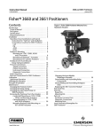
1
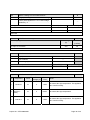
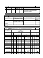
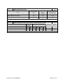
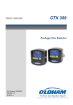
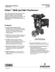
TEST REPORT
EN 50291: 2001
Electrical apparatus for the detection of carbon monoxide in domestic premises
Test methods and performance requirements
Report reference No . ...................... : STR10088038S
Tested by (name+ signature) .......... : Billy Tu
Compiled by (+ signature)............... : Fred zou
Approved by (+ signature) ............... : Ailis Ma
Date of issue ................................... : August 21, 2010
Total number of pages ..................... : 35 Pages.
Testing laboratory ......................... : SEM.Test Compliance Service Co., Ltd.
Address ........................................... : 3/F, Jinbao Commerce Building, Xin'an Fanshen Road, Bao'an
District, Shenzhen, P.R.C. (518101)
Testing location ............................... : As above
Applicant’s name .......................... : Ningbo Wanke Electron Technology Co., Ltd.
Address ........................................... : WanTai Industry City, Shipu, Xiangshan, Zhejiang Province, China.
Manufacturer’s name ..................... Ningbo Wanke Electron Technology Co., Ltd.
Address ........................................... : WanTai Industry City, Shipu, Xiangshan, Zhejiang Province, China.
Test specification…………………..:
Standard........................................... : EN 50291: 2001
Test procedure ................................ : Type Approval
Procedure deviation ........................ : N/A
Non-standard test method .............. : N/A
This test report is specially limited to the above client company and product model only. It may not
be duplicated without prior written consent of SEM.Test.
Test item description .................... : CARBON MONOXIDE DETECTOR
Trademark ....................................... : N/A.
Model/type reference .................... : XC-05, XC-06
Ratings ............................................. : DC 9V, 50mA
Project No.: STR10088038S
Page 1 of 35
Particulars: test item vs. test requirements
Class of protection against electrical shock …………...:
N/A.
Nature of supply ………………………………………..…:
DC
Degree of protection against moisture……………..…:
IPX2D
Mass of equipment ………………………….………..…:
113g
Possible test case verdicts:
-test case does not apply to the test object…...............:
N (N/A)
-test object does meet the requirement…………………:
P(Pass)
-test object does not meet the requirement ……………:
F(Fail)
Testing:
Date of receipt of test item ……………………………....:
August 09, 2010
Date(s) of performance of test …………………………..:
August 09 – 21, 2010
General remarks:
”(see remark #)” refers to a remark appended to the report.
(see appended table)” refers to a table appended to the report.
Throughout this report a comma is used as the decimal separator.
The test results presented in this report relate only to the object tested.
This report shall not be reproduced except in full without the written approval of the testing laboratory.
Clause numbers between brackets refer to clauses in EN 50 291 (Optional remark).
General Information:
a)
The models of XC-05 and XC-06 Carbon Monoxide Detector have same internal construction
and they have different appearance.
b)
All the tests of this report are carried on model XC-05.
c)
The test result complies with the requirements of the relevant standard.
Test Conclusion:
The carbon monoxide detector submitted by Ningbo Wanke Electron Technology Co., Ltd. are tested
according to EN 50291: 2001 Electrical apparatus for the detection of carbon monoxide in domestic
premises Test methods and performance requirements
Test Result: Pass.
Project No.: STR10088038S
Page 2 of 35
Copy of marking plate:
Carbon Monoxide Detector
Model: XC-05
Rated voltage: DC 9V (Alkalescence battery)
Rated Current: 50mA
Type of Gas: CO Gas alarm
IPX2D
Lifetime: 5 years
Type B apparatus.
EN 50291:2001
Ningbo WanKe Electron Technology Co., Ltd.
Manufactrued date: 08, 2010
CAUTION: READ THESE INSTRUCTIONS CAREFULY
BEFORE OPERATING OR SERVICING.
Made in China
On the product
Project No.: STR10088038S
Page 3 of 35
EN 50291: 2001
Clause
Requirement – Test
4.
GENERAL REQUIREMENT
4.1
General
4.2
Construction
The apparatus shall comply with the appropriate
requirements of EN 60335-1,
Result
Verdict
P
According to the standard.
P
P
See below.
P
(8)
PROTECTION AGAINST ACCESS TO LIVE PARTS (EN 60335-1)
P
(8.1)
Appliance shall have adequate protection against
accidental contact with live parts
-
(8.1.1)
Removal of lamps: protection against contact with live
parts.
N
Inaccessibility of live parts in every possible position
P
Inaccessibility of live parts through openings in class 0
appliances, class II appliances and constructions
N
Inaccessibility of live parts through openings in
earthed metal enclosures having a non-conductive
coating
N
(8.1.3)
Use of test probe: no contact with live parts of visible
glowing heating elements.
N
(8.1.4)
Accessible part is no considered to be live if:
P
The parts is supplied at safety extra-low voltage:
P
- for a.c., peak value of voltage ≤ 42.4V
N
- for d.c., voltage ≤ 42.4V,
P
The part is separated from live parts by protective impedance:
N
- for d.c., current ≤ 2mA
N
- for a.c., peak value of current ≤ 0.7mA
N
- capacitance ≤ 0.1uF ( 42.4V < V ≤ 450V )
N
- discharge ≤ 45uC ( 450V < V ≤ 15kV )
N
(8.1.5)
Insulation for live parts of built-in appliance, fixed
appliances and appliances delivered in separate units.
N
(8.2)
Inaccessibility of basic insulation and metal parts
separated by basic insulation only
N
(11)
HEATING (EN 60335-1)
P
(11.1)
No excessive temperatures in normal use
(11.2)
Placed on a floor or table are placed on the floor of the Placed to give the most
test corner with their back as near as possible to one unfavourable results
of the walls and away from the other wall.
(8.1.2)
Project No.: STR10088038S
See clauses 8.1.1- 8.1.3
See clauses (11.2)-(11.7)
P
P
Page 4 of 35
EN 50291: 2001
Clause
Requirement – Test
Result
Verdict
(11.3)
Type of thermocouple used for determining the
temperature rise
(11.4)
Heating appliances operated under normal operation
and at 1.15 times rated power input
N
(11.5)
Motor-operated appliances operated under normal
operation and supplied with the most unfavourable
voltage between 0.94 times and 1.06 times the rated
voltage
N
(11.6)
Combined appliances operated under normal
operation and supplied with the most unfavourable
voltage between 0.94 times and 1.06 times the rated
voltage
N
(11.7)
Test duration of appliances
The appliance is operated until
steady conditions are
established.
P
(11.8)
Temperature rises of various parts shall not exceed
the prescribed values
See appended table
P
(13)
LEAKAGE CURRENT AND ELECTRIC STRENGTH AT OPERATING TEMPERATURE
(EN 60335-1)
P
(13.1)
leakage current shall not be excessive and electric
strength shall be adequate
P
(13.2)
Type J
P
DC power equipment. Leakage
current test no apply.
Operation conditions:
N
- 1.15 times the rated power input for heating
appliances
N
- 1.06 times rated voltage for motor-operated
appliances and combined appliances
N
Leakage current :
N
- for class II appliances ≤ 0.25mA
N
- for class 0, 0I and III appliances ≤ 0.5mA
N
- for portable class I appliances ≤ 0.75mA
N
- for stationary class I motor-operated appliances
≤3.5Ma
N
- for stationary class I heating appliances: 0.75Ma;
0.75Ma/Kw; 5Ma
N
(13.3)
Electric strength test
(15)
MOISTURE RESISTANCE (EN 60335-1)
(15.1)
Protection against moisture
See clauses (15.1.1), (15.1.2)
P
(15.1.1)
IPX0 appliances
Not subjected to any tests
N
Project No.: STR10088038S
See appended table 13.3 for
details.
P
P
Page 5 of 35
EN 50291: 2001
Clause
Requirement – Test
Result
Verdict
IPX1 appliances
According to clause 14.2.1 of
IEC 60529
N
IPX2 appliances
According to subclause 14.2.2
of IEC 60529
P
IPX3 appliances
According to subclause 14.2.3a
of IEC 60529
N
IPX4 appliances
According to subclause 14.2.4a
of IEC 60529
N
IPX5 appliances
According to subclause 14.2.5
of IEC 60529
N
IPX6 appliances
According to subclause 14.2.6
of IEC 60529
N
IPX7 appliances
According to subclause 14.2.7
of IEC 60529
N
(15.1.2)
Installation and placement
P
(15.2)
Liquid spillage test for appliances with container:
N
- Electric strength
N
- Trace of water
N
- Creepage distance and clearances
N
Proof against humid conditions:
P
(15.3)
- Temperature of the air
25℃
P
- Relative humidity
93%
P
- Conditioning duration
48h
P
See clause 16 for details.
P
Electric strength and leakage current
(16)
LEAKAGE CURRENT AND ELECTRIC STRENGTH (EN 60335-1)
P
(16.1)
No excessive leakage current and adequate insulation
DC power equipment. Leakage
and electric strength
current test no apply.
(16.2)
Leakage current measurements
(16.3)
Electric strength tests (values in table 5)
(17)
OVERLOAD PROTECTION OF TRANSFORMERS AND ASSOCIATED CIRCUITS (EN
60335-1)
P
N
(see appended table 16.3 for
details.)
P
N
No excessive temperatures in transformer or
associated circuits in event of short-circuits likely to
N
occur in normal use
Project No.: STR10088038S
Page 6 of 35
EN 50291: 2001
Clause
Requirement – Test
Result
Verdict
Appliance supplied with 1,06 or 0,94 times rated
voltage and the most unfavorable short-circuit or
N
overload likely to occur in normal use applied
Temperature rise of insulation of the conductors of
safety extra-low voltage circuits not exceeding the
N
relevant value specified in table 3 by more than 15 K.
Temperature of the winding not exceeding the value
N
specified in table 6
(19)
ABNORMAL OPERATION (EN 60335-1)
P
(19.1)
The risk of fire or mechanical damage under abnormal
or careless operation obviated
P
Electronic circuits so designed and applied that a fault
will not render the appliance unsafe
See clause 19.11, 19.12
Test of appliance with heating elements with restricted
heat dissipation; test voltage (V): power input of
0,85 times rated power input ..................................:
No heating element
(19.3)
Test of 19.2 repeated; test voltage (V): power input of
1,24 times rated power input ..................................:
No heating element
(19.4)
Test with controls short-circuited, under the conditions
specified in clause 11
N
(19.5)
Test of clause (19.4) repeated with temperature
controller not shorting circuit
N
- One end of the control element is connected to the
sheath of the heating element
N
- Reversed the polarity of the supply and repeat
operated
N
(19.6)
Test with PTC heating elements
N
(19.7)
Appliances tested under stalled conditions:
N
- test duration
N
- temperature of windings not exceeding the relevant
specified value
N
(19.8)
Test with one phase disconnected at rated voltage for
the period specified in clause 9.7
N
(19.9)
Running overload test
N
(19.10)
Test on appliances incorporating series motors
N
(19.11)
Electronic circuits, compliance checked by evaluation of
the fault conditions specified in 19.11.2 for all circuits or
parts of circuits, unless they comply with the conditions
specified in 19.11.1
P
(19.2)
Project No.: STR10088038S
P
N
N
Page 7 of 35
EN 50291: 2001
Clause
(19.11.1)
(19.11.2)
(19.11.3)
Requirement – Test
Result
Verdict
Before applying the fault conditions a) to f) in 19.11.2, it is checked if circuits or parts of
circuit meet both of the following conditions:
N
- the electronic circuit is a low-power circuit, that is, the
maximum power at low-power points does not exceed
15 W according to the tests specified
N
- the protection against electric shock, fire hazard,
mechanical hazard or dangerous malfunction in other
parts of the appliance does not rely on the correct
functioning of the electronic circuit
N
Fault conditions applied one at a time, the appliance operated under conditions specified
in cl. 11, but supplied at rated voltage, the duration of the tests as specified:
P
a) short circuit of functional insulation if clearances or
creepage distances are less than the values specified
in 29
N
b) open circuit at the terminals of any component
P
c) short circuit of capacitors, unless they comply with
IEC 60384-14
N
d) short circuit of any two terminals of an electronic
component, other than integrated circuits. This fault
condition is not applied between the two circuits of an
optocoupler
P
e) failure of triacs in the diode mode
N
f) failure of an integrated circuit. The possible
hazardous situations of the appliance are assessed to
ensure that safety does not rely on the correct
functioning of such a component
P
If the appliance incorporates a protective electronic
circuit which operates to ensure compliance with clause
19, the relevant test is repeated with a single fault
simulated, as indicated in a) to f) of 19.11.2
N
During and after each test the following is checked:
N
- the temperature rise of the windings do not exceed
the values specified in table 8
N
- the appliance complies with the conditions specified in
19.13
N
- any current flowing through protective impedance not
exceeding the limits specified in 8.1.4
N
If a conductor of a printed board becomes open-circuited, the appliance is considered to
have withstood the particular test, provided all three of the following conditions are met:
N
- the material of the printed circuit board withstands the
burning test of annex E
N
Project No.: STR10088038S
Page 8 of 35
EN 50291: 2001
Clause
(19.11.4)
(19.11.4.1)
(19.11.4.2)
(19.11.4.3)
(19.11.4.4)
(19.11.4.5)
(19.11.4.6)
(19.11.4.7)
(19.12)
(19.13)
Requirement – Test
Result
Verdict
- any loosened conductor does not reduce the
clearances or creepage distances between live parts
and accessible metal parts below the values specified
in cl. 29
N
- the appliance withstands the tests of 19.11.2 with
open-circuited conductor bridged
N
Appliances having a switch with an off position
obtained by electronic disconnection, or a switch that
can be placed in the stand-by mode, are subjected to
the tests of 19.11.4.1 to 19.11.4.7.
The tests are carried out with surge arresters
disconnected, unless they incorporate spark gaps
The appliance is subjected to electrostatic discharges
in accordance with IEC 61000-4-2, test level 4 being
applicable
The appliance is subjected to radiated fields in
accordance with IEC 61000-4-3, test level 3 being
applicable.
The appliance is subjected to fast transient bursts in
accordance with IEC 61000-4-4. Test level 3 is
applicable for signal and control lines. Test level 4 is
applicable for the power supply lines. The bursts are
applied for 2 min with a positive polarity and for 2 min
with a negative polarity.
The power supply terminals of the appliance are
subjected to voltage surges in accordance with IEC
61000-4-5, five positive impulses and five negative
impulses being applied at the selected points.
The appliance is subjected to injected currents in
accordance with IEC 61000-4-6, test level 3 being
applicable.
The appliance is subjected to voltage dips and
interruptions in accordance with IEC 61000-4-11.
The appliance is subjected to mains signals in
accordance with IEC 61000-4-13, test level class 2
being applicable.
N
N
N
N
N
N
N
N
If the safety of the appliance for any of the fault
conditions specified in 19.11.2 depends on the
operation of a miniature fuse-link complying with
IEC 60127, the test is repeated, measuring the current
flowing through the fuse-link; measured current (A);
rated current of the fuse-link (A)……... ................... :
N
During the tests the appliance does not emit flames,
molten metal, poisonous or ignitable gas in hazardous
amounts
P
Temperature rises not exceeding the values shown in
table 9
P
Enclosures not deformed to such an extent that
compliance with cl. 8 is impaired
P
If the appliance can still be operated it complies with
20.2
P
Project No.: STR10088038S
Page 9 of 35
EN 50291: 2001
Clause
Requirement – Test
Result
Verdict
Electric strength of insulation
N
- basic insulation: 1250 V
N
- supplementary insulation: 1750 V
N
- reinforced insulation: 3000 V
N
(22)
CONSTRUCTION (EN 60335-1)
P
(22.1)
Appliances marked with the first numeral of IP system IPX2D
P
(22.2)
All-pole disconnection means for stationary appliances
N
Polarity of connection of switches or protective
devices
N
Appliance with pins shall not impose undue strain on
socket-outlets
N
Means for retaining pins shall withstand expected forces in normal use:
N
Equilibrium torque test ( ≤ 0.25Nm )
N
Pull test on pins (50N; 1min.)
N
Torque test on pins (0.4Nm; 1min.)
N
(22.4)
Appliances for heating liquids and causing undue
vibration
N
(22.5)
Risk of electric shock from charged capacitors
N
Remainder voltage measurement (≤ 34V)
N
Construction protected against possible condensed
water or leaked liquid
N
(22.3)
(22.6)
Syringing test
Complying with clause 29.2
N
(22.7)
Protection against the risk of excessive pressure
N
(22.8)
Appliances having accessible compartments
N
(22.9)
Insulation, internal wiring, windings, commutators, slip No such harmful substances
rings not subject to oil, grease or similar substances
existing in the surrounding of
these parts
P
(22.10)
Location and protection for reset buttons of non-self
resetting controls
N
(22.11)
Reliability and mechanical strength of non-detachable
parts protecting against access to live parts, moisture
or contact with moving parts
N
(22.12)
Handles, knobs, grips, levers and similar parts reliably
fixed to avoid working loose
N
Pull test in the axial force of parts (N)
N
(22.13)
Operator’s hand gripping handles not contact with
high temperature parts
N
(22.14)
No ragged or sharp edges
Project No.: STR10088038S
No such parts
Rounded edges
P
Page 10 of 35
EN 50291: 2001
Clause
Requirement – Test
Result
Verdict
Unaccessibility of pointed ends of self-tapping screws
or other fasteners
N
(22.15)
Storage hooks and similar devices for flexible cords
N
(22.16)
Automatic cord reels shall be constructed so that they do not cause:
-
- undue abrasion or damage to the cord
N
- breakage of conductor strands
N
- undue wear of contacts
N
Cord reel test:
-
- total length / unreel length
-
- angle of extraction
-
- operating cycle
-
- rate of cycle
-
- after test, electric strength test conducted between
conductors of cord connected together and metal foil
wrapped around the cord
N
(22.17)
Spacers intended to prevent the appliance from
overheating walls
N
(22.18)
Resistance to corrosion of current-carrying parts and
other metal parts
N
(22.19)
Driving belts
No such part
N
(22.20)
Prevention of direct contact between live parts and
thermal insulation
Non-corrosive, non-hygroscopic
and non-combustible material
used
P
(22.21)
Wood, cotton, silk, ordinary paper and similar fibrous
or hygroscopic material not used as insulation
P
(22.22)
Asbestos not allowable to use
P
(22.23)
Oils containing PCB not allowable to use
P
(22.24)
Bare heating elements adequately supported
N
In case of rupture, the heating conductor is unlikely to
come in contact with earthed metal parts or accessible
metal parts
N
(22.25)
Sagging heating conductors cannot come into contact
with accessible metal parts
N
(22.26)
Class II appliance having parts of class III construction
N
(22.27)
Separation of parts connected by protective
impedance
N
(22.28)
Insulation of metal parts of class II appliances used to
the gas mains or to the water mains
N
(22.29)
Accessibility of live parts of permanently connected
class II appliance after installation
N
Project No.: STR10088038S
Page 11 of 35
EN 50291: 2001
Clause
Requirement – Test
Result
Verdict
(22.30)
Fixation and construction of supplementary or
reinforced insulation of class II construction
N
(22.31)
Reduction of creepage distances and clearances over
supplementary insulation and reinforced insulation
due to wear
N
(22.32)
Reduction of creepage distances and clearances over
supplementary insulation and reinforced insulation
due to deposition of pollution
N
Reduction of creepage distances over supplementary
insulation of rubber parts
N
Ceramic or similar materials shall not used as
supplementary insulation or reinforced insulation
N
Rubber ageing test:
N
3
- volume of oxygen bomb (m )
-
- purity of oxygen ≥ 97%
-
- pressure of oxygen bomb (Mpa)
-
- Temperature of oxygen bomb (℃)
-
- test duration ( in bomb / out of bomb) (h)
-
- after conditioning, no crack visible to naked eye
N
Test to determine if ceramic material is tightly
sintered:
N
- pressure of solution (Mpa)
-
- test duration (h)
-
- after test, no trace of dye visible to naked eye
N
Accessible conductive liquids not in direct contact with
live parts
N
Accessible conductive liquids not in direct contact with
basic insulation or reinforced insulation for class II
construction
N
Conductive liquids in contact with live parts shall not in
direct contact with reinforced insulation
N
For class II construction: Not direct contact with basic
or reinforced insulation
N
(22.34)
Shafts of operation knobs, handles, levers and similar
parts shall not become live
N
(22.35)
Handles, levers, knobs and similar parts:
-
- for constructions other than those of class III
N
- for stationary appliances
N
(22.36)
Construction of handles of other than class III
construction
N
(22.37)
Arrangement of capacitors on class II appliances
N
(22.33)
Project No.: STR10088038S
Page 12 of 35
EN 50291: 2001
Clause
Requirement – Test
Result
Verdict
(22.38)
Capacitors shall not be connected between contact of
a thermal cut-out
N
(22.39)
Lampholders used for connection of lamps only
N
(22.40)
Switch for motor-operated appliances and combined
appliances
N
(22.41)
Components containing mercury not to be used
P
(22.42)
Protective impedance
N
(22.43)
Device for voltage setting
N
(22.44)
Child-appealing enclosure not to be used
P
(22.45)
Construction of reinforce insulation of air
N
(22.46)
Software used in protective electronic circuits shall be
software class B or software class C
N
(22.47)
Appliances intended to be connected to the water
mains shall withstand the water pressure expected in
normal use.
N
(22.48)
Prevent backsiphonage of non-potable water into the
water mains.
N
(23)
INTERNAL WIRING (EN 60335-1)
P
(23.1)
Wireways smooth and free from sharp edges
P
Wires protected against contact with burrs, cooling
fins etc.
P
Wire holes in metal well-rounded or provided with
bushings
N
Wiring prevented from coming into contact with
moving parts
P
Beads and similar ceramic insulators on live wires
fixed
P
Beads inside flexible metal conduits provided with
insulating sleeves
N
Electrical connections and internal conductors movable
relatively to each other not exposed to undue stress
N
Flexible metallic tubes not causing damage to
insulation of conductors
N
Open-coil springs not used
N
Adequate insulating lining provided inside a coiled
spring, the turns of which touch one another
N
No damage after 10 000 flexings
N
Electric strength test, 1000 V between live parts and
accessible metal parts
N
(23.2)
(23.3)
Project No.: STR10088038S
Page 13 of 35
EN 50291: 2001
Clause
Requirement – Test
Result
Verdict
(23.4)
Bare internal wiring and heating conductors
sufficiently rigid, fixed
(23.5)
Insulation for internal wiring: 2000V, 15min between
the conductor and metal foil wrapped around the
insulation
(23.6)
Fixing the sleeving used as supplementary insulation
P
(23.7)
Earthing conductors: Green/yellow color
N
(23.8)
Aluminium wire not used for internal wiring
P
(23.9)
Stranded conductors fixing: not use soldering
(24)
COMPONENTS
(24.1)
Components comply with relevant IEC standards
(24.1.1)
Capacitor subjected to the supply voltage and used
for radio interference suppression or for voltage
dividing
N
(24.1.2)
Safety isolating transformer
N
(24.1.3)
Switch
N
(24.1.4)
Automatic controls
N
(24.1.5)
Appliance couplers
N
(24.1.6)
Appliance Lampholders
N
(24.2)
Switches and automatic controls operating at safety
extra-low voltage may be fitted in interconnection
cords in the maintenance area.
N
(24.4)
Plug and socket-outlets for extra-low voltage circuits
shall not interchangeable with those listed in
IEC60083, IEC60906-1 or IEC60320-1.
N
(24.5)
Capacitors in auxiliary winding of motor
N
(25)
SUPPLY CONNECTION AND EXTERNAL FLEXIBLE CORDS (EN 60335-1)
N
(25.3)
Means for connection to the supply mains for permanently connected appliances:
N
- a set of terminals allowing connection of cables of
fixed wiring
N
- a set of terminals allowing the connection of a
flexible cord
N
- a set of supply lead
N
- a set of terminals and cable entries, conduit entries,
knock-outs or glands
N
TERMINALS FOR EXTERNAL CONDUCTORS (EN 60335-1)
N
26.
Project No.: STR10088038S
N
2000V, 15min
P
Not use soldering
N
P
Parts of these materials or
components complying with
relevant EN/IEC standards
P
Page 14 of 35
EN 50291: 2001
Clause
(26.1)
Requirement – Test
Result
Verdict
Terminals only be accessible after removal of a nondetachable cover
N
Compliance standard of relative terminals
N
(26.2)
Soldered connection not acting as the only method to
maintain the conductor in position
N
(26.3)
Terminals for type X attachment and for connection to fixed wiring:
(when clamping means is tightened or loosened)
N
- terminal does not become loose
N
- internal wiring is not subjected to stress
N
- clearance and creepage distances are not reduced
below the specified value
N
(26.4)
Terminals for type X attachment not require special
preparation of the conductor
N
(26.5)
Accidental connection to other parts of a strayed wire
of a stranded conductor
N
Manual contact test:
N
- no contact between live parts and accessible metal
parts
N
- no contact between live parts and metal parts
separated from accessible metal parts by
supplementary insulation
N
Nominal cross-sectional area of intended conductors
N
Manual fitting test
N
(26.7)
Accessibility of terminals after removal of a cover or
part of the enclosure
N
(26.8)
Terminals located close to each other
N
(26.9)
Visibility and protruded distance of the conductor end
introducing into a pillar type terminal
N
(26.10)
Terminals with screw clamping and screwless
terminals not used for connection of conductors of flat
twin tinsel cords
N
Pull test (5N)
N
(26.11)
Additional method for maintaining the conductor in
position
N
27
Provision for earthing (EN 60335-1)
N
(27.1)
Accessible metal parts connected to earthing terminal
or earthing contact
N
Earthing terminals or earthing contacts not connected
to neutral terminal
N
Class II and III appliances have no provision for
earthing
N
(26.6)
Project No.: STR10088038S
Page 15 of 35
EN 50291: 2001
Clause
(27.2)
Requirement – Test
Result
Verdict
Safety extra-low voltage circuits not earthed
N
Clamping means of earthing terminals shall be
adequately secured against accidental loosening
N
screwless terminals comply with IEC 685-2-1
N
Terminals used the connection of external equipotential bonding conductors:
2
N
- allow the connection of conductors (2.5-6mm )
N
- not be used it providing earthing continuity between
different parts
N
Earth connection “made before” and “separated after”
current-carrying connections.
N
Current-carrying conductors become taut before the
earthing conductor
N
No risk of corrosion resulting from contact between
parts of earthing terminal and other metal
N
Resistance to corrosion of parts providing earthing
continuity
N
Steel earthing parts having an electroplated coating of
min. 5um in thickness
N
Steel parts providing or transmitting contact pressure
shall be protected against rusting
N
In case of aluminium or aluminium alloys precautions
taken to avoid risk of corrosion
N
Connection between earthing terminal or earthing
contact and earthed metal parts shall have low
resistance
N
Earth resistance test:
N
- no-load voltage of tester (V)
N
- test current (A)
N
- earth resistance: < 0.1Ω
N
The Printed conductors of PCB not used to provide
earthing continuity in hand held appliances.
N
When used in other appliances if:
N
- at least two tracks are used with independent
soldering points and the appliance complies with
requirements of 27.5 for each circuit.
N
- the material of the printed circuit board complies with
IEC 60249-2-4 or IEC 60249-2-5
N
28.
SCREWS AND CONNECTIONS (EN 60335-1)
N
(28.1)
Screwed connections withstand mechanical stresses
N
(27.3)
(27.4)
(27.5)
(27.6)
Project No.: STR10088038S
Page 16 of 35
EN 50291: 2001
Clause
Requirement – Test
Result
Verdict
Screws likely to be tightened by the user and having a
diameter less than 3 mm, and screws transmitting
electrical contact pressure, screwed into metal
N
Screws not of soft metal liable to creep (Zn or Al)
N
Diameter of screws of insulating material min. 3 mm
N
Screws of insulating material not used for electrical
connection
N
Screws not of insulating material if their replacement
by a metal screw can impair supplementary or
reinforced insulation
N
Screws to be removed for the replacement etc. of the
power supply cord not of insulating material if their
replacement by a metal screw can impair basic
insulation
N
Screws and nuts withstand torque test
N
-Number of times
-
-Torque (Nm)
-
- no damage impairing the further use of the fixings or
connections
N
Contact pressure not transmitted through insulating
material liable to shrink or distort, unless shrinkage or
distortion compensated
N
Correct introduction of screw into hole or nut ensured
N
(28.3)
Screws in engagement with thread of insulating
material and likely to be tightened by the user, have
sufficient length of engagement to ensure reliable
connection
N
(28.4)
Clamping and locking means provided if
space-threaded (sheet metal) screws used for the
connection of current-carrying parts
N
Thread-cutting (self-tapping) screws used for the
connection of current-carrying parts, satisfy with
specified requirements
N
Use of space-threaded or thread-cutting screws for
earthing continuity according to specification
N
Screws for current-carrying mechanical connection
secured against loosening
N
Rivets for current-carrying connections subject to
torsion secured against loosening
N
CLEARANCES, CREEPAGE DISTANCES AND SOLID INSULATION (EN 60335-1)
P
(28.2)
29.
Project No.: STR10088038S
Page 17 of 35
EN 50291: 2001
Clause
(29.1)
Requirement – Test
Result
Verdict
Appliances shall be constructed so that the
clearances, creepage distances and solid insulation
are adequate to withstand the electrical stress to
which it is liable to be subjected
P
Clearances shall not be less than those specified in
table 16
P
Impulse voltage test
See Cl.14
N
Applicable overvoltage category
II
-
Rated impulse voltage
(29.1.1)
Clearances of basic insulation
See appended table
P
Clearance at the terminals of tubular sheathed heating
elements
N
(29.1.2)
Clearances of supplementary insulation
P
(29.1.3)
Clearances of reinforced insulation
See appended table
P
(29.1.4)
Clearances for functional insulation
See appended table
P
(29.1.5)
(29.2)
Clearances between surfaces of PTC heating
elements
N
Clearances for circuits having higher working voltage
than rated voltage
N
Clearances for earthed or screened secondary circuits
of a step-down transformer
N
Creepage distances shall not be less than those appropriate for the working voltage,
taking into account ;
-
- Pollution degree
3
-
-Material group
II
-
(29.2.1)
Creepage distances of basic insulation
P
(29.2.2)
Creepage distances of supplementary insulation
N
(29.2.3)
Creepage distances of reinforced insulation
See appended table
P
(29.2.4)
Creepage distances of functional insulation
See appended table
P
(29.3)
Distance through solid insulation
N
30.
RESISTANCE TO HEAT AND FIRE (EN 60335-1)
P
(30.1)
External parts of non-metallic material, parts of
insulating material support live parts, and parts of
thermoplastic material providing supplementary
insulation or reinforced insulation shall be sufficiently
resistant to heat
P
Ball-pressure test:
P
- pressure force (N)
20N
-
- test duration (h)
1h
-
Project No.: STR10088038S
Page 18 of 35
EN 50291: 2001
Clause
Requirement – Test
- test temperature (℃)
Result
See appended table
Verdict
-
- after the test: diameter of the impression ≤2.0mm
P
(30.2)
Parts of non-metallic material shall be resistant to
ignition and spread of fire
P
(30.2.1)
Glow-wire test of IEC 60695-2-11 at 550 °C, unless
P
the material is classified at least HB40 according to IEC
60695-11-10
N
Parts for which the glow-wire test cannot be carried out
meet the requirements in ISO9772 for category HBF
material
N
Appliances operated while attended, parts of
insulating material supporting current-carrying
connections and parts within a distance of 3mm
subjected to the glow-wire test of IEC 60695-2-11 at a
temperature of :
N
- 750℃, for connections carrying a current exceeding
0.5A during normal operation
N
- 650℃, for other connections
N
Test not applicable to conditions as specified
N
Appliances operated while unattended, tested as
specified in 30.2.3.1 and 30.2.3.2
N
Test not applicable to conditions as specified
N
(30.2.2)
(30.2.3)
Parts of insulatiing material supporting connections
(30.2.3.1) carrying a current exceeding 0.2A during normal
operation, and
(30.2.3.2)
N
Parts of insulating material within a distance of 3mm
N
Having a glow-wire flammability index of at least
850℃ according to IEC 60695-2-12
N
Parts of insulating material supporting current-carrying
connections, and
N
Parts of insulating material within a distance of 3mm
N
Subjected to glow-wire test of IEC 60695-2-11
N
Test not carried out on material having a glow-wire
ignition temperature according to IEC 60695-2-13 as
specified
N
Glow-wire test of IEC 60695-2-11, the temperature
being:
N
-750℃, for connections carrying a current exceeding
0.2A during normal operation
N
-650℃, for other connections
N
Parts that during the test produce a flame persisting
longer than 2 s, tested as specified
N
Project No.: STR10088038S
Page 19 of 35
EN 50291: 2001
Clause
(30.2.4)
Requirement – Test
Result
Verdict
If a flame persists longer than 2 s during the test, parts
above the connection, as specified, subjected to the
needle-flame test of annex E, unless
N
The material is classified as V-0 or V-1 according to
IEC 60695-11-10
N
Base material of printed circuit boards subjected to
needle-flame test of annex E
N
Test not applicable to conditions as specified
N
RESISTANCE TO RUSTING (EN 60335-1)
N
Relevant ferrous parts adequately protected against
rusting
N
4.3
Indicators and alarms
P
4.3.1
Visual indicator
P
(31)
a) Power supply indicators
Green
P
b) Alarm indicators
Red
P
c) Fault alarm indicators
Yellow
P
4.3.2
audible alarm
See clause 5.3.16 for details.
P
4.3.3
Alarm indicators and audible alarms of alarm
conditions
CO Concentration & time
P
See user’s manual.
P
4.3.4
Adjustment devices and tools intended for adjustment
N
4.4
Fault signals
P
The apparatus shall provide a fault signal in the event
of loss of continuity or short circuit to the sensor.
P
The fault signal shall be clearly identified and different
from a gas alarm.
P
4.5
Output signal (applicable for type A apparatus only)
N
4.6
Labelling and Instructions
P
4.6.1
General
P
4.6.2
Labelling
See below
P
A) the manufacturer’s or supplier’s name, trademark
or other means of identification.
Ningbo WanKe Electron
Technology Co., Ltd.
P
b) The name of the apparatus, model number
Carbon monoxide detector,
XC-05
P
The type of gas
CO
P
c) the number of the European Standard.
EN 50291:2001
P
d) the type of apparatus, A or B
Type B apparatus.
P
Project No.: STR10088038S
Page 20 of 35
EN 50291: 2001
Clause
Requirement – Test
e) The serial number or manufacturing data code of
the equipment.
(7.6)
4.6.4
Manufactrued date: 08, 2010
P
N
g) For battery powered apparatus, the type and size of
9V Alkalescence battery,
replacement batteries.
P
h) Recommendations on the replacement procedures
and lifetime of the apparatus.
P
Lifetime: 5 years.
The marking shall be legible and shall comply with 7.6
See below.
and 7.14 of EN60335-1
P
Correct symbols used
P
Symbol for nature of supply placed next to the
marking for rated voltage
N
Symbol for class II appliances obviously placed
N
Complying with international
standardized system
Marking shall be legible and durable
Marking rubbing test
4.6.3
Verdict
f) For mains powered apparatus, the electricity supply
voltage and frequency and maximum power
consumption;
Units of physical quantities and their symbols
(7.14)
Result
P
P
Still legible after rubbing, no
curling
P
Cautions
P
CAUTION: READ THESE INSTRUCTIONS
CAREFULLY BEFORE OPERATING OR
SERVICING.
P
Instruction booklet
P
Instruction shall include at lest the following
information:
P
a) For mains powered apparatus, the correct
operating voltage, frequency, fuse-rating, if any, and
method of conection to premises supply system.
N
b) the type and size of replacement batteries, normal
operating life, battery replacement instructions and
information on low battery conditions,
P
c) Guidance on siting and mounting of the apparatus
and the warning
P
d) Actions to be taken if the apparatus alarms.
N
e) An explanation of all warning and other indications,
including re-setting facilities where relevant.
P
f) A list of commonly occurring materials, vapours or
gases,
P
g) Warning of the possible hazards of electric shock or
malfunction if the apparatus is tampered with.
N
h) Instruction on the use of any test method supplied
N
Project No.: STR10088038S
Page 21 of 35
EN 50291: 2001
Clause
Requirement – Test
Result
Verdict
with the apparatus and a warning on false
conclusions that may be drawn from the application of
other methods, such as gas lighters, flammable
vapours,
I) The expected lifetime of the apparatus
Five years.
J) For type A apparatus, the use and characteristics of
the output signal.
N
k) A note stating the working ranges of both
temperature and humidity
P
I) The alarm conditions
P
m) a description of the effects of carbon monoxide on
the human body.
P
N) Warning that installation
4.6.5
P
See instruction for details.
P
Packaging
P
- carry a warning that the apparatus should be
installed by a competent person,
P
- Carry relevant information regarding storage and
transport.
P
The package shall clearly display the following
message:
P
This apparatus is designed to protect individuals from
the acute effects of carbon monoxide exposure, it will
not fully safeguard individuals with specific medical
conditions. If in doubt consult a medical practitioner.
P
5
Test and performance requirements
P
5.1
General requirements for tests
P
5.1.1
Test samples
P
5.1.2
Preparation of samples.
5.1.3
Use of mask for testing
P
5.1.4
Test chamber
P
5.2
Normal conditions for tests
P
5.2.1
General
P
5.2.2
Test gases for alarm testing
Mounting of accordance with
the manufacturer’s instructions.
See below.
P
P
CO volume ratio
Test gas volume ratio
No alarm before
Alarm before
30ppm
32ppm
120 minutes
-
50ppm
55ppm
60 minutes
90 minutes
100ppm
110ppm
10 minutes
40 minutes
300ppm
330ppm
-
3 minutes
Project No.: STR10088038S
Page 22 of 35
EN 50291: 2001
Clause
5.2.3
Requirement – Test
Result
Verdict
Test gases for specified tests
P
- for the long term stability test
See clause 5.3.14
P
- for the high volume ratio test
See clause 5.3.6
p
5.2.4
Speed of test gases (between 0.1 m/s and 0.5 m/s)
0.2m/s
P
5.2.5
Power supply
9V
P
5.2.6
Temperature
25℃
P
5.2.7
Humidity
45%
P
5.2.8
Pressure
91kPa
P
5.2.9
Removable parts
N
5.3
Test methods and performance requirements.
P
5.3.1
General
P
Test gases for alarm testing
P
Test gas
CO volume ratio
Test gas volume ratio
No alarm before
Alarm before
32ppm
120 minutes
-
55ppm
60 minutes
90 minutes
110ppm
10 minutes
40 minutes
330ppm
-
3 minutes
-to clean air for 15 minutes, No alarm.
A
30ppm
-to clean air for 15 minutes, No alarm.
B
50ppm
-to clean air for 15 minutes, No alarm.
C
100ppm
-to clean air for 15 minutes, No alarm.
D
5.3.2
300ppm
Unpowered storage
P
Expose the apparatus sequentially to the following
conditions:
P
a) a temperature of -20℃ for 24h
P
b) ambient temperature for 24h
P
c) a temperature of 50℃ for 24h
P
d) ambient temperature for 24 h.
P
5.3.3
Output signal
P
5.3.3.1
Test
P
5.3.3.2
Performance requirement
P
5.3.4
Alarm conditions
P
5.3.5
Alarm test during warm-up time
P
5.3.6
Response and recovery to a high test gas volume
ratio
P
5.3.6.1
Test
P
Project No.: STR10088038S
Page 23 of 35
EN 50291: 2001
Clause
5.3.6.2
Requirement – Test
Result
Verdict
- to clean air for 15 minutes
No alarm.
P
- to 5 000 ppm CO as specified in 5.2.3 for 15
minutes;
5000 ppm
- to clean air for 1 hour
No alarm.
- to test gas B for 90 minutes or until the alarm
activates if less than 90 minutes
CO volume ratio:50 ppm
- to clean air for 15 minutes
No alarm.
P
P
P
P
Performance requirement
P
The apparatus shall not alarm during the initial
exposure to clean air.
P
CO volume ratio:50 ppm
The apparatus shall alarm within 3 minutes when
exposed to the high CO volume ratio.
P
Test gas volume ratio:55ppm
No alarm before: 60 minutes
Alarm before: 90 minutes
5.3.7
Temperature effects
P
5.3.8
Humidity effects
P
5.3.8.1
Test
P
Expose the apparatus and the test gas to a humidity
of (30±5)% r.h. at (15±2)℃ for a period of 6 h followed
by an exposure to (90±5)% r.h. at (40±2)℃ for a
period of 6h
P
At the end of each exposure interval and before the
test conditions are changed.
P
Performance requirement
P
5.3.8.2
Test gases for alarm testing
Test gas
CO volume ratio
See below
Test gas volume ratio
P
No alarm before
Alarm before
32ppm
120 minutes
-
55ppm
60 minutes
90 minutes
110ppm
10 minutes
40 minutes
330ppm
-
3 minutes
-to clean air for 15 minutes, No alarm.
A
30ppm
-to clean air for 15 minutes, No alarm.
B
50ppm
-to clean air for 15 minutes, No alarm.
C
100ppm
-to clean air for 15 minutes, No alarm.
D
300ppm
5.3.9
Speed of test gas
5.3.10
Supply voltage variations (mains powered apparatus
only)
P
5.3.11
Electromagnetic compatibility
P
5.3.11.1
Test
Project No.: STR10088038S
The alarm does not operate.
Accordance with EN 50270.
P
P
Page 24 of 35
EN 50291: 2001
Clause
Requirement – Test
Result
Verdict
5.3.11.2
Performance requirements
5.3.12
Response to mixtures of carbon monoxide and other
gases
P
5.3.13
Effects of other gases
P
5.3.13.1
Test
P
Subject the apparatus consecutively to the following
gas mixtures under the conditions given below:
P
- NO at a volume ratio of 5 ppm +2/-0 ppm for 1h;
P
- SO2 at a volume ratio of 2 ppm +1/-0 ppm for 1h;
P
- ethanol at a volume ratio of (500±50) ppm for 30
min for LPG apparatus,
P
- ethanol at a volume ratio of (2 000±200) ppm for 30
min for apparatus suitable for town gas or natural gas.
P
- hexamethyldisiloxane at a volume ratio of (10±3)
ppm for 40 min.
P
Performance requirement
P
The lower volume ratio of test gas shall cause no
alarm, the higher volume ratio of test gas shall induce
an alarm.
P
No other alarms shall be generated during the test.
P
Remote sensors shall conform to the requirements of
EN 50194, Subclause 5.3.13.
N
5.3.14
Long term stability
P
5.3.15
Drop test (applicable to apparatus not intended for
fixed installation)
N
5.3.16
Alarm sound level(Limited: at leasted 85dB at 1m)
>85dB
P
5.3.17
Degree of protection
IPX2D
P
5.3.17.1
Test
P
The enclosure of the apparatus shall provide a degree According to EN 60529:1991
of protection of at least IPX2D.
clauses 12, 13 and 14
P
Performance requirement
P
5.3.13.2
5.3.17.2
5.3.18
According to EN 60529:1991
clauses 12, 13 and 14
P
- Remote sensors shall provide protection of at least
IP44.
N
- The control unit shall provide protection of at least
IP42.
N
Mechanical strength
P
The apparatus shall be tested in accordance with the
test specified in clause 21 of EN 60335-1,
21.
Accordance with EN 50270.
MECHANICAL STRENGTH (EN 60335-1)
Project No.: STR10088038S
See below.
P
P
Page 25 of 35
EN 50291: 2001
Clause
(21.1)
Requirement – Test
Verdict
Appliances shall have adequate mechanical strength
and appropriate construction
P
Impact test:
By spring hammer
P
- impact energy (1.0 ±0.2)J
Enclosure, 1.0J
P
- observation
P
- complying with clause 8.1
P
- complying with clause 15.1
(21.2)
Result
IPX2D
P
- complying with clause 29
P
- complying with clause 16.3
P
Accessible parts of solid insulation shall have
sufficient strength to prevent penetration by sharp
implements
P
Scratch test
P
- by hardened steel pin
10 N ±0.5 N for axis force;
30 N ±0.5 N perpendicularly
force.
P
- by test fingernail of Figure 7
10 N
P
- complying with clause 16.3
P
The apparatus is rigidly supported and three blows are
applied to every point of the enclosure that is likely to
be weak with an impact energy of (1±0.2)J.
P
6
Self-contained battery powered apparatus
P
6.1
Battery fault warning
P
6.1.1
Visual or audible fault warning
P
6.1.2
Test
P
6.1.3
Performance requirements
P
When exposed to CO-air mixtures, the alarm shall
operate according to the conditions in Table 3.
Recovery from the alarm state shall take place, after
manual resetting if necessarym within 6 minutes when
exposed to clean air.
P
6.2
Battery capacity
P
6.2.1
General
P
6.2.2
Assessment
P
6.2.3
Performance requirements
P
The low battery voltage warning shall be indicated by
either:
P
- a suitable permanent optical indication for example a
separate LED or a flashing of the fault indicator,
P
Project No.: STR10088038S
Page 26 of 35
EN 50291: 2001
Clause
Requirement – Test
Result
Verdict
- an acoustic indicator which may be intermittent
having a minimum of 1 minute energized per hour.
P
6.3
Battery reversal
N
6.3.1
General
N
6.3.2
Test
N
6.3.3
Performance requirements
N
The lower volume ratio of test gas shall cause no
alarm.
N
The higher volume ratio of test gas shall induce an
alarm.
N
For type A apparatus, the output signal shall be
activated.
N
6.4
Battery connections
P
6.4.1
General
P
6.4.2
Test
P
Pull test (20N, 1 min)
P
Performance requirements
P
The strain relieving devices shall be effective in
ensuring that strain is not imparted to the battery
terminals or circuit board during the test.
P
6.4.3
Project No.: STR10088038S
Page 27 of 35
EN 50291: 2001
Clause Requirement – Test
Result
Verdict
A
ANNEX A, Health effects
P
A.1
Toxic effects
P
A.2
Chronic effects on high risk groups
P
A.3
Normal COHb levels
P
A.4
Tobacco smoking
P
B
ANNEX C, A-deviations
N
Project No.: STR10088038S
Page 28 of 35
11.8
TABLE: Heating Test, thermocouples
P
Test voltage (V)………………………………………:
9.0V
-
Ambient (℃) ………………………………………… :
25.1
-
Measured locations
dT(K)
Max. dT (K)
External Enclosure
4.5
60
Surface of Battery
4.8
15
Inside wire
3.0
75
Winding of Inductor L
8.6
75
PCB under U3
10.4
105
Heating test, resistance method
R1(Ω)
R2(Ω)
dT(K)
Max. dT(K)
Insulation
Class
---
---
---
---
---
---
---
---
---
---
---
---
Temperature rise of winding
Note: N.A.
13.2
TABLE: leakage current measurements
N
Heating appliances: 1.15 x rated input…….…:
---
Motor-operated and combined appliances:
---
1.06 x rated voltage. .………………………….:
Leakage current between
I (mA)
Max. allowed I (mA)
---
---
---
---
---
---
Note: N/A
13.3
TABLE: electric strength measurements
P
test voltage applied between:
DC Input to enclosure
test voltage
(V)
Breakdown
500
No
(Yes/No)
Note: N/A
14
TABLE: Transient overvoltages
N
Clearance between:
Cl (mm)
Required Cl
(mm)
Rated
impulse
voltage (V)
Impulse test
voltage (V)
Flashover
(Yes/No)
-
-
-
-
-
-
Project No.: STR10088038S
Page 29 of 35
16.2
TABLE: leakage current measurements
N
Single phase appliances: 1.06 x rated voltage.:
---
Three phase appliances 1.06 x rated voltage
---
divided by √3………………………..…………:
Leakage current between
I (mA)
Max. allowed I (mA)
---
---
---
---
---
---
Note: N/A
16.3
TABLE: electric strength measurements
P
test voltage applied between:
test voltage
(V)
Breakdown
500
No
DC Input to enclosure
(Yes/No)
Note: N/A
17
TABLE: overload protection of transformers and associated circuits
t1 (℃)
---
Test condition
---
Test voltage (V)
---
part measured or position of measurement
---
N
dT (K)
required dT (K)
---
---
Note: N/A.
19.11.2
TABLE: abnormal operation
P
No
Component
Fault
Test
Voltage (V)
Test
Time
Result
1
Diode D1
s-c
9
<3min
No hazard, No high temperature. The appliance
cann’t work normally.
s-c
9
60min
No hazard, No high temperature.
o-c
9
<3min
No hazard, No high temperature. The appliance
cann’t work normally.
2
3
U3 (Pin 1Pin2)
Inductor L
Project No.: STR10088038S
Page 30 of 35
19.11.2
TABLE: abnormal operation
P
No
Component
Fault
Test
Voltage (V)
Test
Time
Result
4
sensor
s-c
9
60min
The equipment can clearly identified and
different from a gas alarm.
Note: s-c =Short Circuit, o-c = Open Circuit
24.1
TABLE: Component list
Name
P
Manufacturer / Trademark
Type / Specification
Certification
UL
PCB
Wing Shing Electronic & PCB
Ltd.
YS-1B,94V-0 130℃
Appliance wiring
material
Evernew Wire & Cable Co., Ltd.
1672, 22AWG, VW-1, 105℃,
300V
Guangzhou Arco Science &
Technology Ltd.
---
Enclosure
(E190407)
UL
(E138922)
Test with
equipment
Note: N/A.
29.2(1)
TABLE: Creepage distances, basic, supplementary and reinforced
insulation
Working voltage
(V)
P
Creepage distance
(mm)
Pollution degree
1
2
3
Material group
Material group
I
II
IIIa/IIIb
I
II
Type of insulation
IIIa/IIIb
B*)
S*)
R*)
Verdict
≤50
0,2
0,6
0,9
1,2
1,5
1,7
>1,9
√
⎯
⎯
P
≤50
0,2
0,6
0,9
1,2
1,5
1,7
>1,9
⎯
√
⎯
P
≤50
0,4
1,2
1,8
2,4
3,0
3,4
>3,8
⎯
⎯
√
P
>50 and ≤125
0,3
0,8
1,1
1,5
1,9
2,1
2,4
⎯
⎯
⎯
N
>50 and ≤125
0,3
0,8
1,1
1,5
1,9
2,1
2,4
⎯
⎯
⎯
N
>50 and ≤125
0,6
1,6
2,2
3,0
3,8
4,2
4,8
⎯
⎯
⎯
N
>125 and ≤250
0,6
1,3
1,8
2,5
3,2
3,6
4,0
⎯
⎯
⎯
N
>125 and ≤250
0,6
1,3
1,8
2,5
3,2
3,6
4,0
⎯
⎯
⎯
N
>125 and ≤250
1,2
2,6
3,6
5,0
6,4
7,2
8,0
⎯
⎯
⎯
N
>250 and ≤400
1,0
2,0
2,8
4,0
5,0
5,6
6,3
⎯
⎯
⎯
N
>250 and ≤400
1,0
2,0
2,8
4,0
5,0
5,6
6,3
⎯
⎯
⎯
N
>250 and ≤400
2,0
4,0
5,6
8,0
10,0
11,2
12,6
⎯
⎯
⎯
N
>400 and ≤500
1,3
2,5
3,6
5,0
6,3
7,1
8,0
⎯
⎯
⎯
N
Project No.: STR10088038S
Page 31 of 35
>400 and ≤500
1,3
2,5
3,6
5,0
6,3
7,1
8,0
⎯
⎯
⎯
N
>400 and ≤500
2,6
5,0
7,2
10,0
12,6
14,2
16,0
⎯
⎯
⎯
N
>500 and ≤800
1,8
3,2
4,5
6,3
8,0
9,0
10,0
⎯
⎯
⎯
N
>500 and ≤800
1,8
3,2
4,5
6,3
8,0
9,0
10,0
⎯
⎯
⎯
N
>500 and ≤800
3,6
6,4
9,0
12,6
16,0
18,0
20,0
⎯
⎯
⎯
N
>800 and ≤1000
2,4
4,0
5,6
8,0
10,0
11,0
12,5
⎯
⎯
⎯
N
>800 and ≤1000
2,4
4,0
5,6
8,0
10,0
11,0
12,5
⎯
⎯
⎯
N
>800 and ≤1000
4,8
8,0
11,2
16,0
20,0
22,0
25,0
⎯
⎯
⎯
N
>1000 and ≤1250
3,2
5,0
7,1
10,0
12,5
14,0
16,0
⎯
⎯
⎯
N
>1000 and ≤1250
3,2
5,0
7,1
10,0
12,5
14,0
16,0
⎯
⎯
⎯
N
>1000 and ≤1250
6,4
10,0
14,2
20,0
25,0
28,0
32,0
⎯
⎯
⎯
N
>1250 and ≤1600
4,2
6,3
9,0
12,5
16,0
18,0
20,0
⎯
⎯
⎯
N
>1250 and ≤1600
4,2
6,3
9,0
12,5
16,0
18,0
20,0
⎯
⎯
⎯
N
>1250 and ≤1600
8,4
12,6
18,0
25,0
32,0
36,0
40,0
⎯
⎯
⎯
N
>1600 and ≤2000
5,6
8,0
11,0
16,0
20,0
22,0
25,0
⎯
⎯
⎯
N
>1600 and ≤2000
5,6
8,0
11,0
16,0
20,0
22,0
25,0
⎯
⎯
⎯
N
>1600 and ≤2000
11,2 16,0
22,0
32,0
40,0
44,0
50,0
⎯
⎯
⎯
N
>2000 and ≤2500
7,5
10,0
14,0
20,0
25, 0 28,0
32,0
⎯
⎯
⎯
N
>2000 and ≤2500
7,5
10,0
14,0
20,0
25, 0 28,0
32,0
⎯
⎯
⎯
N
>2000 and ≤2500
15,0 20,0
28,0
40,0
50,0
56,0
64,0
⎯
⎯
⎯
N
>2500 and ≤3200
10,0 12,5
18,0
25,0
32,0
36,0
40,0
⎯
⎯
⎯
N
>2500 and ≤3200
10,0 12,5
18,0
25,0
32,0
36,0
40,0
⎯
⎯
⎯
N
>2500 and ≤3200
20,0 25,0
36,0
50,0
64,0
72,0
80,0
⎯
⎯
⎯
N
>3200 and ≤4000
12,5 16,0
22,0
32,0
40,0
45,0
50,0
⎯
⎯
⎯
N
>3200 and ≤4000
12,5 16,0
22,0
32,0
40,0
45,0
50,0
⎯
⎯
⎯
N
>3200 and ≤4000
25,0 32,0
44,0
64,0
80,0
90,0
100,0
⎯
⎯
⎯
N
>4000 and ≤5000
16,0 20,0
28,0
40,0
50,0
56,0
63,0
⎯
⎯
⎯
N
>4000 and ≤5000
16,0 20,0
28,0
40,0
50,0
56,0
63,0
⎯
⎯
⎯
N
>4000 and ≤5000
32,0 40,0
56,0
80,0
100,0
112,0
126,0
⎯
⎯
⎯
N
>5000 and ≤6300
20,0 25,0
36,0
50,0
63,0
71,0
80,0
⎯
⎯
⎯
N
>5000 and ≤6300
20,0 25,0
36,0
50,0
63,0
71,0
80,0
⎯
⎯
⎯
N
>5000 and ≤6300
40,0 50,0
72,0
100,0
126,0
142,0
160,0
⎯
⎯
⎯
N
>6300 and ≤8000
25,0 32,0
45,0
63,0
80,0
90,0
100,0
⎯
⎯
⎯
N
>6300 and ≤8000
25,0 32,0
45,0
63,0
80,0
90,0
100,0
⎯
⎯
⎯
N
>6300 and ≤8000
50,0 64,0
90,0
126,0
160,0
180,0
200,0
⎯
⎯
⎯
N
>8000 and ≤10000
32,0 40,0
56,0
80,0
100,0
110,0
125,0
⎯
⎯
⎯
N
Project No.: STR10088038S
Page 32 of 35
>8000 and ≤10000
32,0 40,0
56,0
80,0
100,0
110,0
125,0
⎯
⎯
⎯
N
>8000 and ≤10000
64,0 80,0
112,0
160,0
200,0
220,0
250,0
⎯
⎯
⎯
N
>10000 and ≤12500 40,0 50,0
71,0
100,0
125,0
140,0
160,0
⎯
⎯
⎯
N
>10000 and ≤12500 40,0 50,0
71,0
100,0
125,0
140,0
160,0
⎯
⎯
⎯
N
>10000 and ≤12500 80,0 100,0
142,0
200,0
250,0
280,0
320,0
⎯
⎯
⎯
N
)
* , B=Basic, S=Supplementary and R=Reinforced
29.2(2)
TABLE: Creepage distances, functional insulation
Working voltage
(V)
P
Creepage distance
(mm)
Pollution degree
1
2
3
Material group
Material group
I
II
IIIa/IIIb
I
II
IIIa/IIIb
Verdict /
Remark
≤50
0,2
0,6
0,8
1,1
1,4
1,6
>1,8
P
>50 and ≤125
0,3
0,7
1,0
1,4
1,8
2,0
2,2
N
>125 and ≤250
0,4
1,0
1,4
2,0
2,5
2,8
3,2
N
>250 and ≤400
0,8
1,6
2,2
3,2
4,0
4,5
5,0
N
>400 and ≤500
1,0
2,0
2,8
4,0
5,0
5,6
6,3
N
>500 and ≤800
1,8
3,2
4,5
6,3
8,0
9,0
10,0
N
>800 and ≤1000
2,4
4,0
5,6
8,0
10,0
11,0
12,5
N
>1000 and ≤1250
3,2
5,0
7,1
10,0
12,5
14,0
16,0
N
>1250 and ≤1600
4,2
6,3
9,0
12,5
16,0
18,0
20,0
N
>1600 and ≤2000
5,6
8,0
11,0
16,0
20,0
22,0
25,0
N
>2000 and ≤2500
7,5
10,0
14,0
20,0
25,0
28,0
32,0
N
>2500 and ≤3200
10,0 12,5
18,0
25,0
32,0
36,0
40,0
N
>3200 and ≤4000
12,5 16,0
22,0
32,0
40,0
45,0
50,0
N
>4000 and ≤5000
16,0 20,0
28,0
40,0
50,0
56,0
63,0
N
>5000 and ≤6300
20,0 25,0
36,0
50,0
63,0
71,0
80,0
N
>6300 and ≤8000
25,0 32,0
45,0
63,0
80,0
90,0
100,0
N
>8000 and ≤10000
32,0 40,0
56,0
80,0
100,0
110,0
125,0
N
>10000 and ≤12500 40,0 50,0
71,0
100,0
125,0
140,0
160,0
N
Project No.: STR10088038S
Page 33 of 35
30.1
TABLE: ball-pressure tests
P
test temperature
(°C)
part
Impression
diameter
(mm)
Allowed impression
diameter(mm)
Plastic material of enclosure
75
1.0
≤2.0
---
---
---
---
Note: N/A.
30.2
TABLE: resistance to heat, fire and tracking, tracking and glow-wire test
Part
Tracking
test (V)
Insulation material of enclosure
glow-wire test (°C)
175
250
550
650
750
---
---
√
---
---
P
Flames
Result
No burning
Pass
850
---
Note: N/A.
Project No.: STR10088038S
Page 34 of 35
PHOTOS
Model: XC-05
*************************** End of Test Report ***************************
Project No.: STR10088038S
Page 35 of 35