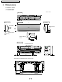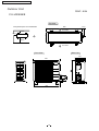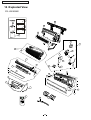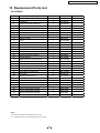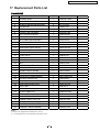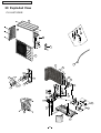
1
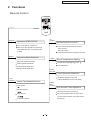
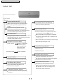
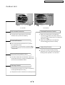
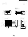
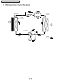
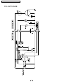
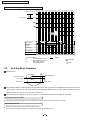
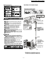
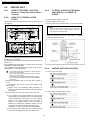
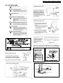
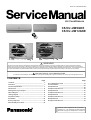
Order No. PHAAG0707018C2
Air Conditioners
CS/CU-UW9GKE
CS/CU-UW12GKE
WARNING
This serv ice informati on is design ed for experienced repair technicians only a nd is not des igned for us e by the gene ral pu blic.
It d oes no t cont ain warnings or cau tions to advise non-tech ical ind ividua ls of potenti al dangers in attempting t o serv ice a product.
Pro ducts power ed by electricity should b e serviced or repaired only by experie nced profes sional technicians. Any a ttemp t to service
or r epair the pro duct o r products dealt with in th is service informa tion by anyon e else could result in serious injury or death.
PRECAUTION OF LOW TEMPERATURE
In or der to avoid frostb ite, be assured of n o refri gerant leaka ge dur ing the insta llation or rep airing of refrigerati on circ uit.
CONTENTS
Page
-------------------------------------------------------- 2
------------------------------------------------------ 3
3 Product Specifications ------------------------------------------ 6
4 Dimensions ----------------------------------------------------- 10
5 Refrigeration Cycle Diagram ----------------------------------- 14
6 Block Diagram -------------------------------------------------- 15
7 Wiring Diagram ------------------------------------------------- 17
8 Operation Details ----------------------------------------------- 19
9 Installation
--------------------------------------------------- 29
10 2-way,3-way Valve ----------------------------------------------------- 39
11 Disassembly of The Parts -------------------------------------- 50
Page
---------------------------------------- 53
-------------------------------------------------- 55
14 Exploded View -------------------------------------------------- 58
15 Replacement Parts List ----------------------------------------- 59
16 Exploded View -------------------------------------------------- 60
17 Replacement Parts List ----------------------------------------- 61
18 Exploded View -------------------------------------------------- 62
19 Replacement Parts List ----------------------------------------- 63
20 Exploded View -------------------------------------------------- 64
21 Replacement Parts List ----------------------------------------- 65
1 Features
12 Troubleshooting Guide
2 Functions
13 Technical Data
R
C Panasonic Home Appliances Air Conditioner
(Guangzhou) Co., Ltd. (PHA-AG) All rights reserved.
Unauthorized copying and distribution is violation of
law.
CS-UW9GKE / CU-UW9GKE / CS-UW12GKE / CU-UW12GKE
1 Features
High Efficiency
Envirome ntal Fr iendly (For Refrigerant : R410A Model)
Zer o ozone depleting potential and low global
Auto Restart Control
warming potential by using R410A refr igerant.
Automatically restart after power failure
Comfort Environment
12-hour Timer Setting
Air filter with function to reduce dust and smoke
2
CS-UW9GKE / CU-UW9GKE / CS-UW12GKE / CU-UW12GKE
2 Functions
Remote Control
OFF/ON
Air
SWING
Operation START/STOP
Turn on/off the air conditi onor
Horizont al Airflow Direction Control
-Auto Con trol
When stop the operat ion by pressing
OFF /ON button,t he cursor key po ints
-Manual Control
Vertical Airfl ow Direction Manual Control
to OFF.
MODE
Airflow Direction Control
Operation Mode Selection
TEMP
Automatic Mod e Operation
Room Temperature Setting
Temperature Setti ng(16
Heating Mode Operation
to 30 )
A uto Operation
Cooling Mode Operation
Soft Dry Mode Oper ation
TIM ER
OFF/O N
Timer Operation Selection
FAN
SPEED
Stop/Start Operation Control
(set the ON/OFF Timer hourly later)
Indoor Fan Speed Selection
TIMER
SET/
CANCEL
Low Speed
Set /Cancel Timer Operation
Medium Speed
Set timer/Cancel the set timer
High Speed
By pressing SET button for 5seconds
continuously to switch to set the sensor
sensitivity.
Automatic Speed
3
CS-UW9GKE / CU-UW9GKE / CS-UW12GKE / CU-UW12GKE
Indoor Unit
N ation al
Auto Switch
Button
Power Switch ON/OFF
Anti-freezing Control for the Evaporator
When the remote control cannot be used or
for repairing and testing ,please use this
button.
Cooling or Soft Dry Operation
Signal Receiving Sound Control
Warm Booting Control
Keep pressing this button for 10seconds to turn
on or turn off the signal receiving sound.
Indoor fan starts running when temperature
of evaporator reaches 30
Auto Restart Control
or above.
When temperature of evaporator is between
Keep pressing this button for 15seconds to switch
off Auto Restart Control. To resume Auto Restart
Control,repeat the above step.
30
and 34 ,indoor fan will run at Super Low
or Low speed.
When temperature of evaporator reaches 34 ,
War m Booting Operation ends.
Operation Indication Lamps
Power (green)
Timer(orange)
Lights up in operation;
Blinks dur ing Test
Run operation and
determining Auto
Operation mode
Indoor Fan Speed Control
High,Med,Low
Auto Fan Speed
Timer in operation
Airflow Direction Control
Automatic Airflow Dir ection Control
Operation Mode
The louver automatically swings up and down
Cooling/Heating/Soft Dry /Auto Operation
Airflow Direction Manual Control
Delayed On-timer Control
Time Delay Safety Control
For cooling or soft dry mode, the unit
The unit will restart operation in 3-4
minutes after each pause.
starts 15 minutes before the set time with
the remote control, but for heating mode
30 minutes before the set time.
7-Minutes Time Save Control
7-minutes automatic restarting at Cooling
Operation
4
CS-UW9GKE / CU-UW9GKE / CS-UW12GKE / CU-UW12GKE
Outdoor Unit
CU-UW9GKE
CU-UW12GKE
Anti-reverse Protection
Overload Protection Control
To protect the compressor from reverse
rotation when power off suddenly.
When the temperature of evaporator
reaches 51 ,outdoor fan stops,and will
restart when the temperature of evaporator
declines to 49 .
When the temperature of evaporator
reaches 65 ,compressor will stop.
Overload Protector
The 2-step Overload P rotector is to protect
the compressor when
1)Temperature of compressor reaches 150
2)High temper ature or current enters into the
compressor
4-way Valve Control
If the unit is stopped dur ing H eating
O peration,the 4-way valve w ill r emain in
heating mode operation for 5 minutes.
60-seconds Test Operation Control
Once the compressor i s activated, it does not
stop for 60 seconds. It stops i mmediately with
remote control ON/OFF button.
Deicing Control
Anti-freezing operation for outdoor unit(during
Heating Mode Operation only)
Temperature of the condenser is tested by sensor.
5
CS-UW9GKE / CU-UW9GKE / CS-UW12GKE / CU-UW12GKE
3 Product Specifications
CS-UW9GKE
Unit
C U-UW9GKE
Cooling Capacity
kW
2.50
Heating Capacity
kW
2.70
Moi sture Rem oval
L /h
1.4
Power Source
Phase
V
Cycle
Single
230
50
Airflow Method
OUTLET
SIDE VIEW
TOP V IEW
INTAKE
m 3/min
7.87
-
Indoor Air (medium)
m 3/min
9.13
-
Indoor Air (high)
m 3/min
10.3
24.0
Outdoor Air
m 3/min
Air Circulation Indoor Air (low)
Input
W
Running Current
A
EER/COP
W/W
Starting Current
A
Inch
Inch
Inch
Inch
mm
m
Piping Connection Port(Flare piping)
Piping Size(Flare piping)
Inner Diameter
Length
Power Supply Cord Length
(Number of core-wire)
Drain Hose
Height
Width
Depth
Dimensions
Net Weight
Compressor
m
mm
mm
mm
kg
Type
Motor
Air Circulation
Type
Rated output
W
type
type
Input
Rated Output
Low
Fan
Med
Speed
High
-
Cooling:high48
Cooling:high39,Low31
Heating:high39,Low31
Heating:high49
Cooling:810
Heating:780
Cooling:3.80
Heating:3.70
Cooling:3.08
Heating:3.46
20
G:3-way valve3/8"
G:half union3/8"
L:2-way valve1/4"
L:half union1/4"
G:gas side3/8"
G:gas side3/8"
L:liquid side1/4"
L:liquid side1/4"
14
0.6
1.3
3 core-wire/1.0mm 2
250
530
770
650
205
230
7.5
27
Rotary(1 cylinder)
Rolling piston type
Induction(2 pole)
700
-
dB(A)
Noise Level
Electrical
Data
-
Cross-flow fan
Induction(4 pole)
13
940 60
1090 60
1230 60
Motor
W
W
rpm
rpm
rpm
6
Propeller fan
Induction(6 pole)
28
800 60
CS-UW9GKE / CU-UW9GKE / CS-UW12GKE / CU-UW12GKE
Heat
Exchanger
D escription
Tube Material
Fi n Type
Unit
CS-UW9GKE
Evaporator
Copper
Slot type
Rows/Stage
FPI
Dimensions
mm
Refrigerant Control Device
Refrigeration Oil
(c.c)
Refrigerant (R410A)
Thermostat
Protection Device
Length
C irculation
Capillary
Inner Di ameter
g
mm
L/min
mm
(Plate fin configuration,forced draft)
2 x 12
2X24
18
18
569.1X 504x36.4
610x252x25.4
540.5
C apillary Tube
R868A or FreolAlpha68M
( 320 cm3 )
800
Electronic Control
O.L.P.(230V,37A)
609 10 720 10
10.0 0.2 7.5 0.2
1.4
1.3
P.P. H oneycomb
Air Filter
Refrigerant Circulation Control Device
Compressor Capacitor
Fan Motor Capacitor
CU-U W9GK E
Condenser
C opper
Corrugation type
F, V
F, V
-
Specifications are subj ect to change without notice for further im pr ovem ent.
7
Capi llary
30 F , 370V
2.0 F , 400V
CS-UW9GKE / CU-UW9GKE / CS-UW12GKE / CU-UW12GKE
CS-UW12GKE
Unit
CU -U W12GK E
Cooling Capacity
kW
3.30
Heating Capacity
kW
3.70
Moi sture Rem oval
L /h
1.9
Power Source
Phase
V
Cycle
Single
230
50
Airflow Method
OUTLET
SIDE VIEW
TOP V IEW
INTAKE
Air Circulation Indoor Air (low)
Indoor Air (medium)
m 3/min
Indoor Air (high)
m 3/min
Outdoor Air
m 3/min
7.96
9.20
-
Input
W
Running Current
A
EER/COP
W/W
Starting Current
A
Inch
Inch
Inch
Inch
mm
m
Piping Connection Port(Flare piping)
Piping Size(Flare piping)
Inner Diameter
Length
Power Supply Cord Length
(Number of core-wire)
Drain Hose
Height
Width
Depth
Dimensions
Net Weight
Compressor
m
mm
mm
mm
kg
Type
Motor
Air Circulation
Type
Rated output
W
type
type
Input
Rated Output
Low
Fan
Med
Speed
High
31.8
-
Cooling:high39,Low32
Cooling:high49
Heating:high39,Low31
Heating:high50
Cooling:1080
Heating:1060
Cooling:5.00
Heating:4.80
Cooling:3.05
Heating:3.49
25
G:half union3/8"
G:3-way valve3/8"
L:half union1/4"
L:2-way valve1/4"
G:gas side3/8"
G:gas side3/8"
L:liquid side1/4"
L:liquid side1/4"
14
0.6
1.3
3 core-wire/1.0mm 2
280
540
799
780
183
289
9
30
Rotary(1 cylinder)
Rolling piston type
Induction(2 pole)
900
-
dB(A)
Noise Level
Electrical
Data
7.16
m 3/min
Cross-flow fan
Induction(4 pole)
18
980 60
1090 60
1260 60
Motor
W
W
rpm
rpm
rpm
8
Propeller fan
Induction(6 pole)
28
800 60
CS-UW9GKE / CU-UW9GKE / CS-UW12GKE / CU-UW12GKE
Heat
Exchanger
D escription
Tube Material
Fi n Type
Unit
CS-UW12GKE
Evaporator
Copper
Slot type
Rows/Stage
FPI
Dimensions
mm
Refrigerant Control Device
Refrigeration Oil
(c.c)
Refrigerant (R410A)
Thermostat
Protection Device
Length
C irculation
Capillary
Inner Di ameter
g
mm
L/min
mm
(Plate fin configuration,forced draft)
2 x 15
2X24
20
18
725.1
610x252x25.4
696 X504x36.4
C apillary Tube
R868A or FreolAlpha68M
( 320 cm3 )
980
Electronic Control
O.L.P.(230V,37A)
655 10 510 10
9.5 0.2 10.8 0.2
1.4
1.4
P.P. H oneycomb
Air Filter
Refrigerant Circulation Control Device
Compressor Capacitor
Fan Motor Capacitor
CU -UW12GKE
Condenser
C opper
Corrugation type
F, V
F, V
1.5 F , 400V
* 60g for air purgi ng is not included.
Specifications are subject to change without notice for further improvement.
9
Capi llary
30 F , 370V
2.0 F , 400V
CS-UW9GKE / CU-UW9GKE / CS-UW12GKE / CU-UW12GKE
4 Dimensions
Indoor Unit
CS-UW9GKE
Unit : mm
Top view
Side view
Side view
Front View
770
205
Air in take
Right Pip ing
Hole
61
49
Air ou tlet
5
Left Piping
Hole
Bottom Piping
Hole
49
61
165
Back View
Insta llation Plate Hook
56
(43)
410
79
1 6.5
Dimension of installation pla te (Front View)
(27.5)
(20)
(2 6.5)
(20)
(38 2.2)
(95.8)
(16)
(26.5)
(118.2)
4 52
10
0.5
83 .2 0 .5
CS-UW9GKE / CU-UW9GKE / CS-UW12GKE / CU-UW12GKE
Indoor Unit
CS-UW12GKE
Unit : mm
Side view
Front View
183
79 9
Air inta ke
Left Piping
Hole
Rig ht Pip ing
Ho le
Air outlet
61
165
Back V iew
Installation P late Hook
(100)
Ga s Side
Liquid
Side
(50)
(420)
56
16.5
D rain Port
Installation pla te (Fron t Vie w)
A
B
(13 1)
( 382 )
( 631 )
11
( 118)
CS-UW9GKE / CU-UW9GKE / CS-UW12GKE / CU-UW12GKE
Outdoor Unit
Unit : mm
CU-UW9GKE
Top view
61.6
650
Required space for installation
Air intake
10cm
10cm
100cm
Air outlet
Side view
Front View
250
230
668
55.8
61.6
88
88
650
12
293
CS-UW9GKE / CU-UW9GKE / CS-UW12GKE / CU-UW12GKE
Outdoor Unit
CU-UW12GKE
Unit : mm
Top view
More
than 10cm
105
7 80
5 70
48
More
than 10cm
More than 100 cm
Side view
Front View
274
16
320
352
13
CS-UW9GKE / CU-UW9GKE / CS-UW12GKE / CU-UW12GKE
5 Refrigeration Cycle Diagram
INTAK E AI R
SE NSOR
PIPI NG
SENSOR
PIPIN G
SENSOR
4 -wa y va lve
Cool ing
Heating
14
CS-UW9GKE / CU-UW9GKE / CS-UW12GKE / CU-UW12GKE
6 Block Diagram
CS-UW9GKE/CU-UW9GKE
SSR201
15
CS-UW9GKE / CU-UW9GKE / CS-UW12GKE / CU-UW12GKE
CS-UW12GKE
SSR201
16
CS-UW9GKE / CU-UW9GKE / CS-UW12GKE / CU-UW12GKE
7 Wiring Diagram
CS/CU-UW9GKE
WIRELESS REMOTE
CONTROL
W
1
RECEIVE R
COMPLETE
ELECTRONIC CONTROLLER
1
1
W
3
CN-STM
3
W
W
W
W
W
W
W
W
W
W
1
AU TO SWIT CH
SW 101
10
1
O
Y
5
IN DICATOR
COMPL ETE
BR
R
W
5
P
STEPPING
MOTO R
1
CN-FM
C-FM
1
B
3
R
5
Y
10
FAN MO TOR
P
BR
C 17
3
FUSE
T3 15A L250V
BL
L
Y/G
4
3
L1
C N-FB
1
T01
4
ACW HT
CN-TH
Cr201
W
B
SENSOR(PIPING TEMP.)
3
2
SENSOR(INTAKE TEM P.)
RY-HOT
FM(BLU)
BL
1
THERMAL FUSE
HOT(RED)
R
W
BR
S SR 202
HA
1T
1
2
3
4
Y/G
IND OO R U NIT
TE RM INAL BOARD
1(L)
2(N)
3
4
102
O UTD OOR UNIT
TE RM INAL BOARD
1(L)
Y
2(N)
3
FUSE
250V 3A
4
Y
W
R : RED
BL : BLACK
B : BLUE
BR : BROWN
O : OR ANGE
YELLOW
C
1
OLP
(37A 230V)
R
3
Y
S
BLUE
FAN MOTOR
RED
TRADE MARK
CO MPRESSOR
B
R
R
B
CAPACITOR
Y-B M
Y-R A
COMPRESSOR TERMINAL
80
70
B
OUTDOOR UNIT
60
50
)
CS-UW9GKE
CWA921372
397
40
30
308.1
OUTDOOR FAN MOTOR RESISTANCE( )
20
CU-UW9GKE
CONNECTING CWA951427
10
Y-B
275
Y-R
260
Sensor ( Thermistor ) characteristics
C APACITOR
IND OOR FAN MOTOR RESISTANCE(
CONNECTING
GRY : GREY
G : GREEN
Y : YELLOW
W : WHITE
Y/G : YELLOW/GREEN
0
-10
0
10
20
Temperature (
R emark:
17
30
40
50
)
:Outdoor Pi pe Temp. Sensor
:I ndoor intake/ Outdoor ai r sensor
: Indoor pipe Temp. Sens or
CS-UW9GKE / CU-UW9GKE / CS-UW12GKE / CU-UW12GKE
CS/CU-UW12GKE
WIRELESS REMOTE
CONT ROL
IN DICATOR
COMPL ETE
S W101
ELECTRONIC CONTROLLER
W
W
W
W
W
W
W
W
W
W
W
1
11
BR
1
R
1
1
O
CN-STM
Y
5
P
5
STEPPING
MOTOR
C N-FM
11
C-FM
1
B
3
R
5
Y
FAN MO TOR
P
BR
C
P3
3
FUSE
L
Y/G
1
T
T 3 15A L 250 V
BL
W
BR
L01
BL
SENSOR (PIPING TEMP.)
L4
1
ACWHT
3
Cr
W
R
HOT(RED)
B
FM(BLU)
RY-HOT
SS R202
L
VEN TILATOR
IN TERLOCKING
UNIT
OPTIONAL
C
AUTO SW
1T
Y/G
IND OO R U NI T
TERM INAL BOARD
1(L)
2(N)
3
4
INDOOR UNIT
FUSE
250V 3A
250V 3A
T HERMA L FUS E
102
O UTDOOR UNIT
TERM INAL BOARD
1(L)
2(N)
3
102
4
YELLOW
C
R : RED
BL : BLACK
B : BLUE
BR : BROWN
O : ORANGE
Y
W
R
S
BLUE
RED
FAN MOTOR
Y
TRADE MARK
CO MPRESSO R
COMPRESSOR TERM INAL
B
R
R
GRY : GREY
G : GREEN
Y : YELLOW
W : WHITE
Y/G : YELLOW/GREEN
B
CAPACITOR
CAPACITOR
B
80
OUTDOOR UNIT
Sensor ( Thermistor ) characteristics
70
INDOOR FAN MOTOR RESISTANCE(
60
)
50
CS-UW12GKE
CONNECTING CWA921378
Y-B
Y-R
M
A
40
419.8
304.4
30
OUTDOOR FAN MOTOR RESISTANCE(
20
)
CU-UW12GKE
10
CONNECTING CWA951427
275
Y-B
Y-R
260
0
-10
0
10
20
30
40
50
Temperature ( )
R emark:
18
:Outdoor Pi pe Temp. Sensor
:I ndoor intake/ Outdoor ai r sensor
: Indoor pipe Temp. Sensor
CS-UW9GKE / CU-UW9GKE / CS-UW12GKE / CU-UW12GKE
8 Operation Details
8.1 Cooling Mode Operation.
When selecting the Cooling Mode Operation, the unit will operate according to the setting by the Remote Controller or
the control panel on the indoor unit and the operation is as the following.
Time Delay Safety Control
3 min.----If the compressor stops, it will not restart within 3 minutes.(Protection of compressor).
7 Minutes Time Save Control
7 min.----The unit will automatically operate in 7 minutes even if the room temperature is not reached.
(Prevention of raising the humidity)
Evaporator
Temperature
Anti-Freezing Control
(
If temperature of evaporator is lower than 2 continuously
for 4 minutes, the compressor will cease to pr event the
evaporator from freezing. Fan speed setting will not be
changed.
When temperature of evaporator reaches 10 ,compr essor
will restart.
)
Restart
10
4 minutes
2
C ompressor cease s
During Cooling Mode Operation, the Time Delay Safety
Control is available.
Time
Automatic Fan Speed Mode
During Cooling Mode Operation, use remote controller to select Automatic Fan Speed.
Fan speed will be at the point between "High speed" and "Medium speed".
Deodorization control.
2
1
Slow
Slow
Slow
Slow
Indoor Fan
STOP
40
Compressor
30
20
STOP
STOP
16 0
40
STOP
ON
1 Fan speed will be at Hi till the compressor ceases (set temperature reached).
2 Fan speed will be at Me when the compressor restarts.
19
30
ON
CS-UW9GKE / CU-UW9GKE / CS-UW12GKE / CU-UW12GKE
Time Graph for Cooling Operation
Intake air te mperature
a b c d e f g h i j k l mn o p q r s t u v w x y z
Start
1.5
Set temp erature
Stop
31
29
10
Evaporater
temperature
Basic Time
1
1
3
7
2
1
4
3
Comp.
Indoor Fan
Outdoor Fan
Operation Indicator
Operation status
:
Time delay safety control
:
Compressor Test control
:
Auto restart control
:
Anti-freezing Control
d-g
g-h
h-o
q-t
8.2.
Time
Operate
Stop
Soft Dry Mode Operation
Operation area
COO LING
COOLING(OFF)
COOLING(ON)
1 .5
DRY(ON)
DRY
DRY(OFF)
1 .0
DRY(ON)
DRY(OFF)
When selecting Soft Dry mode operation, the operation will be cooling until the room temperature reaches the set temp on
remote control, and then Soft Dry will be activated. (During Soft Dry Mode the fan of indoor unit will operate at super low
speed. The soft dry mode will run for less than 10 minutes.)
Once Soft Dry mode operation is turned off, indoor fan, compressor and outdoor fan will stop for 6 minutes.
Time Delay Safety Protection
During cooling mode operation, if the compressor ceased, it will not restart within 3 minutes.
Anti Freezing Control
Same as the denotation in Cooling Operation.( P19 )
(During Soft Dry Mode Operation, compressor will stop for at least 6 min.)
20
CS-UW9GKE / CU-UW9GKE / CS-UW12GKE / CU-UW12GKE
Automatic Fan Speed
During Soft Dry Operation, use re mote controller to select Auto F an Speed mode.
Indoor Fan Speed is at L oLo-
LoS lo
Slo
Ind oor
fan
OFF
Slo
OFF
OFF
T1
40
6
T2
T2
70
70
10
10
ON
Compressor
OFF
T1
40
ON
OFF
Time Graph for soft dry operation
a b c d e f
g
h i
j
k l m n o p q
r s t
Intake Air temp
Cooling mode operation activated
1.5
1.0
Cooling mode operation stopped
Soft mode operation activated
Soft dry mode operation stop
o
Evaporator
temperature
10 C
o
2C
1
Basic Time
6
6
1
1
6
4
6
Comp.
Super
Slo Slo
Indoor Fan
Slo
Low
Super
Slo
Low
Low
Slo Slo
Slo Slo
Slo
Slo
Slo
Outdoor Fan
Operation Indicator
4-way Valve
Time
Operation status
a-c,p-r
:
c- p ,r - u
:
:
e-f
j-l
q-t
:
:
Cooling Mode Operation
Soft Dry Mode Operation
Soft Dry Mode Operation Stopped
Compressor Test Operation Control
Anti Freezing Control
21
Operate
Stop
u
CS-UW9GKE / CU-UW9GKE / CS-UW12GKE / CU-UW12GKE
8.3.
Heating Mode Operation
When selecting the Heating Mode Operation, the unit will operate according to the setting by the Remote Controller and
the operation is as the following.
Time Delay Safety Control
If the compressor stopped by switching off, turning off by remote controller, or power off, it will not restart within 3 minutes.
When room temperature reaches the set temperature on the remote controller, compressor stops and will not restart within
4 minutes.
3 minutes after the compressor stopped, indoor fan will stop for 1 minute. Then indoor fan will resume operation with the
speed at super low
.
Over Load protection Control
When temperature of indoor heat exchanger rises to 51 , outdoor fan will stop
when temperature of indoor heat exchanger falls to 49 , outdoor fan will restart.
When temperature of i ndoor heat exchanger rises to 65
Indoor Heat Exchanger
or above, compresso r stops, and wi ll restart 4 minute s l at er.
Compressor
Compressor Restarts
Stops
4 minutes later
65
Anti-reversing Control
If the compressor has been continuously running for 5 minutes or longer, and the difference of temperature between
intake air and evaporator is continuously lower than 5.0 or below for 2 minutes, the compressor will stop , and then
restart 3 minutes later.(Time Delay Protection Control is effective.)
Compressor runs
T
5
5 min
Compressor
Compressor Restarts
Stops
3 minutes later
last for 2 min
T= intake air temperature - evaporator temperature
4-way valve control
During heating mode operation,4-way valve is at open mode.
During heating mode operation,if the unit turned off, the 4-way valve will remain
at open mode for 5 minutes.
Warm Booting Control
When turning on the unit by heatin g mode operation,indoor fan
will be activated when temperatur e of indoor heat exchanger
reaches 30 . (See the figure on the right)
Warm boot operation ends when t emperature of indoor heat
exchanger reaches 34 .
22
CS-UW9GKE / CU-UW9GKE / CS-UW12GKE / CU-UW12GKE
Automatic Fan Speed
During Heating Operati on, u se remote controller to select Auto Fan Speed mode.
Indoor Fan Speed i s between Me and Slo .
Manual fan speed
Time Graph for Heating Operation
42
a b c d e f g h i j k l m n o p q r
Blink
Operate
34
Indoor heat
exchanget
Temp.
Stop
32
30
OFF
Intake Temp.
2
ON
2'58''
Basic Time
30'
1'
30
150'
Compressor
Indoor Fan
Outdoor Fan
Operati on I ndicat or
SL O SL O LO -
SS LO SS LO
4-way valve
<Operation status>
a-b
: Warm booting control(indoor fan Off)
c-d
: Warm booting control(indoor fan Super Slo)
h - k , o - r : Prevent cool air blowing out
23
SS LO SS L O
CS-UW9GKE / CU-UW9GKE / CS-UW12GKE / CU-UW12GKE
Deice Control
Deice operation is to protect the outdoor unit from freezing.
Normal Deice Operation
Deicing starts 30 minutes after heating mode operation or 60 minutes after the latest deicing operation. If temperature of
outdoor piping, tested by TRS, falls to -3 (TRS OFF) or below for continuously 50 seconds, deicing operation starts.
Overload Deicing Operation
During heating operation, if the accumulative stopping time of outdoor fan reaches 60 minutes,
deicing operation will start 1 minute after compressor starts.
Deicing operation ends under conditions below
(a) After 12 minutes.
(b) Temperature of outdoor unit rises to 4 .
(c) As the illustration showed bellow and due to Time Delay (Td), deicing won t ends immediately.
Once deicing operation starts, it won t end until 60 seconds later.
When deicing operation ends, compressor will stop for 30 seconds, and 4-way valve remains at cooling mode operation
for 10 seconds.
Time Graph for Normal Deicing Operation
42
a b c d e f g h i
j k l m n o p q r s t u v w x y z
34
30
m ax60'
max60'
6 0'
ma x12'
ma x12'
Ba sic Time
20S 20S
Co mpressor
Indo or F an
Ou tdoor F an
Op era tion L ED
4 -way valve
a- c
c- g
h-j, u- w
o -r
10S 2 0S
20S 20S
Slo Lo
Td 10S 20S
Slo L o
D eici ng c onf irm a ti on
D eici ng o per at ion( ti me r es et)
Wa rm Bo otin g
De ic ing( TRS )
24
or
CS-UW9GKE / CU-UW9GKE / CS-UW12GKE / CU-UW12GKE
Time Graph for Overload Deicing
a b c d e f g h i j k l m n o p q
51
49
Basic time
Out door f an stop for 6 0' acc umulatively 20
Compressor
Indoor fan
Outdoor fan
Operation Indicator
4-way valve
<Operation status>
a-i Overload control
i-l
Overload deicing(timer)
l-m: Warm booting control
m-r Overload control
25
20
Max
12 10
20
6 0'
CS-UW9GKE / CU-UW9GKE / CS-UW12GKE / CU-UW12GKE
8.4.
Automatic Mode Operation
Standard for Determining Operation Mode
First Determination:
Intake Air
temperature
23
Setting Temperature (Standard)
Cooling mode
Cooling mode
Soft Dry mode
20
Heating mode
Soft Dry mode
25
22
Heating mode
21
Second Determination:
One hour after the above determination, the unit will operate according to the table below.
Second Determi nation
Cooling
C ooling
First
determination
23
D ry
or above
20
Dry
25
H eating
or above
or above
H eating
23
below
20
below
25
below
A) Indoor fan operates at super low speed for 25 seconds.
B) After judging indoor air temperature, the operation is determined and operation continued at the mode determined.
C) If indoor temperature is less than 16 , heating operation will immediately operate.
D) After the operation mode has been determined, the mode does not change. However,Soft Dry mode operation
includes cooling mode operation.
E) If automatic mode operation is started while the unit is operating,operation will continue.
If current operation is in cooling mode (including the cooling mode operation when is a part of Soft Dry mode
operation) it will be maintained, and if current operation is not cooling mode, the appropriate operation mode is
determined for 25seconds at super slow fan speed.Then the selected mode will continue.
F) Room temperature adjustment
Higher
2
Standard
0
Low er
2
26
CS-UW9GKE / CU-UW9GKE / CS-UW12GKE / CU-UW12GKE
8.5 About Cursor Key Which Points To
OFF On Remote Control
W hen the ON/OFF button on th e remot e contro l is pressed, the cursor key which points to OFF will appear or
disappear to in dicate t he ON/OFF status of the air cond itioner.
AUTO
HEAT
COOL
DRY
OFF
AUTO
AUTO
FAN
SPEED
AIR
SW ING
PRESS "OFF/ON" BUTTON
AUTO
HEAT
COOL
DRY
OFF
AUTO
AUTO
FAN
SPEED
AIR
SW ING
For some reason (Ex. The sign al of the rem ote cont rol does not reach the sig nal rece iver of t he indoor unit.), the
display of the remote control w ill not correspond wit h the actual ON/OFF stat us of the indoor unit:
1. Th e air co nditi one r is running but the curso r key wh ich points to OFF appears. The air con ditioner can be
stopped w ith any button (Excep t for ON /OF F , TIMER SET , TI MER ON ) press ed.
2. Th e air conditioner is on standby, but the cursor key which points to OFF disapp ears. The air con ditioner can
be started with any butt on(Except for O N/O FF , TIMER SET , TIMER O FF ) pressed.
8.6.
Indoor Fan Motor Control
Automatic fan speed control
When automatic fan speed set, the available range for fan speed is from Hi to Slo.
Manual Fan Speed Control
Basic fan speed can be manually adjusted (Lo, Med, Hi) by using the fan speed selection button.
Basic Fan Speed
Category
Hi
Me
Lo
Lo-
SLo
SSLo
Cooling Mode Manual
Operation
Auto
Soft Dry
Operation
Manual
Auto
Manual
Heating Mode
Operation
Auto
8.7
Auto restart control
If the operation is stopped due to a power failure u nder any operation mode, it wil l r estart automat ical ly
under the previous operation mode when the power supply i s resumed.
27
CS-UW9GKE / CU-UW9GKE / CS-UW12GKE / CU-UW12GKE
8.8
Airflow Direction Control
Airflow Direction Auto-control
When set at airflow direction auto-control with remote control,the louver swings up and down as shown in the table below.
The louver does not swing when the indoor fan stops during operation.
When stop the unit with remote control,the discharge vent is closed with the louver.
When temperature of indoor heat exchanger reaches 38
during heating mode operation, if temperature falls to 35 ,airflow
direction will change from the lower limit to horizontal.
The left and right airflow direct ion l ouver can be adj usted manually.
Airflow direction manual control
When t he airflow directi on set button is pressed,t he a utomatic airflow is released and t he
airflow direction louver moves up and down as show n in t hetable below. The louver can
be stopped by releasing the button at the desired position.
When t he remote co ntrol is used to stop the operation,the discharge v ent i s closed with
airflow direction lou ver.
Angles Of Airflow Direction Louver
1
2
3
4
5
o
32
Operating Mode
Cooling
Soft dry
Manual
o
12
o
26
Auto
o
12 ~36
Manua
Heating
17
o
9
o
29
44
o
9 ~55
Auto
Determining operation
mode
36
o
o
o
21
o
o
o
55
o
o
9
N otes:
In heating mode operation
1. Airflow direction automatic control:
Airflow direction is automatically adjusted to horizontal direction when the temperature of indoor heat exchanger is low and it will
be automatically adjusted downward while the indoor temperature rises.
2. Airflow direction manual control:
The airflow direction is automatically adjusted to horizontal direction when temperature of indoor heat exchanger is low .While
temperature of indoor heat temperature rises ,the airflow direction is automatically adjusted to the place set by the remote control.
In cooling or soft dry mode op eration
If the compressor continues to operate for 60 minutes ,and the louver direction is at No 5,the fan speed is below Med, the intake
air temperature is below 29
and continues to change between 2
to prevent dew around the discharge vent.
28
for 30 minutes ,the louver direction will be at No 2 in order
U
El
C
10.
.
U
U
U
U
U
U
U
U
U
U
U
U
U
CS-UW9GKE / CU-UW9GKE / CS-UW12GKE / CU-UW12GKE
9.2.
INDOOR UNIT
9.2.1.
SELECT THE BEST LOCATION
(Refer to "Select the best location"
section)
9.2.2.
HOW TO FIX INSTALLATION
PLATE
9.2.3.
1. Insert the piping sleeve to the hole.
2. Fix the bushing to the sleeve.
The mounting wall is strong and solid enough to prevent it from
the vibration.
Wall
more than 450mm
more than 450mm
TO DRILL A HOLE IN THE WALL
AND INSTALL A SLEEVE OF
PIPING
3. Cut the sleeve until it extrudes about 15 mm from the wall.
Wall
Caution
When the wall is hollow, please be sure to use the
sleeve for tube ass•y to prevent dangers caused by
mice biting the connecting cable.
Screw 2
165mm
( E )
105mm
Installation
plate 1
A
225mm
4. Finish by sealing the sleeve with putty or caulking
compound at the final stage.
145mm
C
B
B
(For Models:CS-UW9GKE)
More than 450 mm
É¿´´
More than 450 mm
É¿´´
Í ½®»© 2
( B )
ײ- ¬¿´´¿¬·±²
°´¿¬» 1
Ó»¿- «®·²¹ ¬¿ °»
î îì ³³
A
ïîë ³³
îïç ³³
ï ëð ³³
(For Models:CS-UW12GKE)
The centre of installation plate should be at more than 450 mm
at right and left of the wall.
The distance from installation plate edge to ceiling should more
than 67 mm.
From installation plate left edge to unit's left side is 62 mm(CSUW9GKE) or 98(CS-UW12GKE).
From installation plate right edge to unit's right is 79 mm (CSUW12GKE) or 112 (CS-UW12GKE).
9.2.4.
INDOOR UNIT INSTALLATION
1. For the right rear piping
: For left side piping, piping connection for liquid should be
about 10 mm from this line.
: For left side piping, piping connection for gas should be
about 45 mm from this line.
: For left side piping, piping connecting cable should be
about 785mm (CS-UW9GKE) or 800mm (CS-UW12GKE)
from this line.
1. Mount the installation plate on the wall with 5 screws or
more.
(If mounting the unit on the concrete wall consider using
anchor bolts.)
Always mount the installation plate horizontally by
aligning the marking-off line with the thread and using a
level gauge.
•
2. Drill the piping plate hole with ø70 mm hole-core drill.
according to the arrows marked on the lower left
• Line
and right side of the installation plate. The meeting point
of the extended line is the centre of the hole. Another
method is by putting measuring tape at position as
shown in the diagram above. The hole centre is
obtained by measuring the distance namely 105 mm
and 145mm for left and right hole respectively (CSUW9GKE), or 150mm and 125mm for CS-UW12GKE.
the piping hole at either the right or the left and the
• Drill
hole should be slightly slanted to the outdoor side.
- 32 -
2. For the right and right bottom piping
U
U
Make sure do not fasten and collect the power supply cord into the piping
trough, otherwise, it will cause heat or fire. The power supply cord must not
be stucked at the 2 clip-on positions and overly exposed between the mounting
plate and the indoor unit. Abnormal noise may be produced.
Sleeve for
piping hole
Drain
hose
Connecting cable
Piping
- 33 -
More than approx. 95 cm
U
U
U
U
U
U
5
4-
U
9.3.
HOW TO TAKE OUT FRONT GRILLE
Please follow the steps below to take out front grille if
necessary such as when servicing.
U
U
OUTDOOR UNIT
9.3.1.
SELECT THE BEST LOCATI ON
(Refer to "Select the best location
section")
9.3.2.
INSTALL THE OUTDOOR UNIT
1. Set the vertical airflow direction louver to the horizontal
position.
2. Slide down the two caps on the front grille as shown in the
illustration at right, and then remove the two mounting
screws.
U
After selecting the best location, start installation according
to Indoor/Outdoor Unit Installation Diagram.
3. Pull the lower section of the front grille towards you to
remove the front grille.
1. Fix the unit on concrete or rigid frame firmly and horizontally
by bolt nut. (ø10 mm).
When reinstalling the front grille, first set the vertical
airflow direction louvre to the horizontal position and
then carry out above steps 2 - 3 in the reverse order.
2. When installing at roof, please consider strong wind and
earthquake. Please fasten the installation stand firmly with
bolt or nails.
B
Unit: mm
C
A
Model
B
C
D
474
87
20
261
CU-UW12GKE
570 103.9 19.5 320
D
A
CU-UW9GKE
AUTO SWITCH OPERATION
9.3.3.
The below operations will be performed by pressing the
• AUTO switch.
CONNECTING THE PIPING
Connecting The Piping To Indoor Unit
Please make flare after inserting flare nut (locate at joint portion
of tube assembly) onto the copper pipe. (In case of using long
piping)
1. AUTO OPERATION MODE
The Auto operation will be activated immediately once the
Auto Switch is pressed.
Connect the piping
2. TEST RUN OPERATION (FOR PUMP DOWN/SERVICING
PURPOSE)
Align the center of piping and sufficiently tighten the flare
nut with fingers.
The Test Run operation will be activated if the Auto Switch
is pressed continuously for more than 5 sec. to below 10
sec. A "Pep" sound will occur at the fifth sec., in order to
identify the starting of Test Run operation
Further tighten the flare nut with torque wrench in specified
torque as stated in the table.
3. REMOTE CONTROLLER RECEIVING SOUND ON/OFF
The ON/OFF of Remote Controller receiving sound can be
changed over by pressing the "AUTO" Switch continuously
for 10 sec. and above. A "Pep" "PeP" sound will occur at the
tenth sec., in order to indicate the "ON/OFF" changed over
of remote control receiving sound.
Piping size (Torque)
Gas
Liquid
3/8'' (42 N.m)
1/4'' (18 N.m)
Connecting The Piping To Outdoor Unit
CS-UW9GKE
Decide piping length and then cut by using pipe cutter. Remove
burrs from cut edge. Make flare after inserting the flare nut
(located at valve) onto the copper pipe.
CS-UW12GKE
Align center of piping to valves and then tighten with torque
wrench to the specified torque as stated in the table.
35
U
U
U
U
U
U
U
U
G
U
U
G
U
U
U
U
CS-UW9GKE / CU-UW9GKE / CS-UW12GKE / CU-UW12GKE
10
Installation and Serving Air Conditioner Using R410A
10.1. OUTLINE
10.1.1
About R410A Refrigerant
1. Converting air conditioners to R410A
Since it was declared in1974 that chlorofluorocarbons (CFC), hydro chlorofluorocarbons (HCFC) and other substances pose
a destructive danger to the ozone layer in the earth s upper stratosphere (20 to 40 km above the earth), measures have been
taken around the world to prevent this destruction.
The R22 refrigerant which has conventionally been used in ACs is an HCFC refrigerant and, therefore, possesses this ozone
destroying potential. International regulations (the Montreal Protocol Ozone-Damaging Substances) and the domestic laws of
various countries call for the early substitution of R22 by a refrigerant which will not harm the ozone layer.
In ACs, the HFC refrigerant which has become the mainstream alternative called R410A. Compared with R22, the
pressure of R410A is approximately 1.6 times as high at the same refrigerant temperature, but the energy
efficiency is about the same. Consisting of hydrogen (H), fluorine (F) and carbon (C), R410A is an HFC
refrigerant. Another typical HFC refrigerant is R407C. While the energy efficiency of R407C is some what inferior
to that of R410A, it offers the advantage of having pressure characteristics which are about the same as those of
R22, and is used mainly in packaged Acs.
2. The characteristics of HFC (R410A) refrigerants
a. Chemical characteristics
The c hemical charact erist ics o f R4 10A are similar t o those of R22 in that both are che mically stable, nonflamm abl e ref rigerant s wit h low toxicity.
Howe ver, just like R22 , the specifi c gra vity of R410A gas is heavier t han that of air. Becau se o f thi s, it can caus e
an oxygen deficiency if it l eaks into a closed room since it collects in the lowe r area of the room. It also gen erates
toxic gas when it i sdire ctly exposed to a flame, so it must be used in a well ventila ted envi ronm ent whe re i t will
not collec t.
Table 1 Physi cal comp arison o f R4 10A and R22
Composition (wt%)
R410A
R22
R32/R125(50/50)
R22(100)
-51.4
-40.8
1.56 Mpa(15.9 kgf/cm2)
0.94 Mpa(9.6 kgf/cm2)
64.0 kg/m3
44.4 kg/m3
Non-flammable
Non-flammable
0
0.005
1730
1700
Boiling point ( C)
Vapori zing p ressur e (25 C)
Satura ted va por de nsity
Flamm ability
Ozone -destr oying point ( ODP)
Globa l-warm ing po int (GWP)
b. Comp osi tional change (pseudo-azeotropic charact eristics)
R41 0A is a pseu do-azeo trop ic m ixture comprising the two com ponents R32 and R1 25. Mult i-compo nen t
refr iger ants with the se c hem ical cha racterist ics e xhibit lit tle c omp ositi ona l change even fro m phase cha nge s
due to v apo riza tion 9or cond ens ation), w hich mea ns t hat there is l ittle chan ge in the cir cula ting refri gera nt
com pos ition eve n w hen the refrigera nt le aks from the gaseous sec tion of th e piping .
Acc ordi ngly, R4 10A can be handled i n almost the sam e manne r as the sing le-c omp one nt re frigeran t R2 2.
How eve r, w hen charging, be cau se there is a slight change in c omp osit ion betw een the gas pha se a nd th e liquid
pha se i nsid e a c ylin der or ot her containe r, ch argi ng s houl d basically begin with the liqu id si de.
c. Press ure characterist ics
As seen in Table 2, t he gas pressure of R410A is a pproxim atel y 1.6 tim es a s high as tha t of R22 at the same
refr iger ant t emp erat ure, whi ch m ean s that special R410A tool s and ma teri als w ith h igh-pressur e sp ecifi cati ons
mu st be use d fo r all refri gera nt p iping wo rk and servicing.
Table 2 Comparison of R410A and R22 saturated vapor density
Refrigerant Temperature( C )
R410A
R22
-20
0.30
0.14
0
0.70
0.40
20
1.35
0.81
40
2.30
1.42
60
3.73
2.33
65
4.15
2.60
39
U
U
U
U
d. R410A refrigerating machine oil
Conventionally, mineral oil or a syntheti c oil suc h as alkylbenzen e has been used for R22 refrigerating ma chin e
oil . Becaus e of the poo r compatibili ty betwe en R410 A and conve ntional oils l ike mineral oil, however, ther e is a
tenden cy f or the refrigerat ing machine oil to collect in the refri gera ting cycle. For t his reas on, poly este r an d
other synth etic oils which have a hig h co mpa tibil ity w ith R410 A are us ed as re frigerating m ach ine oil.
Because of the hig h hygro scop ic p roperty of synthetic oil, more ca re must be t aken in its handling tha n was
necess ary with conventional refrig erat ing mac hine oils . Al so, t hese sy nthe tic oils will degrade if mixed wi th
mi neral oil or alkyl ben zene , ca usin g cl oggi ng i n capillary t ubes or com pres sor mal func tion . Do not mix the m
under any circu mst ances.
10.1.2
Safety Measure When Installing / Receiving Refrigerant Piping
Cause the gas pressure of R4 10A is a pproxim ately 1.6 tim es as hi gh as that o f R22, a mistake in installat ion or
servici ng could result in a maj or accident. It is es sent ial t hat you use R410a tool s an d materials, and that you
observe the fol lowi ng preca utions to ensure safety.
1. Do not u se any refrigerant other than R410A in Acs that have been used with R410A .
2. If any refrigerant gas leaks while you are working, ventilate the room. Toxic gas may be generated if r efrigerant
gas is exposed to a direct flame.
3. When instal ling or transferring an AC, do not allow any air or sub stance other than R410A to mix into the
refri geration cycle. I f it doe s, the p ressure in the r efrigeration cycle can become abnormally high, possibly
causing an explosion and/or injury.
4. Afte r finishing the installation, check t o make sure there is no refrigerant gas leaking.
5. When install ing or transf erring an AC, follow the instruct ions in the i nsta llation instructions caref ully. Incorrect
installation can resul t in an abnormal refri geration cycl e or wat er leakage, elect ric s hock, fire, et c.
6. Do not perform any alterations on the AC unit under any ci rcumstances. Have all repair work done by a specialist.
Incorrect repairs can result in an water leakage, el ectric shock, fire, etc.
10.2.
TOOL FOR INSTALLING / SERVICING REFRIGERANT PIPING
10.2.1
Necessary Tools
In ord er to pre ven t an R41 0A A C from mistaken ly being charged with any other re frige ran t, the dia met er of the 3-w ay
v alve serv ice port on t he o utdo or u nit h as b een cha nged . Als o, t o inc reas e its abi lity t o wi thsta nd p res sure , the
o ppo sing dim ensi ons have been changed f or the refrigerant pipe flaring size and flare nu t. Ac cord ingl y, wh en
in stal ling or s ervic ing refri gera nt p iping, yo u must have both the R41 0A a nd o rdin ary tool s list ed b elow.
Table 3 Tools for installation, transferring or replacement
Type of work
Flaring
Bending, connecting pipes
Ordinary tools
R410A tools
Fl aring t ool (cl utch ty pe), p ipe cut ter, re amer
To rque wrenc h (no minal diam eter 1/4,
3/ 8,1/2) Fixed spann er (op posin g side s 12
m m, 17 mm, 19 mm ) Adj ustabl e wre nch,
Sp ring b ender
Air purging
Va cuum pump Hexag onal wrench
(o pposin g side s 4 mm )
Gas leak inspection
Ga s leak inspec tion fl uid or soapy water
Cop per pip e gau ge for cleara nce
Adju stmen t, flari ng too l (clutc h type )*1)
Mani fold ga uge, c hargin g hos e, vac uum
pump adap tor
Electric gas leak detector for HFC
refrigera nt*2)
*1 ) Yo u ca n use th e co nventional (R 22) flaring t ool. If you ne ed t o buy a n ew t ool, buy the R41 0A type.
*2 ) Us e w hen it is necessa ry to det ect smal l gas lea ks.
*F or o the r ins talla tion wor k, yo u sh ould have th e usual t ools, su ch as screwdrivers (+ ,-), a me tal-c uttin g sa w, a n
e lectr ical drill , a h ole c ore drill (65 or 70 dia .), a tape measu re, a leve l, a thermom eter, a c lam p me ter, an in sula tion
te ster, a v oltm eter, etc .
Table 4 Tool for serving
Type of work
Ordinary tools
Refrigerant charging
Brazing (Replacing refrigerating
cycle part*1)
R410A tools
Elec tronic scale for refrigerant char ging
Refr igeran t cylin der Charging orific e and
packing fo r refrig erant cylinder
Nitr ogen blow s et (be sure to use n itroge n
blo wing fo r all b razing ), and brazin g), an d
bra zing m achin e
*1 ) Al way s rep lace the dry er of the outdoor unit at the same time. The rep lace me nt dr yer i s wr app ed in a vacuum
p ack. Rep lace it la st a mon g th e ref rige rating cycle parts. St art brazin g as soo n as you have opene d th e va cuu m pa ck,
a nd b egin the vac uum ing
40
U
10.2.2.
U
U
U
R410A Tools
1. Cooper tube gauge for clearance adjustment
(used when flaring with the conventional flaring tool (clutch
type))
This gauge makes it easy to set the clearance for the
copper tube to 1.0-1.5 mm from the clamp bar of the
flaring tool.
Fig. 1 Copper tube gauge for clearance adjustment
2. Flaring tool (clutch type)
In the R410A flaring tool, the receiving hole for the
clamp bar is enlarged so the clearance from the clamp
bar can be set to 0-0.5 mm, and the spring inside the
tool is strengthened to increase the strength of the pipeexpanding torque. This flaring tools can also be used
with R22 piping, so we recommend that you select it if
you are buying a new flaring tool.
Fig. 2 Flaring tool (clutch type)
3. Torque wrenches
Fig. 3 Torque wrenches
For 1/4 (opposite side x torque)
For 3/8 (opposite side x torque)
For 1/2 (opposite side x torque)
Table 5
Conventional wrenches
17 mm x 18 N.m (180 kgf.cm)
22 mm x 42 N.m (420 kgf.cm)
24 mm x 55 N.m (550 kgf.cm)
R410A wrenches
17 mm x 18 N.m (180 kgf.cm)
22 mm x 42 N.m (420 kgf.cm)
26 mm x 55 N.m (550 kgf.cm)
4. Manifold gauge
Because the pressure is higher for the R410A type, the conventional type cannot be used.
Table 6 Difference between R410A and conventional high / low-pressure gauges
Conventional Gauges
R410A Gauges
High-pressure gauge (red)
-76 cmHg - 35 kgf/cm3
-0.1 - 5.3 Mpa -76 cmHg - 53 kgf/cm 3
High-pressure gauge (blue)
-76 cmHg - 17 kgf/cm3
-0.1 - 3.8 Mpa -76 cmHg - 38 kgf/cm 3
The shape of the manifold ports has been changed to prevent the possibility of mistakenly charging with another type of
refrigerant.
Port size
Table 7 Difference between R410A and conventional manifold port size
Conventional gauges
R410A gauges
7/6 UNF 20 threads
1/2 UNF 20 threads
- 41 -
U
U
U
U
5. Charging hose
The pressure resistance of the charging hose has been
raised to match the higher pressure of R410A. The hose
material has also been changed to suit HFC use, and
the size of the fitting has been changed to match the
manifold ports.
Fig. 4 Manifold gauge charging hose
Pressure
resistance
Material
Table 8 Difference between R410A and conventional charging hoses
Conventional hoses
R410A hoses
Working pressure
3.4 MPa (35 kgf/cm3)
5.1 MPa (52 kgf/cm 3)
Bursting pressure
17.2 MPa (175 kgf/cm3)
27.4 MPa (280 kgf/cm3)
NBR rubber
HNBR rubber Nylon coating inside
6. Vacuum pump adaptor
When using a vacuum pump for R410A, it is necessary
to install an electromagnetic valve to prevent the
vacuum pump oil from flowing back into the charging
hose. The vacuum pump adaptor is installed for that
purpose. if the vacuum pump oil (mineral oil) becomes
mixed with R410A, it will damage the unit.
Fig. 5 Vacuum pump adaptor
7. Electric gas leak detector for HFC refrigerant
The leak detector and halide torch that were used with
CFC and HCFC cannot be used with R410A (because
there is no chlorine in the refrigerant).
The present R134a leak detector can be used, but the
detection sensitivity will be lower (setting the sensitivity
for R134a at 1, the level for R410A will drop to 0.6).
For detecting small amounts of gas leakage, use the
electric gas leak detector for HFC refrigerant. (Detection
sensitivity with R410A is about 23 g/year).
- 42 -
Fig. 6 Electric gas leak detector for HFC refrigerant
U
U
U
8. Electronic scale for refrigerant charging
Because of the high pressure and fast vaporizing speed
of R410A, the refrigerant cannot be held in a liquid
phase inside the charging cylinder when charging is
done using the charging cylinder method, causing
bubbles to form in the measurement scale glass and
making it difficult to see the reading. (Naturally, the
conventional R22 charging cylinder cannot be used
because of the differences in the pressure resistance,
scale gradation, connecting port size, etc.)
The electronic scale has been strengthened by using a
structure in which the weight detector for the refrigerant
cylinder is held by four supports. It is also equipped with
two connection ports, one for R22 *7/16 UNF, 20
threads) and one for R410A (1/2 UNF, 20 threads), so
it can also be used for conventional refrigerant charging.
Fig. 7 Electronic scale for refrigerant charging
There are two types of electronic scales, one for 10-kg
cylinders and one for 20-kg cylinders. (The 10-kg
cylinder is recommended.)
Refrigerant charging is done manually by opening and
closing the valve.
9. Refrigerant cylinders
The R410A cylinders are labeled with the refrigerant
name, and the coating color of the cylinder protector is
pink, which is the color stipulated by ARI of the U.S.
Cylinder equipped with a siphon tube are available to
allow the cylinder to stand upright for liquid refrigerant
charging.
Fig. 8 Refrigerant cylinders
10. Charging orifice and packing for refrigerant cylinders
The charging orifice must match the size of the charging
hose fitting (1/2 UNF, 20 threads).
The packing must also be made of an HFC-resistant
material.
Fig. 9 Charging orifice and packing
10.2.3.
R410A Tools Which Are Usable for R22 Models
(1)
(2)
(3)
(4)
(5)
(6)
(7)
(8)
(9)
Table 9 R410A tools which are usable for R22 models
R410A tools
Usable for R22 models
Copper tube gauge for clearance adjustment
OK
Flaring tool (clutch type)
OK
Manifold gauge
NG
Charging hose
NG
Vacuum pump adaptor
OK
Electric gas leak detector for HFC refrigerant
NG
Electronic scale for refrigerant charging
OK
Refrigerant cylinder
NG
Charging orifice and packing for refrigerant cylinder
NG
- 43 -
U
CS-UW9GKE / CU-UW9GKE / CS-UW12GKE / CU-UW12GKE
10.3. REFRIGERANT PIPING WORK
10.3.1. Piping Materials
It is recommended that you use copper and copper alloy jointless pipes with a maximum oil adherence of 40 mg/10m. Do not used
pipes that are crushed, deformed, or discolored (especially the inside surface). If these inferior pipes are used, impurities may clog
the expansion valves or capillaries.
Because the pressure of ACs using R410A is higher than those using R22, it is essential that you select materials that are
appropriate for these standards.
The thickness of the copper tubing used for R410A is shown in Table 10. Please be aware that tubing with a thickness of only 0.7
mm is also available on the market, but this should never be used.
Nominal diameter
1/4
3/8
1/2
Table 8 Difference between R410A and conventional charging hoses
Soft pipe
Thickness (mm)
Outside diameter (mm)
R410A
(Reference) R22
6.35
0.80
0.70
9.52
0.80
0.70
12.7
0.80
0.70
10.3.2. Processing and Connecting Piping Materials
When working with refrigerant piping, the following points must
be carefully observed: no moisture od dust must be allowed to
enter the piping, and there must be no refrigerant leaks.
1. Procedure and precautions for flaring work
a. Cut the pipe
Use a pipe cutter, and cut slowly so the pipe will not be
deformed.
b. Remove burrs and clean shavings from the cut surface
If the shape of the pipe end is poor after removing burrs,
or if shavings adhere to the flared area, it may lead to
refrigerant leaks.
To prevent this, turn the cut surface downward and
remove burrs, then clean the surface, carefully.
c. Insert the flare nut (be sure to used the same nut that is
used on the AC unit)
Fig. 10 Flaring dimensions
d. Flaring
Check the clamp bar and the cleanliness of the copper
pipe.
Be sure to sued the clamp bar to do the flaring with
accuracy. Use either an R410A flaring tool, or a
conventional flaring tool. flaring tools come in different
sizes, so be sure to check the size before using. When
using a conventional flaring tool, use the copper pipe
gauge for clearance adjustment, etc., to ensure the
correct A dimension (see Fig. 10)
The R410A flare nut for the ACs can be
distinguished by their shape because
they do not have this part. When flaring,
be sure to use the same nut that is used
on the AC unit.
Fig. 11 Relation between the flare nut structure and flaring tool end
- 44 -
U
Nominal
diameter
(in)
Outside
diameter
(mm)
1/4
3/8
1/2
6.35
9.52
12.70
Nominal
diameter
(in)
Outside
diameter
(mm)
1/4
3/8
1/2
6.35
9.52
12.70
U
U
Table 11 R410A flaring dimensions
Wall thickness
(mm)
R410A flaring
tool, clutch type Clutch type
0.8
0 - 0.5
1.0
0.8
0 - 0.5
1.0
0.8
0 - 0.5
1.0
A (mm)
Conventional flaring tool
Wing-nut type
- 1.5
1.5 - 2.0
- 1.5
1.5 - 2.0
- 1.5
2.0 - 2.5
Table 12 R410A flaring dimensions
Wall thickness
(mm)
R410A flaring
tool, clutch type Clutch type
0.8
0 - 0.5
0.5
0.8
0 - 0.5
0.5
0.8
0 - 0.5
0.5
A (mm)
Conventional flaring tool
Wing-nut type
- 1.0
1.0 - 1.5
- 1.0
1.0 - 1.5
- 1.0
1.5 - 2.0
Nominal
diameter (in)
1/4
3/8
1/2
Table 13 R410A flaring and flare nut dimensions Unit: mm
Outside
Wall thickness
A +0, -0.4
B
C
diameter (mm)
(mm)
dimension
dimension
6.35
0.8
9.1
9.2
6.5
9.52
0.8
13.2
13.5
9.7
12.70
0.8
16.6
16.0
12.9
D
dimension
13
20
23
Flare nut
width
17
22
26
Nominal
diameter (in)
1/4
3/8
1/2
Table 14 R410A flaring and flare nut dimensions Unit: mm
Outside
Wall thickness
A +0, -0.4
B
C
diameter (mm)
(mm)
dimension
dimension
6.35
0.8
9.0
9.2
6.5
9.52
0.8
13.0
13.5
9.7
12.70
0.8
16.2
16.0
12.9
D
dimension
13
20
20
Flare nut
width
17
22
24
U
2. Procedure and precautions for flare connection
a. Check to make sure there are no scratches, dust, etc., on the flare and union.
b. Align the flared surface with the axial center of the union.
c. Use a torque wrench, and tighten to the specified torque. The tightening torque for R410A is the same as the conventional
torque value for R22. Be careful, because if the torque is too weak, it may lead to a gas leak. If it is too strong, it may split
the flare nut or make it impossible to remove the flare nut.
Nominal
diameter (in)
1/4
3/8
1/2
10.3.3.
Table 15 R410A tightening torque
Outside
Tightening torque
diameter (mm)
N.m (kgf.cm)
6.35
14 - 18 (140 - 180)
9.52
33 - 42 (330 -420)
12.70
55 (550)
Torque wrench tightening torque
N.m (kgf.cm)
18 (180)
42 (420)
55 (550)
Storing and managing Piping Materials
1. Types of piping and their storage
The following is a general classification of the refrigerant pipe materials used for ACs.
Common names
Refrigerant pipe materials
Pipes with heat inusulating covers
Unflared : Sheathed copper pipes
Pipes without heat insulating cover
(copper ioes)
Unflared : copper pipes
Because the gas pressure of R410A is approximately 1.6 times as high as that of R22, copper pipes with the thickness shown
in Table 10, and with minimal impurities must be used. Care must also be taken during storage to ensure that pipes are not
crushed, deformed, or scratched, and that no dust, moisture or other substance enters the pipe interior. When storing sheathed
copper pipes or plain copper pipes, seal the openings by pinching or taping them securely.
2. Makings and management
a. Sheathed copper pipes and copper-element pipes
When using these pipes, check to make sure that they are the stipulated thickness. For flare nuts, be sure to used the same
nut that is used on the AC unit.
- 45 -
U
U
U
U
b. Copper pipes
Use only copper pipes with the thickness given in table 10, and with minimal impurities. Because the surface of the pipe is
exposed, you should take special care, and also take measures such as marking the pipes to make sure they are easily
distinguished from other piping materials, to prevent mistaken use.
3. Precautions during refrigerant piping work
Take the following precautions on-site when connecting pipes. (Keep in mind that the need to control the entry of moisture and
dust is even more important that in conventional piping).
a. Keep the open ends of all pipes sealed until connection with AC equipment is complete.
b. Take special care when doing piping work on rainy days. The entering of moisture will degrade the refrigerating machine oil,
and lead to malfunctions in the equipment.
c. Complete all pipe connections in as short a time as possible. If the pipe must be left standing for a long time after removing
the seal, it must be thoroughly purged with nitrogen, or dried with a vacuum pump.
10.4. INSTALLATION, TRANSFERRING, SERVICING
10.4.1. Inspecting Gas Leaks with a Vacuum Pump for New Installations (Using New
Refrigerant Piping)
1. From the viewpoint of protecting the global environment, please do not release refrigerant into the atmosphere.
a. Connect the projecting side (pin-pushing side) of the charging hose for the manifold gauge to the service port of the 3-way
valve. (1)
b. Fully open the handle Lo of the manifold gauge and run the vacuum pump. (2) (If the needle of the low-pressure gauge
instantly reaches vacuum, re-check step a).)
c. Continue the vacuum process for at least 15 minutes, then check to make sure the low-pressure gauge has reached -0.1
MPa (-76 cmHg). Once the vacuum process has finished, fully close the handle Lo of the manifold gauge and stop the
vacuum pump operation, then remove the charging hose that is connected to the vacuum pump adaptor. (Leave the unit in
that condition for 1-2 minutes, and make sure that the needle of the manifold gauge does not return.) (2) and (3)
d. Turn the valve stem of the 2-way valve 90 counter-clockwise to open it, then, after 10 seconds, close it and inspect for a gas
leak (4)
e. Remove the charging hose from the 3-way valve service port, then open both the 2-way valve and 3-way valve. (1) (4) (Turn
the valve stem in the counter-clockwise direction until it gently makes contact. Do not turn it forcefully).
f. Tighten the service port cap with a torque wrench (18 N.m (1.8 kgf.m)). (5) Then tighten the 2-way valve and 3-way valve
caps with a torque wrench (42 N.m (4.2 kgf.m)) or (55 N.m (5.5 kgf.m)).
g. After attaching each of the caps, inspect for a gas leak around the cap area. (5) (6)
Precautions
Be sure to read the instructions for the vacuum pump,
vacuum pump adaptor and manifold gauge prior to use,
and follow the instructions carefully.
Make sure that the vacuum pump is filled with oil up to
the designated line on the oil gauge.
The gas pressure back flow prevention valve on the
charging hose is generally open during use. When you
are removing the charging hose from the service port, it
will come off more easily if you close this valve.
Fig. 12 Vacuum pump air purging configuration
- 46 -
U
10.4.2.
U
U
U
Transferring (Using New Refrigerant Piping)
1. Removing the unit
a. Collecting the refrigerant into the outdoor unit by pumping down
The refrigerant can be collected into the outdoor unit (pumping down) by pressing the TEST RUN button, even when the
temperature of the room is low.
Check to make sure that the valve stems of the 2-way valve and 3-way valve have been opened by turning them counterclockwise. (Remove the valve stem caps and check to see that the valve stems are fully opened position. Always use
a hex wrench (with 4-mm opposing sides) to operate the valve stems.)
Press the TEST RUN button on the indoor unit, and allow preliminary for 5-6 minutes. (TEST RUN mode)
After stopping the operation, let the unit sit for about 3 minutes, then close the 2-way valve by turning the valve stem in
the clockwise direction.
Press the TEST RUN button on the indoor unit again, and after 2-3 minutes of operation, turn the valve stem of the 3way valve quickly in the clockwise direction to close it, then stop the operation.
Tighten the caps of the 2-way valve and 3-way valve to the stipulated torque.
Remove the connection pipes (liquid side and gas side).
2. Installing the unit
Install the unit using new refrigerant piping. Follow the instructions in section 4.1 to evacuate the pipes connecting the indoor
and outdoor units, and the pipes of the indoor unit, and check for gas leaks.
10.4.3. AC Units Replacement (Using Existing Refrigerant Piping)
When replacing and R410A AC unit with another R410A AC unit, you should re-flare the refrigerant piping. Even though the
replacement AC unit uses the R410A, problems occur when, for example, either the AC unit maker or the refrigerating machine oil
is different.
When replacing an R22 AC unit with an R410A AC unit, the following checks and cleaning procedures are necessary but are
difficult to do because of the chemical characteristics of the refrigerating machine oil (as described in items c) and d) of section
10.1.1.(2)). In this case, you should use new refrigerant piping rather than the existing piping.
1. Piping check
Because of the different pressure characteristics of R22 and R410A, the design pressure for the equipment is 1.6 times
different. the wall thickness of the piping must comply with that shown in Table 10, but this is not easy to check. Also, even if
the thickness is correct, there may be flattened or bent portions midway through the piping due to sharp curves. Buried sections
of the piping also cannot be checked.
2. Pipe cleaning
A large quantity of refrigerating machine oil (mineral oil) adheres to existing pipes due to the refrigeration cycle circulation. If the
pipes are used just as they are for the R410A cycle, the capacity will be lowered due to the incompatibility of this oil with the
R410A, or irregularities may occur in the refrigeration cycle. For this reason, the piping must be thoroughly cleaned, but this is
difficult with the present technology.
10.4.4. Refrigerant Compatibility (Using R410A Refrigerant in R22 ACs and Vice Versa)
Do not operate an existing R22 AC with the new R410A refrigerant. Doing so would result in improper functioning of the equipment
or malfunction, and might lead to a major accident such as an explosion in the refrigeration cycle. Similarly, do not operate an
R410A AC with R22 refrigerant. The chemical reaction between the refrigerating machine oil used in R410A ACs and the chlorine
that is contained in R22 would cause the refrigerating machine oil to degrade and lead to malfunction.
10.4.5. Recharging Refrigerant During Servicing
When recharging is necessary, insert the specified amount of new refrigerant in accordance with the following procedure.
1. Connect the charging hose to the service port of the outdoor unit.
2. Connect the charging hose to the vacuum pump adaptor. At this time, fully open the 2-way valve and 3-way valve.
3. Fully open the handle Lo of the manifold gauge, turn on the power of the vacuum pump and continue the vacuum process for
at least one hour.
4. Confirm that the low pressure gauge shows a reading of -0.1 Mpa (-76 cmHg), then fully close the handle Lo, and turn off the
vacuum pump. Wait for 1-2 minutes, then check to make sure that the needle of the Low pressure gauge has not returned. See
Fig. 13 for the remaining steps of this procedure.
- 47 -
U
U
U
U
5. Set the refrigerant cylinder onto the electronic scale, then correct the hose the cylinder and to the connection port for the
electronic scale. (1)(2)
Precaution:
Be sure to set up the cylinder for liquid charging. If you use a cylinder equipped with a siphon tube, you can charge the liquid
without having to turn the cylinder around
6. Remove the charging hose of the manifold gauge from the vacuum pump adaptor, and connect it to the connection port of the
electronic scale. (2)(3)
7. Open the valve of the refrigerant cylinder, then open the charging valve slightly and close it. Next, press the check valve of the
manifold gauge and purge the air. (2)(4) (Watch the liquid refrigerant closely at this point.)
8. After adjusting the electronic scale to zero, open the charging valve, then open the valve Lo of the manifold gauge and charge
with the liquid refrigerant. (2)(5) (Be sure to read the operating instructions for the electronic scale.)
9. If you cannot charge the stipulated amount, operate the unit in the cooling mode while charging a little of the liquid at a time
(about 150 g/time as a guideline). If the charging amount is insufficient from one operation, wait about one minute, then use the
same procedure to do the liquid charging again.
Precaution:
Never use the gas side to allow a larger amount of liquid refrigerant to be charged while operating the unit.
10. Close the charging valve, and after charging the liquid refrigerant inside the charging hose, fully close the valve Lo of the
manifold gauge, and stop the operation of the unit. (2)(5)
11. Quickly remove the charging hose from the service port. (6) If you stop midway through, the refrigerant that is in the cycle will
be discharged.
12. After putting on the caps for the service port and operating valve, inspect around the caps for a gas leak. (6)(7)
Fig. 13 Re-charging refrigerant
10.4.6. Brazing
As brazing requires sophisticated techniques and experiences, it must be performed by a qualified person.
In order to prevent the oxide film from occurring in the pipe interior during brazing, it is effective to proceed with brazing while letting
dry nitrogen gas (N2) flow.
- 48 -
U
U
U
U
<Brazi ng Method for Preven ting Oxidat ion>
1. Attach a reducing valve to the nitrogen gas cylinder.
2. Attach a reducing valve to the nitrogen gas cylinder.
3. Apply a seal onto the clearance between the piping and inserted pipe for the nitrogen gas in order to prevent the nitrogen gas
from flowing backward.
4. When the nitrogen gas is flowing, be sure to keep the piping end open.
5. Adjust the flow rate of nitrogen gas so that it is lower than 0.05 m3/h, or 0.02 MPa (0.2 kgf/cm2) by means of the reducing valve.
6. After taking the steps above, keep the nitrogen gas flowing until the piping cools down to a certain extent (i.e. temperature at
which pipes are touchable with finger).
7. Completely remove the flux after brazing.
Cautions during brazing
1. General Cautions
a. The brazing strength should be high as required.
b. After operation, airtightness should be kept under pressurized condition.
c. During brazing do not allow component materials to become damaged due to overheating.
d. The refrigerant pipe work should not become blocked with scale or flux.
e. The brazed part should not restrict the flow in the refrigerant circuit.
f. No corrosion should occur from the brazed part.
2. Preventing of Overheating
Due to heating, the interior and exterior surfaces of treated metal may oxidize. Especially, when the interior of the refrigerant
circuit oxidizes due to overheating, scale occurs and stays in the circuit as dust, thus exerting a fatally adverse effect. So,
make brazing at adequate brazing temperature and with minimum of heating area.
3. Overheating Protection
In order to prevent components near the brazed part from overheating damaged or quality deterioration due to flame or heat,
take adequate steps for protection such as (1) by shielding with a metal plate, (2) by using a wet cloth, and (3) by means
of heat absorbent.
4. Movement during Brazing
Eliminate all vibration during brazing to protect brazed joints from cracking and breakage.
5. Oxidation Preventative
In order to improve the brazing efficiency, various types of antioxidant are available on the market. However, the
constituents of these are widely varied, and some are anticipated to corrode the piping materials, or adversely affect HFC
refrigerant, lubricating oil, etc. Exercise care when using an oxidation preventive.
10.4.7.
Servicing Tips
The drier must also be replaced whenever replacing the refrigerant cycle parts. Replacing the refrigerant cycle parts first
before replacing the drier. The drier is supplied in a vacuum pack. Perform brazing immediately after opening the vacuum
pack, and then start the vacuum within two hours. In addition, the drier also needs to be replaced when the refrigerant has
leaked completely.
- 49 -
CS-UW9GKE / CU-UW9GKE / CS-UW12GKE / CU-UW12GKE
11 Disassembly of the parts
Removal Procedure For Intake Grille
1. Open t he intake gri lle and pull it to the horizontal
po sition. (Fig. 1)
Opener
Opener
Fig. 1
2. Pull up the intake grille until it falls off.(F ig. 2)
Fig. 2
R emoval Procedure For Front Gril le
1.Re move the two cap s at the discharg e port (right and
left)
(F ig. 3)
Cap
Fig. 3
2.Re lease the two screws under th e bo th caps. (Fig. 4)
Fixing Screw
Fig . 4
3.Pull out the front gri lle from the u nit b ody. (Fi g.5 )
Fron t Grille
Fig. 5
50
CS-UW9GKE / CU-UW9GKE / CS-UW12GKE / CU-UW12GKE
Removal Procedure Fo r El ectronic Controller
1
Remove indicador complete
After removing the front grille, loose the screw behi nd the indicator,
the whole indicator can be released.
Fig 6
2
Remove the cove r of control b oard and hol der.
3
B reak off the e aring ,release th e ho lder slightly.
Indicator Complete
Be sure to avo id cracki ng of th e holder.
Fig 7
4. Release the lea d w ire CN-FM, C N-VF, CN-S TM, CN -DISP and
ea rth wire(Yellow/Green). Take out the sens or from the s ocket.
Pull out the who le elect roni c control ler.
Fig 8
5. Remove the whole cont rol board
Lo ose the scre w s of control boa rd,earings slightly, then the whole
co ntro l board can be pulled out.
Fig 9
Remo val Procedure For the D isch arge Grille
1. Separa te t he drain hose and the drain plate(Fig. 10)
Fig 10
2. Pull out the discharge grille slightly (Fig. 11)
Fig. 11
51
Holder
Earing
CS-UW9GKE / CU-UW9GKE / CS-UW12GKE / CU-UW12GKE
fixing board
Removal Procedure For Cross Flow Fan
1. Release the two fixing screws,disassembly the f ixing board f rom
ev aporator on the l eft side of the evaporator and pul l out the whole
evaporator. (F ig. 12)
Screw
F ig. 12
2.Loose the fixing screw of the cross flow fan. (Fig. 13)
Fixi ng Screw
F ig. 13
3.Af ter removing the bearing (refer to fig14) , indoor fan can be
ta ken out from the left side.
Bearing
Fig 14
4. Lift up the indoor fan sl ightl y, an d then pull t he fan motor out.(Fig.15)
Fan motor
Fig 15
Remote control reset
Resetting terminals
If the display is chaotic or can not be adjusted,
Remove the back lid of the remote control
and you will find the resetting terminals and
shorten the two terminals using a screw driver
to reset.
Fig 16
52
CS-UW9GKE / CU-UW9GKE / CS-UW12GKE / CU-UW12GKE
12 Troubleshooting Guide
12.1. Refrigeration cycle system
Normal pressure and outlet air temperature(standard)
In order to diagnose malfunctions, make sure that there are no
electrical problems before inspecting the refrigeration cycle.
Such problems include insufficient insulation, problem with the
power source, malfunction of compressor or fan.
The normal outlet air temperature and pressure of the
refrigeration cycle depends on various conditions, the standard
values for them are shown in the table to the right.
Gas side pressure
Outlet air
Mpa
temperature
2
(kg/cm G)
Cooling mode
0.6~0.96(6~9.6)
Heating mode 2.25~3.36(22.5~33.6)
(
)
12~16
36~45
Condition: indoor fan speed: high
outdoor temperature:
35
(Cooling mode)
7
(Heating mode)
Difference in the
intake and outlet
air temperature
More tha n 14
(15 minutes after an
operation i s started)
at the heating mode
Measuring the air
tem perature difference
Normal
More than 8
(15 minutes after an
operation is started) at the cooling mode
Less than 8
Less than 14
Value of electric
curre nt
during operation
at the cooling mode.
at the heating mode.
Higher than
specified
Dus ty heat exchanger
preventing heat radiation
E xcessive amount
of refri gerant
Measuring electric current
during operation
Lower than specified
Gas side pressure
Cooling High
mode
Inefficient compressor
Low
Insufficient refrigerant
Low
clogged strainer or
capillary tube
Low
Inefficient compressor
Heating
mode
Low
Low
Insufficient refrigerant
clogged strainer or
capillary tube
53
Measuring gas side
pressure
CS-UW9GKE / CU-UW9GKE / CS-UW12GKE / CU-UW12GKE
12.2.
Relationship between the condition of air conditioner and pressrue
and electric current
Cooling mode
Condition of the air
conditioner
Low pressure
High pressure
Heating mode
Electric current
during operation
Low pressure
High pressure
Electric current
duri ng operati on
Insufficient refrigerant
(gas leakage)
Clogged capillary
tube
Short circuit in the
indoor uni t
Heat radiation deficiency
of the outdoor unit
Insufficient
compression
12.3. Diagnosis methods of a malfunction of a compressor .
Nature of fault
I nsufficient compressing
of a compressor
Symptom
El ectric current during operation becomes approximately 80% lower
than the normal level.
The discharge tube of the compressor becomes abnormally hot
(normally 70~90 ).
The difference between high pressure and low pressure becomes
al most zero.
Locked compressor
El ectric current reaches a high level abnormally, and the value exceeds
the limit of an ammeter. In some cases, a breaker turns off.
The compressor has a humming sound.
Inefficient switches of
the 4-w ay valves
Elect ric current during operation becomes approxim ately 20% lower tha n
the normal valve.
The t emperat ure diffe rence betwe en from t he discharge tube to the 4-way
valve and from suction tub e to the 4-way valve becomes almost zero.
54
CS-UW9GKE / CU-UW9GKE / CS-UW12GKE / CU-UW12GKE
13 Technical Data
Thermostat charac teristics
(
Cooling mode
Soft dry mode
)
34
(
)
34
32
32
30
30
28
Compressor on
Compressor off=
Set temperature
28
26
1.5
26
in difference
24
24
22
22
20
20
18
18
16
16 18
20
22
24
26
28
30 (
)
16
Cooling on
Cooling off
= set temperature
Soft Dry off Soft Dry on
1.5 in difference
1.0 in difference
16 18
Temperature setting
( )
34
32
Compressor off=
Set temperatur e
30
Compressor on
28
2.0
26
24
22
20
18
16
18
20
22
24
22
24
26
28
Temperature setting
Heating mode
16
20
26
28
30 (
)
Temperature setting
55
in diffe rence
30 (
)
CS-UW9GKE / CU-UW9GKE / CS-UW12GKE / CU-UW12GKE
Operation characteristics
CS/CU-UW9GKE
Cooling c haracteristics
Pipin g Length Characteristics
23 0V
230V
17
16
15
14
13
O
16
O
14
2.8
3.0
2.8
2.6
2.4
2.2
Q
2.6
Q
2.4
2.2
LP
1.05
1.00
0.95
0.90
0.85
1.00
0.95
0.90
0.85
LP
6.0
5.0
4.0
3.0
15
5.0
I
4.0
I
3.0
30
32
34
36
38
40
42
44
3
Outdo or temp ( )
[Condition] Room temp: 27/19
C ooling ope ratio n:at high spe ed
Piping length:7.5m
Heat ing characteristics
230V
39
38
O
37
36
3.2
3.0
Q
2.8
2.6
3.0
2.8
LP
2.6
5.0
4.0
I
3.0
2.0
-4
-2
0
2
4
6
8
4
5
6
7
8
9
10
PIPING LENGTH(m)
[Condition] Room temp: 27/19
Cooling operation:at high speed
10
Outdoor temp( )
[Condition] Room temp: 20
Heating operation:at high speed
Piping length:7.5m
56
CS-UW9GKE / CU-UW9GKE / CS-UW12GKE / CU-UW12GKE
Operation characteristics
CS/CU-UW12GKE
Cooling cha racteristics
Piping Length Characteristics
230V
17
16
15
14
13
3.8
3.6
3.4
3.2
3.0
2.8
0.70
0.65
0.60
0.55
0.50
7.0
6.0
5.0
4.0
30
32
34
36
38
40
42
44
Outdo or temp ( )
[Condition] Room tem p: 27/19
Cooling operatio n:at high speed
Piping length:7.5m
Heat ing characteristics
230V
39
38
O
37
36
4. 0
Q
3. 8
3. 6
3. 4
3.0
2.8
LP
5.0
2.6
I
4.0
3.0
2.0
-4
-2
0
2
4
6
8
10
Outdoor temp( )
[Condition] Room temp: 20
Heating operation:at high speed
Piping length:7.5m
57
CS-UW9GKE / CU-UW9GKE / CS-UW12GKE / CU-UW12GKE
14 Exploded View
CS-UW9GKE
II
35
38
34
II
1
36
OI
37
II
3
OI
33
25
12
2
4
13
15
14
6
17
16
8
10
24
18
23
11
27
30
7
31
19
21
20
22
30
31
26
29
32
58
CS-UW9GKE / CU-UW9GKE / CS-UW12GKE / CU-UW12GKE
15 Replacement Parts List
CS-UW9GKE
NO
PART NAME&DESCRIPTION
Q'TY
1
CHASSIS COMPLETE
1
2
FAN MOTOR
1
CS-UW9GKE
CWD50C1532
CWA921372
3
CROSS FLOW FAN COMPLETE
1
4
EVAPORATOR
1
CWH02C1051
CWB30C2146
6
DISCHARGE GRILLE COMPLETE
1
CWE20C2708
7
AIR SWING MOTOR
1
CWA981184
8
DAIN ELBOW
1
CWH52160C
9
HORIZONTAL VANE
2
CWE24C1184
11
VERTICAL VAN E
1
CWE241141
12
C-BOX
1
CWH14C5654
13
CONTROL BOARD CASING
1
CWH102261
14
POWER SUPPLY CORD COMPLETE
1
CWA20C2602
16
MAIN PCB
1
CWA73C2593
17
RECEIVER
1
19
INDICATOR COMPLETE
1
CWA743353
CWE39C1134
20
INDICATOR HOLDER-FRONT
1
CWD932447
21
INDICATOR PCB
1
CWA743929
22
CONN ECTING LEAD-INDICATOR
1
CWA67C5252
23
SENSOR COMPLETE
1
CWA50C2275
24
CONTROL BOARD FRONT COVER
1
CWH131189
25
CONTROL BOARD TOP COVER
1
CWH131256
26
REMOTE CONTROL
1
CWA75C2863
27
FRONT GRILLE COMPLETE
1
CWE11C3874
29
AIR FILTER
2
30
SCREW-FRONT GR ILLE
2
CWD001110
XTT4+12CFJ
31
CAP-FRONT GRILLE
2
32
DRAIN HOSE
1
33
OPERATING INSTRUTIONS
1
34
OPERATING INSTRUTIONS
1
35
INSTALLATION INSTRUCTION
1
36
INSTALLATION INSTRUCTION
1
CWF613239
CWF613240
37
INSTALLATION INSTRUCTION
1
CWF613241
38
INSTALLATION PLATE
1
CWH36K1025J
Note:
1.A ll parts are s upplie d from PHAA G, P.R . Chin a.
2."*" mark ed pa rts are recom mend ed to b e kep t in sto ck.
59
CWH521096
CWH851095
CWF565682
CWF565683
RE
*
*
*
*
*
CS-UW9GKE / CU-UW9GKE / CS-UW12GKE / CU-UW12GKE
16 Exploded View
30
33
32
34
35
11
31
28
17
26
12
4
20
6
27
19
2
5
14
18
29
3
8
7
10
13
9
24
16
21
23
25
15
22
1
60
CS-UW9GKE / CU-UW9GKE / CS-UW12GKE / CU-UW12GKE
17 Replacement Parts List
No.
PART NAME & DESCRIPTION
Q'TY
CU-UW9GKE
1
CHASSIS ASS'Y
1
CWD52K1166A
2
FAN MOTOR BRACKET
1
CWD541096
3
SCREW-FAN MOTOR BRACKET
2
XTT4+10DFJ
4
FAN MOTOR
1
CWA951427
5
SCREW-FAN MOTOR MOUNT
3
CWH55406J
6
PROPELLER FAN ASS'Y
1
CWH03K1025
7
NUT-PROPELLER FAN
1
CWH561036J
8
COMPRESSOR
1
CWB092400
9
ANTI-VIBRATION BUSHING
3
CWH501022
10
NUT-COMPRESSOR MOUNT
3
CWH561047A
11
CONDENSER
1
CWB32C2022
12
TUBE ASSY(3 WAY VALVE)
1
CWT01C4146
13
HOLDER COUPLING ASS'Y
1
CWH351064A
14
4-WAY VALVE
1
CWB001024J
15
2-WAY VALVE
1
CWB021251
16
3-WAY VALVE
1
CWB011308
17
STRAINER
1
CWB11094
18
OLP
1
CWA121220
19
TERMINAL COVER
1
CWH17006
20
NUT FOR TERMIANL COVER
1
CW7080300J
21
SOUND PROOF BOARD
1
CWH151080J
22
TERMINAL BOARD ASS'Y
1
CWA28K1104
23
CAPACITOR-COMPRESSOR
1
DS371306CPXC
24
HOLDER-CAPACITOR
1
CWH301037
25
CAPACITOR-FAN MOTOR
1
F0DAH2050001
26
TUBE ASS'Y(CAPILLARY)
1
CWT01C4146
27
CAPILLARY
1
CWB15513
28
SENSOR
1
CWA50C2393
29
V-COIL COMPLETE
1
CWA43C2208J
30
TOP PLATE
1
CWE031044A
31
CABINET FRONT PLATE
1
CWE06K1049
32
CABINET SIDE PLATE ( R )
1
CWE041125A
33
CABINET SIDE PLATE (L)
1
CWE041124A
34
CONTROL BOARD COVER
1
CWH131223
35
CONNECT WIRE-SENSOR
1
CWA22C1022
N ote:
1. All par ts are suppli ed from PHA AG, P. R. Chi na.
2. "*" ma rked p arts ar e reco mmen ded to be ke pt in st ock.
61
RE
*
*
*
*
*
CS-UW9GKE / CU-UW9GKE / CS-UW12GKE / CU-UW12GKE
18 Exploded View
CS-UW12GKE
35
32
II
31
1
II
33
II
34
OI
OI
3
12
30
23
2
4
13
15
6
14
16
8
22
10
21
11
25
30
7
31
18
26
19
17
20
27
28
24
26
29
62
CS-UW9GKE / CU-UW9GKE / CS-UW12GKE / CU-UW12GKE
19 Replacement Parts List
CS-UW12GKE
NO
PART NAME&DESCRIPTION
Q'TY
CS-UW12GKE
1
CHASSIS COMPLETE
1
CWD50C1544
2
FAN MOTOR
1
CWA921378
3
CROSS FLOW FAN COMPLETE
1
CWH02C1054
4
EVAPORATOR
1
CWB30C2188
6
DISCHARGE GRILLE COMPLETE
1
CWE20C2723
7
AIR SWING MOTOR
1
CWA981091
8
DAIN ELBOW
1
CWH52160C
9
HORIZONTAL VANE(RIGHT)
1
CWE24C1189
10
HORIZONTAL VANE(LEFT)
1
CWE24C1190
11
VERTICAL VANE
1
CWE24C1191
12
C-BOX
1
CWH14C5649
13
CONTROL BOAR D
1
CWH102337
14
MAIN PCB
1
CWA73C2588
15
PARTICULAR PIECE
1
CWD932689
16
POWER SU PPLY COR D COMPLETE
1
CWA20C2602
17
IN DICATOR HOLDER-FRONT
1
CWD932721
18
IN DICATOR HOLDER-BACK
1
CWD932722
19
IN DICATOR PCB
1
CWA744693
21
SENSOR COMPLETE
1
CWA50C2271J
22
CONTROL BOAR D FRONT COVER
1
CWH131235J
23
CONTROL BOAR D TOP COVER
1
CWH131237
24
REMOTE CONTROL
1
CWA75C2863
25
FRONT GRILLE COMPLETE
1
CWE11C3876
26
AIR FILTER
2
CWD001168
27
SCREW-FR ONT GRILLE
2
XTT4+16CFJ
28
CAP-FRONT GRILLE
2
CWH521121
29
DRAIN HOSE
1
CWH851095
30
OPERATING INSTRUTIONS
1
CWF565682
31
OPERATING INSTRUTIONS
1
CWF565683
32
IN STALLATION INSTRUCTION
1
CWF613239
33
IN STALLATION INSTRUCTION
1
CWF613240
34
IN STALLATION INSTRUCTION
1
CWF613241
35
IN STALLATION PLATE
1
CWH361086
N ote:
1.A ll par ts are s upplie d from PHA AG, P. R. Chi na.
2." *" mar ked pa rts ar e reco mmen ded to be kep t in st ock.
63
RE
*
*
*
*
*
CS-UW9GKE / CU-UW9GKE / CS-UW12GKE / CU-UW12GKE
20 Exploded View
CU-UW12GKE
32
25
35
27
34
26
24
36
33
37
11
30
4
6
18
2
29
5
3
28
7
31
21
13
20
14
8
18
10
16
9
17
15
22
1
64
CS-UW9GKE / CU-UW9GKE / CS-UW12GKE / CU-UW12GKE
21 Replacement Parts List
CU-UW12GKE
No.
PART NAME & DESCRIPTION
Q'TY
CU-UW12GKE
1
CHASSIS ASS'Y
1
CWD52K1154A
2
FAN MOTOR BRACKET
1
CWD541093
3
SCREW-FAN MOTOR BRACKET
2
CWH551148A
4
FAN MOTOR
1
CWA951427
5
SCREW-FAN MOTOR MOUNT
4
CWH55406J
6
PROPELLER FAN ASS'Y
1
CWH03K1010
7
NUT-PROPELLER FAN
1
CWH561036J
8
COMPRESSOR
1
CWB092401
9
ANTI-VIBRATION BUSHING
3
CWH50077
10
NUT-COMPRESSOR MOUNT
3
CWH561047A
11
CONDENSER
1
CWB32C1986
13
TUBE ASS'Y(3 WAY VALVE)
1
CWT01C4150
14
4-WAY VALVE
1
CWB001024J
15
3-WAY VALVE
1
CWB011308
16
HOLDER COUPLING ASS'Y
1
CWH351064A
17
2-WAY VALVE
1
CWB021251
18
STRAINER
1
CWB11094
20
TERMINAL COVER
1
CWH17006
21
NUT FOR TERMIANL COVER
1
CW7080300J
22
SOUND PROOF BOARD
1
CWH151139
24
TERMINAL BOARD ASS'Y
1
CWA28K1104
25
CAPACITOR-COMPRESSOR
1
DS371306CPXC
26
HOLDER-CAPACITOR
1
CWH30165J
27
CAPACITOR-FAN MOTOR
1
F0DAH2050001
28
TUBE ASS'Y(CAPILLARY)
1
CWT01C4153
29
CAPILLARY
1
CWB15373
30
SENSOR
1
CWA50C2393
31
V-COIL COMPLETE
1
CWA43C2208J
32
TOP PLATE
1
CWE031075A
33
CABINET FRONT PLATE
1
CWE06C1210
34
CABINET SIDE PLATE ( L)
1
CWE041187A
35
CABINET SIDE PLATE (R)
1
CWE041188A
36
CONTROL BOARD COVER
1
CWH131223
37
CONNECT WIRE-SENSOR
1
CWA22C1022
Note:
1.A ll parts are su pplied from PHAA G, P.R . Chin a.
2."*" mark ed par ts are recom mend ed to b e kept in sto ck.
65
RE
*
*
*
*
*