1
USR4204 User Guide
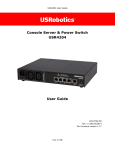
Console Server & Power Switch
USR4204
User Guide
R24.0792.00
Rev 1.2 10/16
Page 1 of 52
USR4204 User Guide
Contents
Contents ............................................................................................................. 2
Symbols Used In This User Guide ........................................................................... 4
Important Safety Instructions ................................................................................ 5
Introduction ........................................................................................................ 6
Overview of Main Features ................................................................................. 6
Package Contents ............................................................................................. 7
Physical Features .............................................................................................. 8
Getting Started – Local Access ............................................................................. 10
Physical Installation ............................................................................................ 11
Standalone ..................................................................................................... 11
Rack Mounting ................................................................................................ 11
Connecting Network Devices ............................................................................... 12
Connecting to Network Device Console Ports ...................................................... 12
Connecting To Power Ports ............................................................................... 12
Remote Access .................................................................................................. 13
Setting Up ...................................................................................................... 13
Remotely connecting and managing using dialup ................................................ 14
Product Operation .............................................................................................. 15
User interface ................................................................................................. 15
Security features ............................................................................................ 26
Flashing the firmware ......................................................................................... 32
Adding More Ports .............................................................................................. 33
Attaching a Slave USR4204 .............................................................................. 33
Addressing the Slave USR4204 ......................................................................... 33
Security Considerations ................................................................................... 33
Technical Specifications ...................................................................................... 34
Electrical ........................................................................................................ 34
Environmental ................................................................................................ 34
Product Dimensions and Weights ...................................................................... 35
FAQs and Troubleshooting ................................................................................... 36
General.......................................................................................................... 36
Configuring the USR4204 ................................................................................. 36
Remote Management ....................................................................................... 36
Page 2 of 52
USR4204 User Guide
Flashing firmware ........................................................................................... 36
Clearing A Forgotten or Disabled Administrator Name and Password ...................... 36
Suggested Security Guidelines .......................................................................... 37
What are "displayable characters"? ................................................................... 37
What are programmable characters? ................................................................. 37
Temporarily disabling Security .......................................................................... 37
Is there a maximum number of slave units that can be attached to a master
USR4204? ...................................................................................................... 38
Rackmounting the USR4204 with the back panel facing out .................................. 38
Support ............................................................................................................ 39
Appendix A ........................................................................................................ 41
Terminal Port and Serial Port RJ45 Pinout .......................................................... 41
RS-232 Adaptor Pinouts ................................................................................... 42
Straight and Rollover Cables............................................................................. 44
Legal Notice ...................................................................................................... 45
Warranty .......................................................................................................... 46
Regulatory Information ....................................................................................... 50
FCC Compliance .............................................................................................. 50
UL Listing/CUL Listing ...................................................................................... 50
Industry Canada (IC) ....................................................................................... 50
CE Compliance................................................................................................ 51
WEEE Compliance ........................................................................................... 51
Copyright Information ........................................................................................ 52
Page 3 of 52
USR4204 User Guide
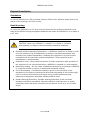
Symbols Used In This User Guide
This symbol alerts the user to important operating and maintenance
instructions.
This symbol warns the user that there are hazardous voltages within the
product enclosure.
This symbol invites the user to read more technical details.
This symbol identifies helpful user information.
This symbol warns the user to stop, read, and understand critical
information.
This symbol denotes supplemental information.
Page 4 of 52
USR4204 User Guide
Important Safety Instructions
SAVE THESE INSTRUCTIONS
This manual contains instructions and warnings that should be followed
during the installation, operation, and storage of this product. Failure to
heed these instructions and warnings may affect the product warranty.
WARNING: Hazardous Voltage! To reduce the risk of personal
injury from electric shock, do not remove the cover. There are
no field-serviceable or user-serviceable components inside.
Disconnect mains power from the product by unplugging the power cord from either
the electrical outlet or the product. The AC inlet is the main disconnect for removing
power to the product. For products that have more than one AC inlet, to remove
power completely, all AC line cords must be disconnected. The socket-outlet shall be
installed near the equipment and shall be easily accessible.
Disconnect mains power from the USR4204 before servicing equipment powered by
the USR4204.
Do not connect the product to an ungrounded outlet or to extension cords or
adapters that eliminate the connection to ground.
Before installing and using the product, check it for any external damage. If the
product is damaged, do not install or operate the product and contact your service
representative.
The product is designed for indoor use only in a controlled environment away from
excess moisture, temperature extremes, conductive contaminants, dust, or direct
sunlight.
DO NOT operate the product in an explosive atmosphere or in the presence of
flammable gases or fumes.
For continued protection against fire, replace the line fuse(s) only with fuse(s) of the
same voltage and current rating and type.
The total power requirement for equipment connected to the product must not
exceed the maximum output load rating(s).
Page 5 of 52
USR4204 User Guide
Introduction
Overview of Main Features
Out-of-Band Remote Management
Out-of-band remote management uses a secondary communications channel, typically a
pair of dial-up modems, to connect to the management ports of remote equipment and to
control outlets that supply power to the remote equipment. With one USR4204 a single
channel can control up to four management ports and two power ports. The USR4204 allows
a remote manager to select and control ports via a simple menu-driven interface.
Security
The USR4204 allows for one administrator and fifteen user accounts. The administrator can
create, delete, or edit user accounts, and has access to all USR4204 configuration menus.
The administrator can also assign access privileges for individual ports to each user. To
deter unauthorized access the USR4204 is configured to lockout user or administrator
accounts and display a security notification to users and the administrator in the event of
three consecutive failed attempts to log in as a user or administrator.
Page 6 of 52
USR4204 User Guide
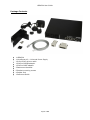
Package Contents
1
1
1
1
1
2
6
4
1
USR4204
VersaPower Kit – Universal Power Supply
6-foot RJ45 rollover cable
RJ45-to-DB25M adaptor
RJ45-to-DB9F adaptor
Rackmount brackets
Bracket mounting screws
Rubber feet
Reference Guide
Page 7 of 52
USR4204 User Guide
Physical Features
1. Terminal Port - RS-232 port for connection to modem or computer serial port to
configure and manage the USR4204 and connected devices.
The terminal port supports an RS-232 asynchronous serial DTE connection via an RJ45 jack.
See appendix A for pinout details. Terminal port activity can be monitored using the two
adjacent LEDs. Both LEDs light when the terminal or modem connected to this port signals
that it’s ready to receive or transmit data. For a terminal it is the DTR signal, for a modem it
is the DCD signal. The left LED flickers when data is transmitted from the terminal port, the
right LED flickers when data is received by the terminal port.
2. Serial Ports – Connect RS-232 network devices with RJ45 cables for device
management.
The four serial ports are RS-232 asynchronous serial DCEs presented on RJ45 jacks. See
appendix A for pinout details. Each serial port is represented by two adjacent LEDs, which
light when the port is selected. The left LED flickers when data is transmitted from the serial
port, the right LED flickers when data is received by the serial port.
3. Mains Input Port - Connect a C13 power cord from a nearby power outlet to the mains
input port to provide power to additional network devices.
The mains power input port is an IEC C14 fused inlet, rated for 8 amps maximum.
4. Power Output Ports - Connect power cords from up to two network devices (rated for a
total of 8 amps combined) for individual power management.
The power out ports are IEC C13 outlets, individually rated for 8 amps maximum.
WARNING: The combined power requirement of the equipment
connected to all the USR4204 outputs must not exceed the USR4204
maximum input rating of 8 Amps.
5. External Power Supply Input - Connect the included Versa Power Kit to power the
USR4204.
Page 8 of 52
USR4204 User Guide
The external power supply input delivers operating power to the USR4204 from the external
low voltage power supply that is included with the product.
Page 9 of 52
USR4204 User Guide
Getting Started – Local Access
This section describes how to verify the unit is operational. Once installed, this is also the
setup process for local access. For detailed unit configuration and advanced operating
features see Physical Installation, Remote Access, or Product Operation.
Step 1: Confirm package contents and check system requirements:
Computer terminal with a COM port
Terminal emulation application
Step 2: Connect the VersaPower™ Kit to the USR4204
Use the included VersaPower power supply to power the USR4204. The VersaPower power
supply includes blade clips compatible with mains power outlets in North America, UK, and
Europe. Remove the plastic protector from the VersaPower base unit, and slide in the
region-specific clip until it locks into place. Plug the power supply into a mains power outlet
and connect the VersaPower output jack to the USR4204 external power supply input.
Step 3) Open a Terminal Emulation Application
Open a terminal emulation window on the computer and select the COM port corresponding
to the computer’s serial port (usually COM1). Set the port parameters for 9600bps, 8 data
bits, no parity, 1 stop bit.
Refer to the terminal emulation application documentation for details on
setting parameters. Please set your application’s font for Courier, Courier
New, or another fixed character width font to properly display the menus.
Step 4) Connect a PC to the USR4204
Plug the included RJ45-to-DB9F adaptor into the computer’s DB9M serial port. Then connect
the adaptor’s RJ45 socket to the USR4204 terminal port using the included rollover cable.
If the terminal application raised the RS-232 DTR signal during initialization,
the USR4204 terminal port LEDs will light and the USR4204 will automatically
send its Main Menu screen to the terminal at 9600bps, 8N1 when you plug
into the terminal port.
Step 5) Confirm communication with the USR4204
In the terminal emulation window hit ENTER to show the Main Menu screen. If the Main
Menu does not appear on the terminal, remove power from the USR4204 and check the
Troubleshooting section.
You can now see the USR4204 parameter settings or enter any command displayed in the
Main Menu screen.
Congratulations!
The USR4204 is operational and ready to be installed at the equipment site.
Page 10 of 52
USR4204 User Guide
Physical Installation
Standalone
To use the USR4204 on a flat, horizontal surface, affix the four adhesive rubber feet to the
bottom of the housing in the four corners.
Rack Mounting
To mount the USR4204 in a 19" rack, securely fasten the two rackmount brackets to the
sides of the USR4204 using the supplied hardware and mount the USR4204 in a 1U space in
a 19" rack.
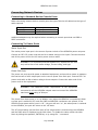
CAUTION: When the USR4204 is installed in a closed or multiunit
rack assembly, be aware of these potentially hazardous situations:
Elevated Ambient Operating Temperature – A USR4204 installed in a closed or multiunit rack assembly may be subjected to an ambient operating temperature that
exceeds room ambient temperature. Installing the equipment in an environment
compatible with the maximum ambient temperature (Tmax) specified by the
manufacturer is recommended.
Reduced Air Flow – Ensure that the amount of airflow required for safe operation of
the equipment is not compromised when a USR4204 is installed in a rack assembly.
Mechanical Loading – Do not create a hazardous condition by mounting the USR4204
in a rack that results in uneven or unbalanced mechanical loading.
Circuit Overloading - Consideration should be given to the connection of the
equipment to the supply circuit and the effect that overloading of the circuits might
have on overcurrent protection and supply wiring. Careful assessment and
awareness of equipment nameplate ratings should be used.
Reliable Earthing/Grounding - Reliable earthing/grounding of rack-mounted
equipment should be maintained. Particular attention should be given to supply
connections other than direct connections to the branch circuit (e.g. use of power
strips).
Page 11 of 52
USR4204 User Guide
Connecting Network Devices
Connecting to Network Device Console Ports
When connecting network device console ports the type of device will determine the type of
cable required.
Console Port
RJ45 DTE
RJ45 DCE
Cable
Straight Ethernet Cable
Rollover Cable
Additional adapters may be required when connecting to console ports that use DB9 or
DB25 connectors.
Connecting To Power Ports
Mains Input Port
The mains power input port is the source of power to both of the USR4204 power out ports.
Connect an IEC C13 power cord with an 8A or better rating to this input. Connect the other
end of the power cord to the AC mains power service outlet.
WARNING: For continued protection against fire, replace the line fuse
only with a fuse of the same voltage, current rating, and type.
Power Out Ports
The power out ports provide power to attached equipment, and provide a means to measure
the load current of each output port and to remove power from each port. Connect IEC C14
power cords with an 8A or better rating to these outputs. Connect the other end of the
power cords to the equipment.
WARNING: The combined power requirement of the equipment
connected to all the USR4204 outputs must not exceed the USR4204
maximum input rating of 8 Amps.
The power from these ports is 'on' by default, even when the USR4204 is unpowered. When
a power port is switched 'off', both the LINE and NEUTRAL conductors are opened. If the
USR4204 loses power while a port is 'off ', the port will turn 'on', but when power is restored
to the USR4204, the port will return to the 'off' state.
The AC current being sourced from each of the output ports is monitored by the USR4204
and the RMS value is displayed on the Main Menu. To update the value refresh the Main
Menu by hitting the spacebar, ENTER key or by using the '-' command.
Page 12 of 52
USR4204 User Guide
Remote Access
Setting Up
Confirm requirements:
Computer terminal with a COM port
Terminal emulation application
Modem at the management site
Modem at the equipment site
Access to phone line (analog connection only) or Cellular service (cellular connection
only) at both locations
To remotely connect to the USR4204, the modem must be configured before connecting it
to the USR4204 at the equipment site.
Configuring the Modem
The modem connected to the USR4204 must be pre-configured for result codes disabled,
local echo disabled, auto-answer enabled, AT commands disabled (“Dumb mode”), and a
fixed DTE rate of 9600bps, 8N1. To set the modem DTE rate, use a terminal set at 9600bps,
8N1 to send commands to the modem to establish the modem DTE rate. Disable result
codes, disable local echo, enable auto-answer, and then store the updated settings into
modem memory. Then disable AT commands, which is normally done by flipping a physical
switch on the modem. Consult the modem’s user guide for details.
The modem should not override the Carrier Detect signal and Error Correction
should be enabled, which are typically default modem settings.
If the equipment being managed through the USR4204 uses serial rates
different from 9600bps, XON/XOFF flow control may need to be enabled in
the USR4204 and in the modem to prevent buffer overflow.
Connecting the Modem
Once the modem has been properly configured, it may be attached to the USR4204 terminal
port and telephone line.
Modem Connector
Adaptors and Cables Needed
DB25F
Provided DB25 Adapter and provided RJ45 rollover cable.
DB9F
Select one of the following:
Purchase a RJ45-to-DB9M null modem adaptor and use
the provided RJ45 rollover cable.
Purchase a RJ45-to-DB9M adaptor and use a straight
Ethernet cable.
Purchase a DB25F-to-DB9M adaptor and use the
provided RJ45-to-DB25M adaptor and RJ45 rollover
cable.
See appendix A for the wiring diagrams for all options.
Page 13 of 52
USR4204 User Guide
The attached equipment is now ready to be remotely managed.
Remotely connecting and managing using dialup
To connect to the USR4204 and manage the attached devices at the equipment site, the
user will need a terminal emulation application, a connected modem, and a phone line at
the management site.
From the terminal, dial the phone number of the modem at the equipment site.
Once the modems connect, the USR4204 will send the Main Menu or login prompt to the
management terminal.
If the Main Menu or login prompt does not automatically appear hit ENTER. If
the Main Menu or login prompt still does not appear on the terminal check the
Troubleshooting section.
Page 14 of 52
USR4204 User Guide
Product Operation
User interface
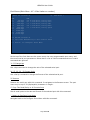
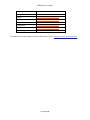
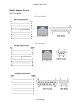
The USR4204 user interface is organized into menus. See Figure 1 for a map of all menus.
Each menu contains commands, text, and status where appropriate. Commands listed on
the following pages are shown within single quotes ('), programmable names are shown
within double quotes ("). Commands are single characters that either perform an action or
provide navigation to another menu. Commands are not case-sensitive. Text can be any
alphanumeric or punctuation characters.
Alphanumeric and punctuation include all ASCII characters from 20h to 7Eh.
To access the User Interface open a terminal emulation window on a computer (using
Courier or other fixed-width font) and connect to the USR4204 remotely via modem or
locally via the terminal port using a rolled RJ45 cable. Hit ENTER to show the Main Menu
screen. If security is enabled the login prompt will appear.
Hit the spacebar or the Enter key to refresh any Menu within the User
Interface.
Page 15 of 52
USR4204 User Guide
Figure 1
Login Screen
(If security is enabled)
Main Menu
Arm Ctrl-B
for Break
Menu (W)
Configure
Parameters
Menu (Y)
Configure
Security
Menu (U)
Configure Port
Menu (Z)
Port
Menus
Admin
Password
Menu (0)
User
Menus
Note: Menus with red borders are not available to users if security is enabled
Page 16 of 52
USR4204 User Guide
Command Reference
Command
Connect to Port
Toggle Power Port On or Off
Arm Ctrl-B for Break
Configure Port Parameters
Rename Power Port
Rename Console Port
Copy Baud Rate and Parity to all Console Ports
Change Console bps rate
Change Console parity
Configure Parameters
Change Inactivity Timeout
Customize USR4204 Name
Change Char for Escape
Change Char for Menu
Change Char for Xon
Change Char for Xoff
Toggle Cellular Mode
Enter Login Banner
Enter Security Banner
Toggle S/W Flow Control
Toggle Xon/Xoff Pass Thru
Toggle Command Echo
Toggle Auto CR
Toggle DCD Override
Toggle Security Banner
Config Security (Manage Users and turn on Security)
Load Factory Parameters
Flash New Code
Turn on Security/Create an Admin
Change Admin Username
Change Admin Password
Create/Manage a User
Change User Username
Change User Password
Remove all User Accounts including Admin.
Turn off Security.
Change User Port Permissions
Deny Access to all Ports
Grant Access to all Ports
Turn User on or off
Toggle Administrator Privileges
Delete User
Return to parent menu
Logout
Keystrokes
Mm PL
Mm P# (Y,N)
Mm W PL
Mm Z PL
Mm Z P#
Mm Z PL R
Mm Z PL C
Mm Z PL (1-9)
Mm Z PL (NEOMS)
Mm Y
Mm Y T
Mm Y R
Mm Y S
Mm Y M
Mm Y N
Mm Y X
Mm Q
Mm Y W
Mm Y Y
Mm Y F
Mm Y P
Mm Y E
Mm Y A
Mm Y D
Mm Y B
Mm Y U
Mm Y &
Mm Y !
Mm Y U 0
Mm Y U 0 Y
Mm Y U 0 Z
Mm Y U UID
Mm Y U UID Y
Mm Y U UID Z
Mm Y U &
Availability
NS, A, AU
NS, A, AU
NS, A, AU
NS, A
NS, A
NS, A
NS, A
NS, A
NS, A
NS, A
NS, A
NS, A
NS, A
NS, A
NS, A
NS, A
NS, A, AU
NS, A
NS, A
NS, A
NS, A
NS, A
NS, A
NS, A
NS, A
NS, A
NS, A
NS, A
NS, A
NS, A
A
A
A
A
A
Mm
Mm
Mm
Mm
Mm
Mm
A
A
A
A
A
A
NS, A, AU
A, AU
YU
YU
YU
YU
YU
YU
Mm X
UID
UID
UID
UID
UID
UID
PL/P#
W
S
T
P
X
NOTE: Italics indicate that a specific port or user must be selected.
Parentheses indicate multiple options – verify choice on screen.
Key:
Mm Main Menu
PL Console Port Letter (A-D)
P# Power Port Number (1-2)
NS No Security
A Admin
AU Approved user
Page 17 of 52
UID User account number or
letter (1-9, A-F)
USR4204 User Guide
Main Menu
T/O Esc Menu Xon Xoff Flow Pass Echo AutoCR DCD Banr
005 - ^Q
^S
OFF OFF ON
ON
OFF OFF
---------------------------------------------------MAIN Menu "USR4204
" Logged In: "Admin Username
CMD
'A'
'B'
'C'
'D'
Connect
Connect
Connect
Connect
"Console
"Console
"Console
"Console
A
B
C
D
'1' Toggle
'2' Toggle
"Power 1
"Power 2
'Q'
'W'
'X'
'Y'
'Z'
Cellular Mode (OFF)
Ctrl-B for Break
Toggle
Arm
Logout
Config
Config
"(
"(
"(
"(
"(ON
"(ON
9600
9600
9600
9600
None
None
None
None
"
)
)
)
)
0.0 Amps)
0.0 Amps)
Parameters
Ports
'-' Refresh MAIN Menu
At the top of the Main Menu is a banner that displays the current system parameters. Below
the banner are the menu name, the user-programmable device name, and the current login
name (if security is enabled). Next is a list of valid commands, text, and status. Invalid
commands are ignored.
Commands listed in this guide are shown within single quotes ('),
programmable names are shown within double quotes (")
'A'-'D' Connect to Console
A Connect command creates a full duplex data connection between the USR4204 terminal
port and one of its serial ports. The terminal port is fixed at 9600bps, 8N1. The rate and
format of serial ports are programmable to match the console port of the attached
equipment. The current serial port parameters are shown in parentheses next to the port
name.
To close a connection to a serial port, use the Escape Sequence. The Escape
Sequence consists of three identical characters typed rapidly without
surrounding characters. The default Escape character is "-" and is shown in
the banner on the Main Menu.
'1'- '2' Toggle Power Port
A Toggle command controls a power port. When a Toggle command is entered, power from
the mains power input is disconnected or reconnected to the corresponding output after
Page 18 of 52
USR4204 User Guide
entering a ‘Y’ at the “Are you sure?” prompt. The current power port state (ON or OFF) and
RMS load current are shown in parentheses next to the port name.
To update the value refresh the Main Menu by hitting the spacebar, ENTER key, or by using
the Refresh Menu (default '–') command.
'Q' Toggle Cellular Mode
Each press of the 'Q' command cycles from 0 (OFF) through 7.
OFF: The Escape Sequence behaves normally for analog modem connections. Three
consecutive characters (default '-') causes a disconnect from a Serial Port connection. There
is a one second maximum guard time allowed between the characters.
1-7: These settings are for Cellular (packet) connections, where large variations in latency
may occur. The specified number (1 thru 7) of the programmed escape sequence characters
(default '–') causes a disconnect from a Serial Port connection. The one second maximum
guard time limit is disabled.
'W' Arm Ctrl-B for Break
Navigate to the Arm Ctrl-B for Break Menu for selection of which serial port will enable and
send a break signal.
'X' Logout
The Logout command ends a secure session and sends the Login screen to the terminal. It
is only available when security is on.
'Y' Configure Parameters
Navigate to the Configure Parameters Menu with this command.
'Z' Configure Ports
Navigate to the Configure Ports Menu with this command.
The Configure Parameters and Configure Ports commands are available only
to the administrator, or if security is off.
'-' Refresh MAIN Menu
Refresh Main Menu banner with current system parameters and update current status for
each port with this command.
The spacebar or the Enter key may also be used to refresh the Main Menu.
Page 19 of 52
USR4204 User Guide
Arm Ctrl-B for Break Menu (Main Menu W)
'W' Arm
Ctrl-B for Break - Select Port:
CMD
'A'
'B'
'C'
'D'
"Console
"Console
"Console
"Console
Connect
Connect
Connect
Connect
A
B
C
D
"(
"(
"(
"(
9600
9600
9600
9600
None
None
None
None
)
)
)
)
'-' Refresh MAIN Menu
At the top of the Arm Ctrl-B for Break Menu is the menu name. Below that is a list of valid
commands, text, and status. Invalid commands are ignored.
'A'-'D' Connect to Console
A Connect command creates a full duplex data connection between the USR4204 terminal
port and one of its serial ports, and arms a control-B character. While connected to the
selected port, the user must manually send a RS-232 break signal by hitting the Ctrl-B keys
at the appropriate time. Once Ctrl-B has been entered any subsequent Ctrl-B characters will
be recognized as ordinary data instead of breaks.
The current serial port parameters are shown in parentheses next to the port name.
To close a connection to a serial port, use the Escape Sequence. The Escape
Sequence consists of three identical characters typed rapidly without
surrounding characters. The default Escape Sequence command is "---".
Page 20 of 52
USR4204 User Guide
Configure Ports Menu (Main Menu Z)
Configure Ports Menu "USR4204
CMD
'A'
'B'
'C'
'D'
Config
Config
Config
Config
"Console
"Console
"Console
"Console
'1' Rename
'2' Rename
"Power 1
"Power 2
'-' Return
to MAIN Menu
"
A
B
C
D
"(
"(
"(
"(
9600
9600
9600
9600
"(ON
"(ON
None
None
None
None
)
)
)
)
0.0 Amps)
0.0 Amps)
At the top of the Configure Ports Menu are the menu name and the user-programmable
device name. Below that is a list of valid commands, text, and status. Invalid commands are
ignored.
'A'-'D' Config Console Port
Navigate to the Port Menu of the corresponding serial port to change the rate, format, or
name of the selected port with this command. The current serial port parameters are shown
in parentheses next to the port name.
'1'-'2' Rename Power Port
Navigate to the Rename screen of the corresponding power port to change the name of a
power port with this command. The port name may be up to 32 (displayable) characters in
length. The current power port state (ON or OFF) and RMS load current are shown in
parentheses next to the port name.
'-' Return to MAIN Menu
Navigate back to the Main Menu with this command.
Page 21 of 52
USR4204 User Guide
Port Menus (Main Menu Z Port Letter or number)
Menu for "Console A
CMD
'1'
300
'2'
1200
'3'
2400
'4'
4800
'5'
9600
'6' 19200
'7' 38400
'8' 57600
'9' 115200
bps
bps
bps
bps
bps
bps
bps
bps
bps
CMD
'N'
'E'
'O'
'M'
'S'
"(
8
7
7
7
7
Data
Data
Data
Data
Data
Bits,
Bits,
Bits,
Bits,
Bits,
Parity
Parity
Parity
Parity
Parity
9600 None )
None
Even
Odd
Mark
Space
'R' Rename "Console A
"
'C' Copy This Baud/Parity to All Console Ports
'-' Return
to Configure Ports Menu
At the top of the Port Menu are the menu name, the user-programmable port name, and
the current serial port parameters. Below that is a list of valid commands and text. Invalid
commands are ignored.
'1'–'9' Change bps
Use a bps command to change the rate of the selected serial port.
'N', 'E', 'O', 'M', 'S' Change Parity
Use a Parity command to change the format of the selected serial port.
'R' Rename
Rename the serial port with this command. It navigates to the Rename screen. The port
name may be up to 32 (displayable) characters in length.
'C' Copy This Baud/Parity to All Console Ports
Set all serial ports to the rate and format of the selected port with this command.
'-' Return to Configure Ports Menu
Navigate back to the Configure Ports Menu with this command.
Page 22 of 52
USR4204 User Guide
Configure Parameters Menu (Main Menu Y)
T/O Esc Menu Xon Xoff Flow Pass Echo AutoCR DCD Banr
005 - ^Q
^S
OFF OFF ON
ON
OFF OFF
---------------------------------------------------Configure Parameters Menu Ver 1.12 09/18/13 S/N: 1ME4Z7PM0004
CMD
'T'
'S'
'N'
'W'
Change
Change
Change
Enter
Inactivity Timeout
Char for Escape
Char for Xon
Login Banner
CMD
'R'
'M'
'X'
'Y'
Rename
Change
Change
Enter
System
Char for Menu
Char for Xoff
Security Banner
'F'
'E'
'D'
'U'
Toggle
Toggle
Toggle
Config
S/W Flow Control
Command Echo
DCD Override
Security
'P'
'A'
'B'
'&'
Toggle
Toggle
Toggle
Load
Xon/Xoff Pass Thru
Auto CR
Security Banner
Factory Parameters
to MAIN Menu
'!' Flash
'-' Return
New Code
At the top of the Configure Parameters Menu is a banner that displays the current system
parameters. Directly below the banner are the menu name, the user-programmable device
name, the firmware version number and date, and the serial number of the USR4204. Below
that is a list of valid commands and text. Invalid commands are ignored.
'T' Change Inactivity Timeout
The USR4204 will close a serial port if no data passes in or out of the terminal or serial port
before this inactivity time lapses. If security is enabled, the session will also logout.
Valid range: 0 to 255 minutes (0 disables the timer)
Default: 005
'R' Rename
Rename the USR4204 with this command. It navigates to the Rename screen. The USR4204
name may be up to 32 (displayable) characters in length.
Default: USR4204
'S' Change Char for Escape
Change the Escape Sequence character with this command. It navigates to the Change
Character screen.
The Escape Sequence may be disabled by programming this character to a control-\. To
enter control-\ in the Change Character screen, hold down the Ctrl key and press \
Page 23 of 52
USR4204 User Guide
Default: "-"
Hexadecimal 1Ch is ASCII character ^\ (Ctrl-\).
'M' Change Char for Menu
Change the character for the View Menu command with this command. It navigates to the
Change Character screen.
Default: "-"
'N' Change Char for Xon
Change the character used for Xon flow control with this command. It navigates to the
Change Character screen.
Default: 11h
Hexadecimal 11h is ASCII character ^Q (Ctrl-Q).
'X' Change Char for Xoff
Change the character used for Xoff flow control with this command. It navigates to the
Change Character screen.
Default: 13h
Hexadecimal 13h is ASCII character ^S (Ctrl-S).
'W' Enter Login Banner
When security is enabled, the USR4204 will present this greeting followed by a login
prompt. This command navigates to the Change Banner screen. The banner may be up to
64 (displayable) characters in length.
Default: USRobotics Console Server & Power Switch
'Y' Enter Security Banner
If security and the security banner are enabled, the USR4204 will present a security banner
prior to the login banner. This command is only available when security is on and navigates
to the Change Banner screen. The banner may be up to 256 (displayable) characters in
length. Each occurrence of '\n' (newline) will be replaced with a carriage return/line feed
pair.
Page 24 of 52
USR4204 User Guide
Default: empty (nulls)
The security banner is enabled or disabled by the 'B' command in the Configure Parameters
Menu.
'F' Toggle S/W Flow Control
Enable or disable Xon/Xoff flow control for the terminal port and all serial ports with this
command.
Default: Off
If S/W flow control is desired, it must be enabled on both the USR4204 and
the modem.
'P' Toggle Xon/Xoff Pass Thru
Xon/Xoff flow control characters are allowed to pass through the terminal port and all serial
ports with this command.
Default: Off
'E' Toggle Command Echo
The terminal port can echo back to the terminal all valid commands and text it received.
Disable or re-enable echoing with this command.
Default: On
'A' Toggle Auto CR
The terminal port can accept single digit commands without an explicit carriage return
(0Dh). Disable or re-enable Auto CR with this command.
Default: On
'D' Toggle DCD Override
The terminal port can monitor the incoming DCD (or DTR) signal. When DCD is not
overridden, a rising edge will cause the terminal port to send the main menu or the login
prompt. A falling edge will close any open serial port, and logout the session if security is
enabled. Enable or disable DCD override with this command.
Default: Off
'B' Toggle Security Banner
If security is enabled, the USR4204 may present a security banner ahead of the login
prompt. Enter the security banner text with the 'Y' command in the Configure Parameters
Page 25 of 52
USR4204 User Guide
Menu. Enable or disable the security banner with this command, which is available only
when security is on.
Default: Off
'U' Config Security
Setup and manage Administrator or User accounts with this command. It navigates to the
Configure Security Menu.
'&' Load Factory Parameters
Restore factory defaults to all system parameters shown in the banner with this command.
'-' Return to MAIN Menu
Navigate back to the Main Menu with this command.
'!' Flash New Code
The USR4204 erases current firmware and prepares for new firmware file to be installed.
See Flashing the Firmware for detailed instructions.
Security features
The USR4204 defaults to security disabled. To enable security create an Admin user. From
the Main Menu go to the Configure Parameters Menu ('Y'), then Config Security ('U'), then
Select Admin ('0'), and enter an Administrator name and password.
When security is enabled:
The Administrator has access to all ports and menus. Users have access to ports
allowed by the Administrator.
Up to fifteen User accounts may be created, edited, or deleted by the Administrator.
Each User may be granted or denied access to each serial and power port.
Only the Administrator has access to configuration menus.
Individual Users may be granted Administrator privileges
The USR4204 will generate a notification if three consecutive login attempts fail. The
notification is displayed prior to the Main Menu Screen following a successful login. A
successful Administrator login clears the notification.
If the three consecutive failed login attempts match a registered username, that user
account will be disabled until the administrator re-enables it.
Disable security by deleting the admin account. The administrator account can only
be deleted by removing all accounts in the Configure Security Menu.
If the three consecutive failed login attempts match the administrator
name, the administrator account will be disabled. The administrator
account can only be re-enabled from the remote site with the
Page 26 of 52
USR4204 User Guide
USR4204. See "Clearing A Forgotten or Disabled Administrator Name
and Password" for details.
See FAQs and Troubleshooting for suggested security guidelines.
Config Security Menu (Main Menu Y U)
Configure Security Menu
CMD
'0'
'1'
'2'
'3'
'4'
'5'
'6'
'7'
Select
Select
Select
Select
Select
Select
Select
Select
'-' Return
(current enabled state in parentheses below)
"Admin Username
"
"
"
"
"
"
"
"
"
"
"
"
"
"
"
Admin
(OFF)
(OFF)
(OFF)
(OFF)
(OFF)
(OFF)
(OFF)
to Config Parameters Menu
CMD
'8'
'9'
'A'
'B'
'C'
'D'
'E'
'F'
Select
Select
Select
Select
Select
Select
Select
Select
"
"
"
"
"
"
"
"User 15
"
"
"
"
"
"
"
"
(OFF)
(OFF)
(OFF)
(OFF)
(OFF)
(OFF)
(OFF)
(ON )
'&' Remove ALL Accounts
At the top of the Configure Security Menu is the menu name. A list of valid commands, text,
and status follows. Invalid commands are ignored.
Use a Select command (see below) to set up the Administrator and up to 15 User accounts.
'0' Select Admin
Navigate to the Administrator Menu with this command. It is the only command available if
security is off. Use this command to setup the Administrator account and turn on security.
'1'–'9' and 'A'–'F' Select User
Navigate to the corresponding User Menu with this command. The current User status
(ON/OFF) is shown in parentheses next to the User name. Use this command to setup a
User account.
NOTE: To re-enable a disabled or locked out user, select the user then Toggle
the User Enable status to 'ON'.
Page 27 of 52
USR4204 User Guide
'-' Return to Configure Parameters Menu
Navigate back to the Configure Parameters Menu with this command.
'&' Remove ALL Accounts
Disable security and clear all user accounts including the Administrator with this command.
There is a confirmation prompt before deletion.
Administrator Password Menu (Main Menu Y U 0)
"Admin Username
" Admin Password Menu
CMD
'Y' Change
'Z' Change
Username
Password
'-' Return
to Configure Security Menu
At the top of the Administrator Password Menu is the programmable Administrator name
and the menu name. Below that is a list of valid commands. Invalid commands are ignored.
'Y' Change Username
This command navigates to the Change Administrator username screen. The username
may be up to 16 (displayable) characters in length.
'Z' Change Password
Use the Change Password command to enter the Administrator password on the Change
Password screen. The password may be up to 13 (displayable) characters in length.
The Change Password command appears only after a Username is entered.
Administrator username and password are case-sensitive.
Page 28 of 52
USR4204 User Guide
Security is enabled by entering an Administrator username and password.
'-' Return to Configure Security Menu
Navigate back to the Configure Security Menu with this command.
Do not forget the administrator name and password! Record and
store all Administrator and User information in a secure location. The
recovery method requires you to be at the physical location of the
USR4204. See "Clearing A Forgotten or Disabled Administrator Name
and Password" for details.
User Menu (Main Menu Y U number or letter of user)
"User 15
CMD
'A'
'B'
'C'
'D'
" User Menu
Toggle
Toggle
Toggle
Toggle
"Console
"Console
"Console
"Console
'1' Toggle
'2' Toggle
"Power 1
"Power 2
'Y'
'Z'
'W'
'S'
'T'
'P'
'X'
Username
Password
All Permissions
All Permissions
User Enable (ON )
Admin Privil (OFF)
User
Change
Change
Deny
Grant
Toggle
Toggle
Delete
'-' Return
(current permissions in parentheses below)
A
B
C
D
"
"
"
"
(ON
(ON
(ON
(ON
)
)
)
)
" (ON )
" (ON )
to Configure Security Menu
At the top of the User Menu are the programmable User name and the menu name. Below
that is a list of valid commands, text, and status. Invalid commands are ignored.
Only the Change Username command ('Y') appears until a Username is entered.
'A'-'D', '1'-'2' Toggle Port Permissions
Grant or deny access to the corresponding port for the selected User.
Page 29 of 52
USR4204 User Guide
'Y' Change Username
This command navigates to the Change Username screen. The username may be up to 16
(displayable) characters in length, but may not be blank. Usernames are case-sensitive.
'Z' Change Password
Use the Change Password command to enter the password on the Change Password screen.
The password may be up to 13 (displayable) characters in length. Passwords are casesensitive.
A User account password is optional. If no password is entered, the User can hit
the enter key to skip the password prompt in the Login Screen.
'W' Deny All Permissions
Deny the selected User access to all ports with this command.
'S' Grant All Permissions
Grant the selected User access to all ports with this command.
'T' Toggle User Enable
Enable or disable the selected User’s login with this command. Current status is indicated in
parentheses.
‘P’ Toggle Administrator Privileges
Enable or disable Administrator privileges to a User with this command. Current status is
indicated in parentheses.
'X' Delete User
Remove all User information including permissions, username, and password with this
command. Delete users with this delete command or the Remove All Accounts command in
the Configure Security Menu.
'-' Return to Configure Security Menu
Navigate back to the Configure Security Menu with this command.
Page 30 of 52
USR4204 User Guide
Login Screen
USRobotics Console Server & Power Switch
Login:
Once security is enabled the user interface will always first display the Login Screen until
security is disabled. The Administrator or any enabled User may login from this screen.
Page 31 of 52
USR4204 User Guide
Flashing the firmware
The USR4204 uses two pieces of flash memory for its operation – boot code and system
code. Flashing the firmware replaces the system code.
Before flashing, the firmware file must already be downloaded from the USR4204 support
webpage to a hard drive accessible from the management terminal. Note the location of
the file. Also, be sure to note how to send files with the terminal application being
used. Read all steps for flashing the firmware before you begin.
Step 1: Choose the Flash New Code command ('!') from the Configure Parameters Menu to
put the USR4204 into Boot Mode.
Step 2: At the "Are you sure?" prompt, type 'Y'.
NOTE: To abort or to exit Boot Mode without flashing, type '!' at the Boot>
prompt. The USR4204 restarts and goes to Main Menu (or Login screen if
security is on).
WARNING: Step 3 erases system code. The system will no
longer be operational until firmware is uploaded.
Step 3: Type '#$%' at the Boot> prompt. "Please wait" will appear while the system code
is erased. When complete, "LOAD HEX FILE" appears. The USR4204 is now in file receive
mode.
NOTE: File upload must be started within 30 seconds or you will be returned
to the Boot> prompt. To continue the upload process from the Boot>
prompt, repeat step 3.
Step 4: Use an application (HyperTerminal, ProComm Plus, etc.) to send the .hex file (in
ASCII) to the USR4204. The process will take about 30 seconds. When complete, the
USR4204 restarts and goes to Main Menu (or Login screen if security is on).
If upload is interrupted or the file is corrupt, the USR4204 will return to the
Boot> prompt. Check the Troubleshooting Section for possible causes.
Page 32 of 52
USR4204 User Guide
Adding More Ports
If more serial or power ports are needed, purchase an additional USR4204 (slave) and
connect it to the master USR4204.
Attaching a Slave USR4204
Use a straight Ethernet cable (see appendix A) to connect any available USR4204 serial port
to the terminal port of the slave USR4204. The serial port parameters must be 9600bps,
8N1.
Addressing the Slave USR4204
To access the menus of the slave USR4204, select the serial port that connects it to the
master USR4204 from the Main Menu. Enter any command in the slave USR4204 Main
Menu, including the View Menu command (hit ENTER). To return to the master USR4204
Main Menu, type the USR4204 escape code (default "---").
NOTE: It is recommended to rename each USR4204 to a unique name for easier
identification.
If the slave USR4204 has a serial port selected, the escape code will close the
port, exit from the slave USR4204, and return to the master USR4204 Main
Menu.
Security Considerations
If the master USR4204 has security enabled, the administrator should choose whether
security is disabled or enabled in the slave USR4204.
If the administrator chooses to allow users access to all menus and ports in the slave
USR4204, security must be disabled in the slave USR4204. Users that log in to the master
USR4204 and have permission to access the serial port connected to the slave USR4204 will
then have access to all menus and ports in the slave USR4204.
If the administrator chooses to restrict users from accessing configuration menus and
certain ports in the slave USR4204, the slave USR4204’s security must be enabled. The
administrator must create additional user accounts in the slave USR4204, and set each of
those user’s permissions to access ports. Users that log-in to the master USR4204 and have
permission to the serial port connected to the slave USR4204 will have to enter a valid
username and password into the slave USR4204 to access its ports.
Page 33 of 52
USR4204 User Guide
Technical Specifications
Electrical
RS-232 DTE Terminal Port
Data rate: 9600 bps
Asynchronous data format: 8 data bits, no parity, 1 stop bit
4-wire interface: RXD,TXD,DTR,DSR (See appendix A for pinout)
RS-232 DCE Serial Ports
Supported data rates: 115200, 57600, 38400, 19200, 9600, 4800, 2400, 1200, and
300 bps
Supported asynchronous data formats:
o 8 data bits, no parity, 1 stop bit
o 7 data bits, odd parity, 1 stop bit
o 7 data bits, even parity, 1 stop bit
o 7 data bits, mark parity, 1 stop bit
o 7 data bits, space parity, 1 stop bit
2-wire interface: RXD,TXD (See appendix A for pinout)
Mains Power Input Port
Connector: IEC C14
Voltage: 250 Vac maximum
Current: 8A maximum continuous
Fuse: 8A, 250 Vac, 5 x 20mm, time-delay, ceramic (IEC type T8AH250V)
Power Output Ports
Connector: IEC C13
Voltage: 250 Vac maximum
Current: 8A maximum continuous
Switching: 2-pole, normally closed (2 Form B)
Current measurement range: 0-8.5 A (RMS)
Current measurement accuracy: ±0.2 A
Power supply input
Voltage: 12-20 Vdc (either polarity), or 8-15 Vac
Plug dimensions: 5.5mm o.d. x 2.5mm i.d. x 9.5mm length
Power Consumption
1.5 W (typical)
1.8 W (maximum)
Environmental
Temperature
Operating Temperature conditions: 0 to 50 degrees C,
Non-Operating Temperature conditions: -20 to 70 degrees C
Page 34 of 52
USR4204 User Guide
Humidity
Operating Humidity conditions: 20% to 80% non-condensing,
Non-Operating Humidity conditions: 5% to 95% non-condensing
Product Dimensions and Weights
Dimensions
W x H x L: 9.96 x 1.71 x 7.75 in (25.3 x 4.34 x 19.7 cm) (without rubber feet)
W x H x L: 9.96 x 1.94 x 7.75 in (25.3 x 4.92 x 19.7 cm) (with rubber feet)
1U 19” rack space (with rack brackets attached)
Weight
2.25 lbs (1.02 kg)
Page 35 of 52
USR4204 User Guide
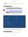
FAQs and Troubleshooting
General
If you have trouble with the USR4204 first try the following:
Try removing the power and repeating the setup process.
Make sure the correct COM port was selected.
Make sure the modem was setup properly.
Make sure the power supply is plugged in to an operational power outlet, and that
the power supply is also securely plugged into the unit.
Verify all cables and adaptors are correct for the type of ports.
When connected hit ENTER to see if the Main Menu appears on the terminal.
Configuring the USR4204
How to configure flow control in a setup with added ports:
To enable flow control on a slave USR4204, both the slave and the modem need to have
flow control enabled, but the master must have flow control turned OFF. When two or more
slave USR4204s are chained to a single master serial port, enable flow control in the
modem and only the last slave USR4204 in the chain.
Remote Management
Management modem fails to connect to remote modem:
Refer to your modem troubleshooting documentation.
Check modem phone numbers
Modems connect but fail to show USR4204 interface on the management terminal:
Check for carrier detect override (hit ENTER)
Try general USR4204 troubleshooting.
Flashing firmware
Possible Causes for firmware flash failure:
Phone line was disconnected. Confirm it is connected and functional, then reconnect
and try firmware flash again.
File was corrupt. Re-download file and try firmware flash again.
Firmware flash continues to fail. Try firmware flash again using previous working
version or original firmware available from usr.com.
Clearing A Forgotten or Disabled Administrator Name and Password
Disconnect the low voltage power supply from the USR4204, connect a straight Ethernet
cable from the USR4204 terminal port to serial port A, and then re-apply power to the
USR4204. The USR4204 will clear the administrator name and password. You may then
connect a terminal to the USR4204 terminal port to enter a new administrator name and
password. User accounts are unaffected.
Page 36 of 52
USR4204 User Guide
Suggested Security Guidelines
Creating usernames and passwords
Create Usernames and Passwords that are not easy to guess.
Use at least 8 characters.
Use upper/lowercase letters, numbers, and punctuation characters.
Consider using 2 spaces instead of 1 between words.
Consider beginning with a space, a number, or a punctuation character.
o Example: "John Smith" might be better as " J0hn $m!Th"
Hacker consequences
If someone tries to hack in with a valid Username three consecutive times, that user
will be locked out until the administrator re-enables the account.
If the hacked Username is the Administrator's, the above procedure (Clearing a
Forgotten or Disabled Administrator Name and Password) will be required onsite. (i.e. don't use "admin")
Security Features to use or enable
Don't disable the Inactivity Timer. This ensures that the system is available for users
who are actually using it.
Program the Security Banner. Use warning text appropriate for your installation.
What are "displayable characters"?
"Displayable characters" are all chars from 20h thru 7Eh.
What are programmable characters?
All 4 of the programmable characters (escape sequence, return to parent menu, Xon, Xoff)
can be any of the following displayable characters:
%()*-/@[\]_{|}~
Or any of the following control characters: A B C D E F G I K L N O P Q R S T U V W X Y Z \
]^_
Temporarily disabling Security
There is no way to temporarily disable security. The Admin must be deleted using the
"Remove all Accounts" command, which will turn off security and remove all accounts that
were created. To turn security back on, a new Admin must be created as well as any other
accounts and permissions.
Page 37 of 52
USR4204 User Guide
Is there a maximum number of slave units that can be attached to a
master USR4204?
No, there is no maximum. But as the hierarchy grows, the path can become more
complicated - especially if security is on, as each step in the path would require a separate
username and password.
Rackmounting the USR4204 with the back panel facing out
When rackmounted, the USR4204 front panel will face out by default, but it can be
rackmounted with the back panel facing out.
1. WARNING: Remove all power cords from the USR4204 to prevent shock hazard.
2. Unscrew and remove the rackmount brackets if necessary.
3. Unfasten the top housing by unscrewing the six (6) Phillips-head screws. Save the
screws for step 5.
4. Remove the top housing and position it so the bracket mounting holes are near the
rear panel.
5. Replace the top housing and fasten it with the six (6) Phillips-head screws.
6. Follow the instruction in the Physical Installation section to attach the rackmount
brackets to the USR4204 and install in a rack.
If these troubleshooting tips did not solve your issue contact USRobotics technical support.
Page 38 of 52
USR4204 User Guide
Support
1. Be prepared to provide model and serial numbers.
Product
Model Number
USRobotics Console Server & Power Switch
4204
The USR4204 serial number is on the side of the package, bottom of the unit, and
listed in the user interface at the top right of the Configure Parameters Menu.
2. Visit the Support section of the USRobotics Web site at www.usr.com/support/4204
Many of the most common issues that users experience have been addressed in the
FAQ and Troubleshooting Web pages for the USR4204. The Support Web pages also
contain information on the latest firmware and documentation updates.
3. Submit a technical support question to the USRobotics Technical Support Department
using an online form:
Country
Webmail
United States & Canada
http://www.usr.com/emailsupport
Country
Webmail
Austria
www.usr.com/emailsupport/de
Belgium (Flemish)
www.usr.com/emailsupport/nl
Belgium (French)
www.usr.com/emailsupport/be
Czech Republic
www.usr.com/emailsupport/cz
Denmark
www.usr.com/emailsupport/ea
Finland
www.usr.com/emailsupport/ea
France
www.usr.com/emailsupport/fr
Germany
www.usr.com/emailsupport/de
Greece
www.usr.com/emailsupport/gr
Hungary
www.usr.com/emailsupport/hu
Ireland
www.usr.com/emailsupport/uk
Italy
www.usr.com/emailsupport/it
Luxembourg
www.usr.com/emailsupport/be
Netherlands
www.usr.com/emailsupport/nl
Norway
www.usr.com/emailsupport/ea
Poland
www.usr.com/emailsupport/pl
Page 39 of 52
USR4204 User Guide
Country
Webmail
Portugal
www.usr.com/emailsupport/pt
Russia
www.usr.com/emailsupport/ru
Spain
www.usr.com/emailsupport/es
Sweden
www.usr.com/emailsupport/se
Switzerland
www.usr.com/emailsupport/de
Turkey
www.usr.com/emailsupport/tk
United Kingdom
www.usr.com/emailsupport/uk
For additional current support contact information, go to: www.usr.com/international.asp
Page 40 of 52
USR4204 User Guide
Appendix A
Terminal Port and Serial Port RJ45 Pinout
Terminal Port RJ45 Pinout
RJ45 Pin
Symbol
Description
Direction
1
2
3
4
5
6
7
8
RTS
DTR
TXD
GND
GND
RXD
DSR
CTS
Loop to pin 8
Data Terminal Ready
Transmit Data
Ground
Ground
Receive Data
Data Set Ready
Loop to pin 1
Output
Output
Output
Input
Input
Input
Serial Port RJ45 Pinout
RJ45 Pin
Symbol
Description
Direction
1
2
3
4
5
6
7
8
CTS
DTR
RXD
GND
GND
TXD
DSR
RTS
Loop to pin 8
Loop to pin 7
Receive Data
Ground
Ground
Transmit Data
Loop to pin 2
Loop to pin 1
Input
Input
Input
Output
Output
Output
Page 41 of 52
USR4204 User Guide
RS-232 Adaptor Pinouts
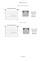
RS-232 Adaptors
RJ45-to-DB25M
RJ45-to-DB9F
DB25F-to-DB9M
Page 42 of 52
USR4204 User Guide
RJ45-to-DB9M Null Modem
RJ45-to-DB9M
Page 43 of 52
USR4204 User Guide
Straight and Rollover Cables
Rollover Cable
Straight Cable
Page 44 of 52
USR4204 User Guide
Legal Notice
The information in this publication is subject to change without notice and is provided “AS
IS” WITHOUT WARRANTY OF ANY KIND. THE ENTIRE RISK ARISING OUT OF THE USE OF
THIS INFORMATION REMAINS WITH RECIPIENT. IN NO EVENT SHALL U.S.ROBOTICS BE
LIABLE FOR ANY DIRECT, CONSEQUENTIAL, INCIDENTAL, SPECIAL, PUNITIVE OR OTHER
DAMAGES WHATSOEVER (INCLUDING WITHOUT LIMITATION, DAMAGES FOR LOSS OF
BUSINESS PROFITS, BUSINESS INTERRUPTION OR LOSS OF BUSINESS INFORMATION),
EVEN IF U.S.ROBOTICS HAS BEEN ADVISED OF THE POSSIBILITY OF SUCH DAMAGES.
This publication does not constitute an endorsement of the product or products that were
tested. The configuration or configurations tested or described may or may not be the only
available solution. This test is not a determination or product quality or correctness, nor
does it ensure compliance with any federal state or local requirements.
The safety precautions listed in this user guide must be observed at all times. Failure to
comply with these precautions may result in injury and property damage. U.S. Robotics
assumes no liability for the customer's failure to comply with these requirements.
WARNING!
YOU ARE EXPRESSLY PROHIBITED FROM USING THIS PRODUCT IN HIGH RISK
APPLICATIONS AND SUCH USE SHALL BE AT YOUR SOLE RISK. AS USED IN THIS
PARAGRAPH, “HIGH RISK APPLICATIONS” REFERS TO USAGE IN OR IN
CONJUNCTION WITH EQUIPMENT FOR WHICH FAILURE OF THE USR PRODUCT
MAY RESULT IN PROPERTY DAMAGE, BODILY INJURY, EMOTIONAL INJURY OR
LOSS OF LIFE, INCLUDING BUT NOT LIMITED TO ATOMIC ENERGY CONTROL
EQUIPMENT, AIRCRAFT OR SPACECRAFT EQUIPMENT, TRAFFIC CONTROL
EQUIPMENT, TRANSPORTATION EQUIPMENT, COMBUSTIBLE CONTROL
EQUIPMENT, MEDICAL OR DIAGNOSTIC EQUIPMENT, AND ALL TYPES OF
MANUFACTURING AND SAFETY DEVICES.
Page 45 of 52
USR4204 User Guide
Warranty
U.S. Robotics Corporation Two (2) Year Limited Warranty
1.0 GENERAL TERMS:
1.1 This Limited Warranty is extended only to the original end-user purchaser (CUSTOMER) and is not transferable.
1.2 No agent, reseller, or business partner of U.S. Robotics Corporation (U.S. ROBOTICS) is authorized to modify
the terms of this Limited Warranty on behalf of U.S. ROBOTICS.
1.3 This Limited Warranty expressly excludes any product that has not been purchased as new from U.S.
ROBOTICS or its authorized reseller.
1.4 This Limited Warranty is only applicable in the country or territory where the product is intended for use (As
indicated by the Product Model Number and any local approval stickers affixed to the product).
1.5 U.S. ROBOTICS warrants to the CUSTOMER that this product will be free from defects in workmanship and
materials, under normal use and service, for TWO YEARS from the date of purchase from U.S. ROBOTICS or its
authorized reseller.
1.6 U.S. ROBOTICS’ sole obligation under this Limited Warranty shall be, at U.S. ROBOTICS’ sole discretion, to
repair the defective product or part with new or reconditioned parts; or to exchange the defective product or part
with a new or reconditioned product or part that is the same or similar; or if neither of the two foregoing options is
reasonably available, U.S. ROBOTICS may, at its sole discretion, provide a prorated refund to the CUSTOMER of
the purchase price of the product, as evidenced by the proof of purchase, less any applicable service fees in
accordance with the following schedule:
Months 0- 3:
100%
Months 4 – 12:
50%
Year 1 – 2:
25%
1.7 A product or part that is repaired or replaced under this Limited Warranty shall be covered for the remainder of
the original warranty period applying to the product or part, or for NINETY (90) days, whichever is longer. All
products or parts that are exchanged for replacement will become the property of U.S. ROBOTICS.
1.8 U.S. ROBOTICS makes no warranty or representation that this product will meet CUSTOMER requirements or
work in combination with any hardware or software products provided by third parties.
1.9 U.S. ROBOTICS makes no warranty or representation that the operation of the software products provided with
this product will be uninterrupted or error free, or that all defects in software products will be corrected.
1.10 U.S. ROBOTICS shall not be responsible for any software or other CUSTOMER data or information contained in
or stored on this product.
1.11 U.S. ROBOTICS products are not designed for any “critical applications.” ”Critical applications” shall mean life
support systems, medical applications, connections to implanted medical devices, commercial transportation,
nuclear facilities or systems or any other applications where product failure could lead to injury to persons or loss
of life or property damage.
2.0 CUSTOMER OBLIGATIONS:
2.1 CUSTOMER assumes full responsibility that this product meets CUSTOMER specifications and requirements.
2.2 CUSTOMER is specifically advised to make a backup copy of all software provided with this product.
Page 46 of 52
USR4204 User Guide
2.3 CUSTOMER assumes full responsibility to properly install and configure this product and to ensure proper
installation, configuration, operation and compatibility with the operating environment in which this product is to
function.
2.4 CUSTOMER must furnish U.S. ROBOTICS or its authorized reseller a dated Proof of Purchase (copy of original,
dated purchase receipt from U.S. ROBOTICS or its authorized reseller) for any warranty claims to be authorized.
3.0 OBTAINING WARRANTY SERVICE:
3.1 CUSTOMER must contact U.S. ROBOTICS Technical Support within the applicable warranty period to obtain
warranty service authorization.
3.2 For information on how to contact U.S. ROBOTICS Technical Support please see the U.S. ROBOTICS corporate
Web site at: www.usr.com
3.3 CUSTOMER should have the following information/items readily available when contacting U.S. ROBOTICS
Technical Support:
Product Model Number
Product Serial Number
Dated Proof of Purchase
CUSTOMER contact name & telephone number
CUSTOMER Computer Operating System version
U.S. ROBOTICS Installation CD-ROM
U.S. ROBOTICS Installation Guide
4.0 WARRANTY REPLACEMENT:
4.1 In the event U.S. ROBOTICS Technical Support determines the product or part has a malfunction or failure
attributable directly to faulty workmanship and/or materials; and the product is within the TWO (2) YEAR warranty
term; the CUSTOMER will include a copy of the dated Proof of Purchase (original purchase receipt from U.S.
ROBOTICS or its authorized reseller) with the returned product or part, then U.S. ROBOTICS will issue CUSTOMER
a Return Material Authorization (RMA) and instructions for the return of the product to the authorized U.S.
ROBOTICS Return Center.
4.2 Any product or part returned to U.S. ROBOTICS without an RMA issued by U.S. ROBOTICS prominently
displayed on the exterior of the return packaging will be returned.
4.3 CUSTOMER agrees to pay shipping charges to return the product or part to the authorized U.S. ROBOTICS
Return Center; to insure the product or assume the risk of loss or damage which may occur in transit; and to ship
the product in the original packaging.
4.4 Responsibility for loss or damage does not transfer to U.S. ROBOTICS until the returned product or part is
received as an authorized return at an authorized U.S. ROBOTICS Return Center.
4.5 Authorized CUSTOMER returns will be unpacked, visually inspected, and matched to the Product Model Number
and Product Serial Number for which the RMA was authorized. The enclosed Proof of Purchase will be inspected for
date of purchase and place of purchase. U.S. ROBOTICS may deny warranty service if visual inspection of the
returned product or part does not match the CUSTOMER supplied information for which the RMA was issued.
4.6 U.S. ROBOTICS retains the final decision whether products are within warranty conditions. In the event U.S.
ROBOTICS determines that the product is not within warranty conditions, or is without the original packaging and
accessories, CUSTOMER will not be entitled to repair or a refund and the product will be returned to CUSTOMER.
Page 47 of 52
USR4204 User Guide
4.7 Once a CUSTOMER return has been unpacked, visually inspected, and tested U.S. ROBOTICS will, at its sole
discretion, repair or replace the product, using new or reconditioned product or parts, to whatever extent it deems
necessary to restore the product or part to operating condition.
4.8 U.S. ROBOTICS will make reasonable efforts to ship the repaired or replaced product or part to CUSTOMER, at
U.S. ROBOTICS expense, not later than TWENTY ONE (21) DAYS after U.S. ROBOTICS receives the authorized
CUSTOMER return.
4.9 U.S. ROBOTICS shall not be liable for any damages caused by delay in delivering or furnishing repaired or
replaced product or part.
5.0 LIMITATIONS:
5.1 THIRD-PARTY SOFTWARE: This U.S. ROBOTICS product may include or be bundled with third-party software,
the use of which is governed by separate end-user license agreements provided by third-party software vendors.
This U.S. ROBOTICS Limited Warranty does not apply to such third-party software. For the applicable warranty
refer to the end-user license agreement governing the use of such software.
5.2 UNAUTHORIZED PRODUCTS: To the extent permitted by applicable law, this U.S. ROBOTICS Limited Warranty
does not apply to distressed, “grey market” or liquidated inventory and all such products are sold “as is” without
any warranty. Further, this U.S. ROBOTICS Limited Warranty does not apply and U.S. ROBOTICS assumes no
responsibility or liability for counterfeit products or for products sold by auction or by parties who are not
specifically authorized by U.S. ROBOTICS.
5.3 DAMAGE DUE TO MISUSE, NEGLECT, NON-COMPLIANCE, IMPROPER INSTALLATION, AND/OR ENVIRONMENTAL
FACTORS: To the extent permitted by applicable law, this U.S. ROBOTICS Limited Warranty does not apply to
normal wear and tear; damage or loss of data due to interoperability with current and/or future versions of
operating system or other current and/or future software and hardware; alterations (by persons other than U.S.
ROBOTICS); damage caused by operator error or non-compliance with instructions as set out in the user
documentation or other accompanying documentation; damage caused by acts of nature such as lightning, storms,
floods, fires, and earthquakes, etc. Products evidencing the product serial number has been tampered with or
removed; misuse, neglect, and improper handling; damage caused by undue physical, temperature, or electrical
stress; damage or loss of data caused by a computer virus, worm, Trojan horse, or memory content corruption;
failures of the product which result from accident, abuse, misuse (including but not limited to improper installation,
connection to incorrect voltages, and power points); electrical transients or disturbances in the line power (mains)
connected to the device or in a telephone network connected to the device, including any transient phenomenon
due to the cross connected nature of a device between these two networks, failures caused by products not
supplied by U.S. ROBOTICS; damage cause by moisture, corrosive environments, high voltage surges, shipping,
abnormal working conditions; or the use of the product outside the borders of the country or territory intended for
use (As indicated by the Product Model Number and any local telecommunication approval stickers affixed to the
product).
5.4 TO THE FULL EXTENT ALLOWED BY LAW, THE FOREGOING WARRANTIES AND REMEDIES ARE EXCLUSIVE AND
ARE IN LIEU OF ALL OTHER WARRANTIES, TERMS, OR CONDITIONS, EXPRESS OR IMPLIED, EITHER IN FACT OR
BY OPERATION OF LAW, STATUTORY OR OTHERWISE, INCLUDING WARRANTIES, TERMS, OR CONDITIONS OF
MERCHANTABILITY, FITNESS FOR A PARTICULAR PURPOSE, SATISFACTORY QUALITY, CORRESPONDENCE WITH
DESCRIPTION, AND NON-INFRINGEMENT, ALL OF WHICH ARE EXPRESSLY DISCLAIMED. U.S. ROBOTICS NEITHER
ASSUMES NOR AUTHORIZES ANY OTHER PERSON TO ASSUME FOR IT ANY OTHER LIABILITY IN CONNECTION
WITH THE SALE, INSTALLATION, MAINTENANCE, WARRANTY, OR USE OF ITS PRODUCTS.
5.5 LIMITATION OF LIABILITY. TO THE FULL EXTENT ALLOWED BY LAW, U.S. ROBOTICS ALSO EXCLUDES FOR
ITSELF AND ITS SUPPLIERS ANY LIABILITY, WHETHER BASED IN CONTRACT OR TORT (INCLUDING NEGLIGENCE),
FOR INCIDENTAL, CONSEQUENTIAL, INDIRECT, SPECIAL, OR PUNITIVE DAMAGES OF ANY KIND, OR FOR LOSS OF
REVENUE OR PROFITS, LOSS OF BUSINESS, LOSS OF INFORMATION OR DATA, OR OTHER FINANCIAL LOSS
ARISING OUT OF OR IN CONNECTION WITH THE SALE, INSTALLATION, MAINTENANCE, USE, PERFORMANCE,
FAILURE, OR INTERRUPTION OF ITS PRODUCTS, EVEN IF U.S. ROBOTICS OR ITS AUTHORIZED RESELLER HAS
BEEN ADVISED OF THE POSSIBILITY OF SUCH DAMAGES, AND LIMITS ITS LIABILITY TO REPAIR, REPLACEMENT,
Page 48 of 52
USR4204 User Guide
OR REFUND OF THE PURCHASE PRICE PAID, AT U.S. ROBOTICS OPTION. THIS DISCLAIMER OF LIABILITY FOR
DAMAGES WILL NOT BE AFFECTED IF ANY REMEDY PROVIDED HEREIN SHALL FAIL OF ITS ESSENTIAL PURPOSE.
6.0 STATUTORY RIGHTS OF CUSTOMER:
Some countries, states, territories or provinces do not allow the exclusion or limitation of implied warranties or the
limitation of incidental or consequential damages for certain products supplied to consumers or the limitation of
liability for personal injury, so the above limitations and exclusions may be limited in their application to
CUSTOMER. When the implied warranties are not allowed by law to be excluded in their entirety, they will be
limited in scope and duration to this written Limited Warranty. This Limited Warranty gives CUSTOMER specific
legal rights. CUSTOMER may also have other rights that may vary from state to state or from country to country.
CUSTOMER is advised to consult applicable state or country laws for full determination of its rights. If any term is
held to be illegal or unenforceable, the legality or enforceability of the remaining terms shall not be affected or
impaired.
7.0 GOVERNING LAW:
This Limited Warranty shall be governed by the laws of the State of Illinois, U.S.A. excluding its conflicts of laws
principles and excluding the United Nations Convention on Contracts for the International Sale of Goods.
U.S. Robotics Corporation
1300 East Woodfield Road, Suite 506
Schaumburg, IL, 60173
U.S.A.
Page 49 of 52
USR4204 User Guide
Regulatory Information
FCC Compliance
D e c l a r a t i o n of C o n f or m i t y
U.S. Robotics Corporation
1300 E. Woodfield Rd. Suite 506
Schaumburg, IL 60173
U.S.A.
declares that this product conforms to the FCC’s specifications:
Part 15, Class A
This equipment complies with Part 15, Class A for use in a commercial, industrial, or business
environment.
Note: This equipment has been tested and found to comply with the limits for a Class A digital device,
pursuant to part 15 of the FCC Rules. These limits are designed to provide reasonable protection
against harmful interference when the equipment is operated in a commercial environment. This
equipment generates, uses, and can radiate radio frequency energy and, if not installed and used in
accordance with the instruction manual, may cause harmful interference to radio communications.
Operation of this equipment in a residential area is likely to cause harmful interference in which case
the user will be required to correct the interference at one’s own expense.
Modifications not expressly approved by the manufacturer could void the user's authority to operate
the equipment under FCC rules.
UL Listing/CUL Listing
This information technology equipment is UL Listed and C-UL Listed for both the US
and Canadian markets respectively for the uses described in this User Guide. Use
this product only with UL Listed Information Technology Equipment (ITE).
Industry Canada (IC)
This digital apparatus does not exceed the Class A limits for radio noise emissions from digital
apparatus set out in the interference-causing equipment standard entitled Digital Apparatus, ICES-003
of Industry Canada.
Customer Information
Notice: This equipment meets the applicable Industry Canada Terminal Equipment Technical
Specifications. This is confirmed by the registration number. The abbreviation, IC, before
the registration number signifies that registration was performed based on a Declaration of
Conformity indicating that Industry Canada technical specifications were met. It does not
imply that Industry Canada approved the equipment.
Page 50 of 52
USR4204 User Guide
CE Compliance
D e c l a r a t i o n of C o n f or m i t y
We, U.S. Robotics Corporation of 1300 E. Woodfield Rd. Suite 506, Schaumburg, Illinois, 60173-5446
USA, declare under our sole responsibility that the product, USRobotics model USR4204, to which this
declaration relates, is in conformity with the following standards and/or other normative documents.
EN60950-1
EN55022
EN55024
EN61000-3-2
EN61000-3-3
We hereby declare that the above named product is in conformity with the essential requirements and
other relevant provisions of Directive 2011/65/EU.
The conformity assessment procedure referred to in Article 10(3) and detailed in Annex IV of Directive
1999/5/EC has been followed.
An electronic copy of the original CE Declaration of Conformity is available at the U.S. Robotics
website: www.usr.com
WEEE Compliance
CONSUMER NOTICE
For the following Countries:
Austria
Estonia
Iceland
Netherlands
Slovenia
Belgium
Finland
Ireland
Norway
Spain
Croatia
France
Italy
Poland
Sweden
Cyprus
Germany
Latvia
Portugal
Switzerland
Czech Republic
Greece
Luxemburg
Romania
Turkey
Denmark
Hungary
Malta
Slovakia
United Kingdom
This product is subject to Directive 2002/96/EC of the European Parliament and the Council
of the European Union on waste electrical and electronic equipment (WEEE) and, in
jurisdictions adopting that Directive, is marked as being put on the market after August 13,
2005 and should not be disposed of as unsorted municipal waste. Please utilize your local
WEEE collection facilities in the disposition of this product and otherwise observe all
applicable requirements. For further information on the requirements regarding the
disposition of this product and collection facilities that maybe available to you, please visit
www.usr.com/weee.
Page 51 of 52
USR4204 User Guide
Copyright Information
U.S. Robotics Corporation
1300 E. Woodfield Road, Suite 506
Schaumburg, Illinois
60173-5446
USA
No part of this documentation may be reproduced in any form or by any means or used to
make any derivative work (such as a translation, transformation, or adaptation) without
written permission from U.S. Robotics Corporation. U.S. Robotics Corporation reserves the
right to revise this documentation and to make changes in the products and/or content of
this document from time to time without obligation to provide notification of such revision or
change. U.S. Robotics Corporation provides this documentation without warranty of any
kind, implied or expressed, including, but not limited to, implied warranties of
merchantability and fitness for a particular purpose. If there is any software on removable
media described in this documentation, it is furnished under a license agreement included
with the product as a separate document, in the hard copy documentation, or on the
removable media in a directory named LICENSE. If you are unable to locate a copy, please
contact U.S. Robotics and a copy will be provided to you.
UNITED STATES GOVERNMENT LEGEND If you are a United States government agency,
then this documentation and the software described herein are provided to you subject to
the following:
All technical data and computer software are commercial in nature and developed solely at
private expense. Software is delivered as “Commercial Computer Software” as defined in
DFARS 252.227-7014 (June 1995) or as a “commercial item” as defined in FAR 2.101(a)
and as such is provided with only such rights as are provided in U.S. Robotics standard
commercial license for the Software. Technical data is provided with limited rights only as
provided in DFAR 252.227-7015 (Nov 1995) or FAR 52.227-14 (June 1987) whichever is
applicable. You agree not to remove or deface any portion of any legend provided on any
licensed program or documentation contained in, or delivered to you in conjunction with,
this User Guide.
Copyright © 2012 U.S. Robotics Corporation. All rights reserved. U.S. Robotics and the U.S.
Robotics logo are registered trademarks of U.S. Robotics Corporation. Other product names
are for identification purposes only and may be trademarks of their respective companies.
Product specifications are subject to change without notice.
Page 52 of 52