1
SuperScript 100C Online User’s Guide
COPYRIGHT = Copyright 1996, NEC Technologies
All rights reserved
Publication issued by:
NEC Technologies, Inc.
339 North Bernardo Avenue
Mountain View, CA 94043
NEC Technologies reserves the right to modify the equipment described in this
manual at any time and without notice.
NEC Technologies, Inc.
305 Foster Street Littleton MA 01460-2004 Tel: (508) 742-8000
NECTECH SOFTWARE LICENSE AGREEMENT
PLEASE CAREFULLY READ THE FOLLOWING TERMS AND CONDITIONS BEFORE OPENING THIS
SOFTWARE PACKAGE: OPENING THE PACKAGE INDICATES THAT YOU HAVE ACCEPTED THESE TERMS
AND CONDITIONS. IF YOU DO NOT AGREE WITH THEM, YOU SHOULD IMMEDIATELY RETURN THE
PACKAGE UNOPENED AND THE PRODUCT UNUSED TO THE PERSON FROM WHOM YOU PURCHASED THE
PACKAGE WITHIN A REASONABLE PERIOD OF TIME FOR A FULL REFUND OF MONEY PAID FOR THE
PACKAGE.
NECTECH provides the Software and licenses its use to you, the licensee, pursuant
to the following terms. (From this time on, references to you mean the licensee,
references to NECTECH mean NEC Technologies, Inc., references to Adobe mean Adobe
Systems Incorporated, a California corporation located at 1585 Charlestone Road,
Mountain View, California 94039-7900, U.S.A., references to the Printer mean the
printer product purchased with the Software, and references to the Software mean
the software programs, including the coded font programs, in the medium (e.g.,
floppy disk, CD-ROM) of this package and/or in the ROM of the Printer and any
other enhancements to the Software which you hereafter may acquire from NECTECH
unless such acquisition is subject to another written license agreement.)
You assume responsibility for the selection of the Software to achieve your
intended results. Further, you are responsible for the installation, use and
results obtained from the Software.
LICENSE
1. (NECTECH grants to you a nonexclusive and royalty-fee license, subject to these
sections (1) through (5) and the other provisions hereof:
•
•
•
to use on the Printer one (1) copy of that portion of the Software which is
provided to you preinstalled in the ROM of the Printer;
to use on up to five (5) computers connected to the printer that portion of the
Software included in the medium of this package; and
to use the typeface trademarks used by NECTECH to identify the coded font
programs and typefaces produced therefrom, provided that you can only use such
trademarks to identify printed output produced by the coded font programs.
You may not rent or lease the Software, but you may transfer the Printer, the
Software and accompanying documentation on a permanent basis, provided that you
retain no copies of the Software and the recipient agrees to be bound by all of
the terms and conditions of this Agreement.
2. You agree not to alter, reverse engineer or disassemble the Software. You will
not copy
the Software except as necessary to use them on computers and the
Printer described in section (1) above or backup purposes. You agree that any
such copies of the Software shall contain the same proprietary notices that
appear on and in the Software.
3. Title to and ownership of the Software, related documentation and any
reproduction thereof shall remain with NECTECH and its suppliers and the
trademarks are the property of such trademark owners. Except as stated in
section (1) and (2) above, this Agreement does not grant to you any right
(whenever by license, ownership or otherwise) in or to patents, copyrights,
trade secrets, trade names, trademarks or any other intellectual property right
with respect to the Software.
4. You will not export or re-export the Software without the appropriate United
States or foreign government licenses.
5. You are hereby notified that Adobe is a third-party beneficiary to this
Agreement to the extent that this Agreement contains provisions which relate to
your use of the Software. Such provisions are made expressly for the benefit of
adobe and are enforceable by Adobe in addition to NECTECH.
COPYRIGHT
THE SOFTWARE IS COPYRIGHTED AND, EXCEPT AS PERMITTED BY THIS AGREEMENT,
YOU MAY NOT DUPLICATE THE SOFTWARE OR DISCLOSE IT TO ANY OTHER PARTY.
TERM
This Agreement is effective until terminated. You may terminate it voluntarily at
any time. Voluntary termination by you must be accompanied by complete destruction
of the Software and copies thereof. NECTECH or its suppliers may terminate this
Agreement without notice upon your failure to abide by this Agreement.
LIMITED WARRANTY
1. NECTECH warrants to you that each medium (floppy disk, ROM and/or CD-ROM)
containing the Software is free from defects in materials and workmanship and
also warrants that it will replace any defective medium at no charge to you, if
any such defective medium is returned to NECTECH within ninety (90) days of
your purchase. (Any such return should be made to NECTECH at the address on
this Agreement. Attention: printer Software Marketing<170>, together with a
written notification of the defect.)
2. YOU AGREE THAT THE SOFTWARE IS PROVIDED AND LICENSED AS IS. TO THE MAXIMUM
EXTENT PERMITTED BY APPLICABLE LAW, NECTECH AND ITS SUPPLIERS DISCLAIM ALL
OTHER WARRANTIES, EITHER EXPRESS OR IMPLIED, INCLUDING, BUT NOT LIMITED TO,
IMPLIED WARRANTIES OF MERCHANTABILITY AND FITNESS FOR A PARTICULAR PURPOSE,
WITH REGARD TO THE SOFTWARE. YOU BEAR THE ENTIRE RISK RELATING TO THE QUALITY
OF THE SOFTWARE AND, IF THE SOFTWARE PROVES TO HAVE ANY DEFECTS, YOU ASSUME THE
COST OF ANY NECESSARY SERVICING OR REPAIRS.
3. SOME STATES DO NOT ALLOW THE EXCLUSION OF IMPLIED WARRANTIES, SO THAT THE ABOVE
EXTENSION MAY NOT APPLY TO YOU. THIS WARRANTY GIVES YOU SPECIAL LEGAL RIGHTS
AND YOU MAY ALSO HAVE OTHER RIGHTS WHICH VARY FROM STATE TO STATE.
LIABILITY
TO THE MAXIMUM EXTENT PERMITTED BY APPLICABLE LAW, IN NO EVENT SHALL NECTECH OR
ITS SUPPLIERS BE LIABLE FOR ANY DAMAGES WHATSOEVER (INCLUDING, WITHOUT LIMITATION,
LOSS OF USE, LOSS OF PROFIT, INTERRUPTION OF BUSINESS, OR ANY INDIRECT, SPECIAL,
INCIDENTAL OR CONSEQUENTIAL DAMAGES OF ANY KIND) REGARDLESS OF THE FORM OF ACTION
WHETHER IN CONTRACT, TORT (INCLUDING NEGLIGENCE), STRICT PRODUCT LIABILITY OR
OTHERWISE, EVEN IF NECTECH
HAS BEEN ADVISED OF THE POSSIBILITY OF SUCH DAMAGES. BECAUSE SOME STATES DO NOT
ALLOW THE EXCLUSION OR LIMITATION OF LIABILITY FOR INCIDENTAL OR CONSEQUENTIAL
DAMAGES, THE ABOVE LIMITATIONS MAY NOT APPLY TO YOU.
THIS AGREEMENT SHALL BE CONSTRUED AND INTERPRETED ACCORDING TO THE LAWS OF THE
COMMONWEALTH OF MASSACHUSETTS.
Preface
This non-impact printer is designed and constructed to give constant print quality
for text and high resolution graphics, in color and in black and white.
The printer has a disposable print head, containing water-resistant
ink, which uses "drop-on-demand" thermal ink jet technology. It produces a laserlike print density of up to 600 x 300 dots per inch (dpi) with minimal operating
disturbance. The standard paper handling device allows the use of a wide range of
paper and envelope types and sizes.
The printer can be connected to personal computers with a standard
Centronics parallel interface. The resident firmware contains two emulation's: PCL
III + and IBM<N>Proprinter X24 4207/1. Compatible with MS-DOS and MS-Windows
environments, as well as other commonly-used software applications, it can be used
in most Word Processing and Desk-Top Publishing environments.
The Structure of the Manual
This user manual is divided into two parts: a Quick Start, which contains the
essential information for installing and operating the printer, and a User Guide,
divided into chapters, which contains more detailed information on the printer's
features and functions. The manual also contains a glossary of terms and an
alphabetical index.
Quick Start
•
Unpacking
•
Identifying the printer parts
•
Connecting your printer
•
Inserting the print head
•
Loading paper
•
Printing the "demo" page
•
Installing printer software
•
Help
User Guide
Chapter 1 - User Interface
Embossed template, containing common error conditions and print head
insertion procedure. Operator panel, giving the functions of the light
indicators (LED's) and keys.
Chapter 2 - Ink Jet Print Head
How to insert/remove the ink jet print head in/from the printer, how to
clean it and preserve optimum print quality. How to obtain the "demo" page.
Chapter 3 - Paper
Characteristics of the paper that can be used in the printer.
Chapter 4 - Using Software
How to change the printer settings via the printer driver settings or the
printer set-up utility.
Chapter 5 - Troubleshooting
Troubleshooting guide, indicating common problems and their solution.
Appendices
Options and product characteristics.
Refer to the appropriate chapter of the user guide whenever you encounter a
problem.
QUICK START
This section is a rapid guide for installing your printer and preparing it for
use. It contains a sequence of operations which should be performed in the order
prescribed.
•
Unpacking
2
•
Identifying the printer parts
3
•
Connecting your printer
4
•
Inserting the print head
5
•
Loading paper
7
•
Printing the "demo" page
9
•
Installing printer software
10
•
Help!
12
More detailed information about the printer and its functions is given in the User
Guide.
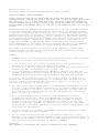
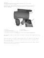
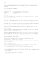
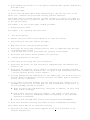
Unpacking
Keep the carton and all the packing materials in case you have
to repack or ship the printer.
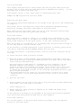
As soon as you have removed the printer and its accessories from the
packing carton, check that all the parts ordered have been delivered
and are undamaged.
1
4
3
5
2
1. Printer
2. Ink jet print head
5. Garage for storing print head
3. User manual
4. Driver diskette(s)
If anything is missing or damaged, call your local retailer immediately.
The interface cable for connecting the printer to your PC is NOT supplied with the
printer.
Place the printer on an ample, stable surface near your computer or work station.
Make sure that there is enough space around the printer for all its parts to be
accessed comfortably.
Make sure that there is a convenient independent electrical power supply socket to
which you can connect the printer.
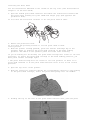
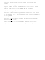
Identifying the Printer Parts
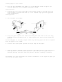
Connecting Your Printer
To the electrical power supply
Your printer has no ON-OFF switch and is powered as soon as you connect it to the
electrical power supply, so make sure that it is on a stable surface and that the
top cover is closed. After approximately 2 minutes of inactivity, the printer
will go into "standby" mode in which both light indicators are off and the print
head is
in its rest position at the left hand end of its path.
Make sure the power supplied has the voltage indicated on the electrical data
plate on the base of the printer. If the electrical data plate indicates a
different voltage, call your local retailer immediately. DO NOT, UNDER ANY
CIRCUMSTANCES, CONNECT THE PRINTER TO THE ELECTRICAL POWER SUPPLY.
Make sure that the plug on the power cable of the printer is of the type
accepted by the wall socket you intend to use; if it is not, call your local
retailer.
Do NOT attempt to change the plug yourself.
The manufacturer declines all responsibility for accidents to persons or damage
to the printer arising from the non-observance of this warning.
•
Plug the printer power cable into a wall socket.
The socket outlet shall be installed near the equipment and shall be easily
accessible.
The printer will execute a series of internal checks and a mechanical reset.
will be in ON LINE condition (On Line LED lit).
It
To your computer
Make sure your printer is NOT connected to the electrical power
supply and that your computer/host system is switched OFF.
•
Plug the interface cable connector into the socket on the rear of the printer
and, if
necessary, close the spring clips on it.
•
Connect the other end of the interface cable to the appropriate interface
connector socket (port) on your computer/host system.
•
Connect your printer to the electrical power supply and switch on your
computer.
The interface cable is not supplied with the printer; consult your systems
engineer or retailer for advice on the type of cable you require. A manufacturerrecommended interface cable is available as an option.
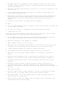
Inserting the Print Head
See the instructions embossed on the inside of the top cover (and illustrated in
Chapter 1 of the User Guide)
•
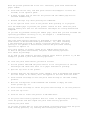
Open the sealed print head container and remove the instructions leaflet and
the print head, holding it by the thumb and finger grip (end opposite the
protective film).
Do not touch the electrical contacts or sit the print head on them.
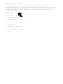
• Remove the protective film.
Do not touch the printing nozzles or sit the print head on them.
Insert picture
• With the printer already powered, press the Install Cartridge key on the
operator panel to position the print head carriage in the head loading
position. The LED's on the operator panel will both start flashing.
If you do nothing for 60 seconds, the print head carriage will return to its rest
position*. To return the print head carriage to the head loading position, you
must press Install Cartridge again.
* The print head carriage will not return to its rest position if there is no
print head inserted or if the print head selection lever is not in the correct
position.
•
Open the top cover of the printer.
•
With the electrical contacts towards the corresponding contacts in the housing
on the print head carriage, insert the print head gently into its chamber.
•
Holding the lip at the rear of the print head insertion area, push the print
head towards the rear of the printer to fix it in place.
•
Check that the position of the print head selection lever, to the left of the
ASF, is compatible with the type of print head you have inserted.
The lever positions are marked on the printer casing in front of the lever:
The lever must NOT be forced and must be moved ONLY when the print head carriage
is in the loading position.
•
Press the Install Cartridge key on the operator panel. The print head carriage
will move to the print head rest position, at the left hand side of the
printer.
•
Close the top cover
See Chapter 2 in the User Guide for further details on the handling and care of
the ink jet print head.
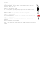
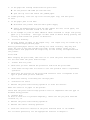
Loading Paper in the Printer
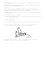
•
Pull out the extendible top guide (1) on the ASF and rotate it up to its
vertical position (2), to support the paper loaded.
Insert picture
•
Holding the tab on the right edge of the movable guide on the ASF, pull the
guide slightly forwards and move it to its extreme right position (physical
right hand margin).
Insert picture
•
Fan the paper thoroughly.
•
Align the paper against the fixed left hand guide and load it into the tray,
pushing it down carefully until it stops against the feed rollers inside the
printer.
Do NOT add paper to the ASF; always remove any existing paper and fan it together
with the paper to be loaded.
•
Position the right guide against the right edge of the paper.
•
With the printer powered, press Form Feed. The paper moves to the Top of Form
(TOF) position. Press Form Feed again, to make sure that the paper feeds
smoothly through and exits from the printer, without crushing or skewing.
See Chapter 3 in the User Guide for further information on the types of paper you
can use and the page layout.
Printing the "Demo" Page
With the printer powered, print head installed and paper loaded:
•
Press and hold the On Line key, and press the Install Cartridge key (for at
least 2 seconds) on the operator panel.
•
A sheet of paper will be fed into the printer and the "demo" page will be
executed automatically.
•
Release the keys only after printing has commenced.
Do not open the front cover of the printer while printing is in progress.
Once the "demo" page is printed, the printer returns On Line.
To print another "demo" page, press and hold On Line and then press Install
Cartridge (for at least 2 seconds).
To suspend printing temporarily, press On Line (pressing this key a second time
will cause printing to continue).
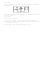
The "demo" page lists the principal features of your printer and contains a nozzle
test that gives a graphic representation of the functioning of the print head.
The "demo" page contents may vary with respect to that illustrated here, but this
will not affect the functioning of your printer in any way.
If you have inserted a color print head, the same key sequence will cause the same
"demo" page to be printed in color.
-
Installing Printer Software
The diskette supplied with your printer contains the SuperScript™
quality color printer driver.
100C high
For Windows® users: to work in Windows® 3.1/3.11 or Windows® 95 environment, you
MUST first install the driver. This driver gives you access to all the printer
features.
For DOS users: please refer to the chapter "Using Software" in the User Guide.
The contents of the diskettes guarantee compatibility with the specific operating
environments and provide a user-friendly interface for programming the printer.
The diskettes have a "Read-Me" file and requirements and last minute information
on your driver. This file should be read BEFORE installing your driver (for
Windows® 3.1/3.11 users, open the file through the "Write" application; for
Windows® 95 users, through "WordPad" specifying the file name README.WRI).
Before installing any printer driver, we
the original diskettes and then use this
This will allow you to keep the original
problem arise with the back-up copy, you
recommend that you make a back-up copy of
copy for the installation procedure.
diskettes as masters so that, should any
can make another copy.
Installing the SuperScript 100C color printer driver
System requirements:
•
Windows 3.1 or later,
•
PC 386 or later with at least 2 MEGA Bytes of RAM,
•
1 MEGA Bytes of free disk space.
Installation procedure in Windows® 3.1/3.11 environment
To choose the driver language you require and then install the driver, proceed as
follows:
1) Insert the specific diskette in drive A of your PC.
2) Activate Windows® environment (if necessary, consult your Windows® user
manual).
3) Now activate the Control Panel in the Main group, clicking twice with your
mouse indicator on the corresponding icon.
4) Select the Printers icon, in the same way.
5) If the Installed Printers box is empty, click on Install..
6) If the Installed Printers box already contains one or more driver names, click
on Add, select Install Unlisted or Updated Printer in the List of Printers and
then click on Install… .
7) Check that the Install Driver window already indicates the drive (usually A) in
which you have inserted the driver diskette, otherwise, click on the drive name
and change it, using your PC keyboard.
8) Click on OK to display the driver name.
9) The Install Driver window will now show the driver you have selected; click on.
10)The Add Unlisted or Updated Printer window contains the list of drivers present
on
the diskette. Select the driver with your printer name and click on OK.
11)Your driver is now installed and your printer name appears in the List of
Printers.
12)With your printer name highlighted, click on the Set as Default Printer button,
so
that your printer will be active in all your Windows® applications.
13)Check your printer connection by clicking on the Connect.. button. By default,
your
printer will be connected on the LPT1 port which corresponds to the hardware
connection of a parallel interface cable.
14)Click on the Close button of the Printers dialogue box.
For further information, consult your Windows® 3.1/3.11 documentation.
Installation procedure in Windows® 95 environment
To install the driver using the Plug and Play feature, proceed as follows:
Your printer must be powered, connected to your PC and NOT in error mode (no LED's
Flashing).
1) Insert the diskette in drive A of your PC.
2) Activate Windows® 95; if already active, execute the "shut down" command and
select restart (if necessary, consult your Windows® user manual).
3) A window, indicating that a new peripheral has been detected (New hardware
found and the printer name), is displayed.
The same window shows the Driver from disk provided by hardware manufacturer
option
already highlighted. Click on the OK button.
4) With the Install from Disk window displayed, insert the specific driver
diskette in the drive selected, specify this drive and click on OK.
5) Your printer name is displayed in the Select Device window. Click on OK.
6) The Add Printer Wizard window is displayed. If there are no printer drivers
already installed on your system, your printer will be installed as the Default
printer. If other drivers are already installed, you will be asked if you want
to use this printer as the default. Click on Yes.
7) Click on Next. The same window will prompt you to print a Test Page. Click on
Yes, if you want to be sure that the driver has been installed correctly. This
page also gives you a list of all the files that have been copied into your
system during installation.
8) Your driver is now installed. A window will ask you if the test page has been
completed. An affirmative reply indicates that the driver is installed
correctly.
For further information, consult your Windows® 95 documentation.
See Chapter 4 in the User Guide for more details on the drivers and printer
setup.
Help!
To simplify the use of the printer, and to help you if you have problems, this
printer has a template containing a series of operating instructions embossed on
the inside of the front cover. The flashing of the two light indicators (LED's)
signals the need for operator intervention. Should this occur, proceed as
follows:
•
Open the top cover of the printer.
•
Check the position of the print head carriage, which will correspond to one of
the four action items on the template:
1) Check paper,
2) Change color/black switch position,
3) Change ink cartridge,
4) Change print head.
Action items 2, 3 and 4 are illustrated on the template.
For full details, see the section entitled "Embossed Template" in Chapter 1 of the
User Guide.
If you have problems with any operating procedure, or are unable to perform a
specific function, always check that you have followed the instructions as given.
If a repetition of the instructions is unsuccessful, see the section entitled
"Problems and Solutions" in Chapter 5 of the User Guide.
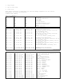
Table of contents
1. User Interface
Embossed Template
Error Conditions and corrective
Print head replacement.
Print head adjustment
Operator Panel
Basic key functions
Special key functions
Light indicator (LED) functions
2.
Ink Jet Print Head
Replacing the Print Head
Print head removal
Print head insertion
Using a Color Print Head
Print Head Care
Printing the "demo" page
Clearing the print head nozzles
Cleaning the print head
5. Troubleshooting
General Care
Error Conditions indicated By Print Head
Position
Problems and Solutions
Installation
Paper
Print Head
Printing
1-1
1-1
1-2
1-2
1-3
1-3
1-4
1-4
2-1
2-2
2-3
2-3
2-4
2-5
2-5
2-6
5-2
5-2
5-3
5-3
5-4
5-6
5-8
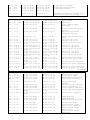
3. Paper
Types
Dimensions
Insertion
Automatic Feed
Semi-automatic feed
Envelopes
Print Area
Single sheets
Envelopes
3-1
3-2
3-2
3-2
3-2
3-3
3-4
3-4
3-5
4. Using Software
Modifying the Settings in Your
Printer
DOS Environment
Running the Printer Set-Up
Utility
4-2
4-4
4-5
Appendices
A. Supplies and Optional Items
B. Printer Settings
C. Command Codes
D. Product Characteristics
E. Getting Service and Support
G. Glossary
Index
User Interface
Embossed Template
On the inside of the top cover of the printer, there is an embossed template. This
template illustrates the operating procedure for changing the print head and how
to adjust the print head position if you wish to print on envelopes. It also
indicates four error conditions.
Error conditions and corrective action
The four error conditions are:
1. CHECK PAPER
There is no paper in the ASF, or there is a paper jam. See Chapter 3 for the
paper
loading procedure and Chapter 5 for information on how to clear paper jams.
2. CHANGE BLACK/COLOR SWITCH POSITION
The position of the print head selection lever is not compatible with the type
of
print head you have inserted. See Chapter 2 for information on the use of the
print
head selection lever.
3. CHANGE INK CARTRIDGE
The print head (ink cartridge) requires replacing.
See Chapter 2 - Replacing the Print Head.
4. CHANGE PRINT HEAD
There is no print head in the printer, the type of print head you have inserted
is not
compatible with the printer driver selected, or the Install Cartridge key has
been
pressed. See Chapter 4 for information on monochrome/color printer drivers.
If one of these error conditions occurs, any printer operation is interrupted, the
On Line and Power LED's start to flash and the print head carriage is positioned
to indicate the action required.
If there is no operator intervention within 60 seconds(with a monochrome print
head inserted) of the error being signaled, the print head carriage returns to its
rest position. To return the print head carriage to the error indication, press
Install Cartridge.
* 30 seconds, if you are using a color print head
** The print head carriage will not return to its rest position if there is no
print head inserted or if the print head selection lever is not in the correct
position.
Once you have corrected the error condition, press Install Cartridge to return the
print head carriage to its rest position, so that the printer can resume
operating.
Further information regarding these and other types of operating errors is
available in Chapter 5 - Troubleshooting.
Print head replacement
This part of the template illustrates the print head/ink cartridge replacement
procedure. It is complementary to the description in the corresponding sections in
Chapter 2.
Print head adjustment
This part of the template illustrates the adjustment switch, depending on the type
of document you are using
Operator Panel
This section describes the functions of the keys and light indicators (LED's) on
the operator panel.
The behavior of the keys and light indicators on the operator panel will depend on
the printer's status:
Printer states:
•
free: no data to be printed;
•
busy: from the reception of data until the completion of its printing;
•
standby: printer powered but dormant (more than two minutes have elapsed since
last interchange with host).
•
special function mode : operating mode independent of host.
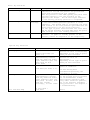
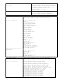
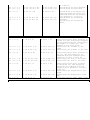
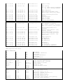
Basic key functions
Function
Printer ready/Pause
Key
On Line
Print head positioning
Install
Cartridge
Paper load/ eject
Form Feed
Description
When the printer is ON LINE, the On Line light
indicator is lit and the printer can process and
print data received from your computer.
When the printer is OFF LINE (pause),the print head
carriage returns to its rest position at the
physical left margin. The On Line light indicator
is off and any printing operation is suspended.
The first time it is pressed, the print head moves
to the head loading position (position 4 of the
template). The second time it is pressed, the print
head returns to its rest position (provided that the
print head lever is in the correct position
for the type of print head inserted. The lever must
NOT be forced and must be moved ONLY when the print
head carriage is in the loading position).
Loads a sheet of paper to the Top of Form (TOF)
position. If paper is already present in the
printer, causes its expulsion to the output tray.
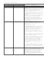
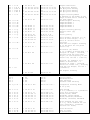
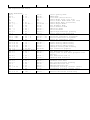
Special key functions
Function
"Demo" page
Print test
Reset
Hex dump
Exit from Hex dump
Key(s)
On Line held
+
Install Cartridge (at
least 2 s)
Press all three keys
simultaneously release
them only when the Power
light indicator goes off,
then press On Line
three times
On Line held
+
Form Feed (at least 3 s)
Press all three keys
simultaneously; release
them only when the Power
light indicator goes off.
then press On Line, Form
Feed and Install
Cartridge,, in this order.
On Line held +
Form Feed
Description
The "demo" page is printed. It
will be in color or monochrome,
depending on the type of print
head you have inserted.
The print test is printed. It
will be in color or
monochrome,,
depending on the type of print
head you have inserted.
Returns the printer to its
power on condition.
If done during data
transmission/printing, the
information is lost.
All subsequent data transmitted
to the printer will be printed
in its hexadecimal format.
This feature should be used
only under technical guidance,
as it can generate extremely
long print-outs. See Chapter 5
- Troubleshooting.
Reset
Light indicator (LED) functions
LED's
ON Line
Lit
Off
flashing slowly
Power
Lit
Lit
flashing slowly
Indication
The printer is powered and ON LINE.
The printer is powered and OFF LINE.
An error condition has occurred in the
printer.
Open the top cover of the printer to check
the print head carriage position with
respect to the action items embossed on the
inside of the front cover.
If the print head carriage indicates 1 CHECK
PAPER there is no paper in the ASF or there
is a paper jam.
Load paper, or a document or an envelope, in
the ASF, or remove the jammed document.
flashing slowly
flashing slowly
If the print head carriage indicates 2
CHANGE COLOR/ BLACK SWITCH POSITION, the
position of the print head selection lever
is not compatible with the type of print
head inserted.
Correct the position of the lever.
If the print head carriage indicates 3
CHANGE INK CARTRIDGE, an "ink cartridge
empty" ("end of ink") condition has
occurred.
Replace the print head.
If the print head carriage indicates 4
CHANGE PRINT HEAD, there is no print head in
the printer, the print head inserted is
not compatible with the driver selected, or
the Install Cartridge key has been
pressed.
Insert a print head, exchange the type of
print head inserted, or replace the print
head.
After correcting the error condition, press
Install Cartridge to return the print head
carriage to its rest position.
If there is no operator intervention within
60 seconds *(with a monochrome print head
inserted; *30 seconds if a color print
head is inserted) of the error being
signaled, the print head carriage will
return to its rest position **. To reread
the error indication,, press Install
Cartridge
** The print head carriage will not return
to its rest position if there is no print
head inserted or if the print head selection
lever is not in the correct position.
flashing rapidly
flashing rapidly
Failure condition.
Disconnect the printer from the power
supply. Make sure the print head carriage
and paper feed paths are not obstructed and
then reconnect the printer to the mains
power supply. If the light indicators
continue flashing rapidly, disconnect the
printer and call the technical assistance
service or your dealer.
off
off
a) The printer is in standby mode (dormant),
i.e. within the last two minutes, there
has been no printer-host interaction nor
operator action.
To return the printer to its operating
condition, just press a key or send a
file to be printed.
b) The printer is in the special functions
mode, awaiting a key sequence activate a
specific function.
Ink Jet Print Head
This chapter describes how to insert/remove the ink jet print head n/from the
printer, how to clean the print head and preserve optimum print quality. It also
describes how to obtain the print test.
Your printer can use a color print head or a monochrome print head.
ALWAYS use NEC-original Ink Jet Print Heads.
Replacing the Print Head
See also the instructions embossed on the inside of the top cover, and illustrated
in Chapter 1.
The printer has an "ink detection" sensor which guarantees optimum printing
quality by allowing the timely replacement of the print head.
When replacing the print head, take care not to touch the print head carriage
shaft nor the area under the print head carriage.
Print head removal
The print head is removed to replace it, to change from a monochrome to color
print head or vice versa, or to repeat its insertion (see the section entitled
"Print head insertion" in the Quick Start), in the case of faulty printing.
When the printer is not powered or is in standby mode, the print head carriage is
in its rest position (at the extreme left).
If the printer is already powered and a print operation is running, press the On
Line key to interrupt printing BEFORE opening the top cover.
To return the printer to operating status, close the top cover and press the On
Line key.
To remove the print head, proceed as follows:
•
With the printer already powered, press <B><N>Install Cartridge to move the
print head carriage to the head loading position (the Power and On Line LED's
start flashing simultaneously).
The print head carriage moves to correspond to error condition 4 on the
embossed template (see Chapter 1) and both LED's start flashing. This
position is held for 60 seconds (30 seconds if the printer has a color print
head), after which the print head carriage returns to its rest position *.
To return the print head carriage to the cartridge replacement position, just
press Install Cartridge.
* The print head will not return to its rest position if there is no print
head inserted or if the print head selection lever is not in the correct
position.
•
Open the top cover.
•
Pinch together the two lips on the rear of the print head carriage (behind the
print head). The print head is released.
Insert Image pg 2-2
•
Remove the print head, pulling it upwards by its thumb and finger grip.
Insert image pg 2-2
If the quality of printing is not optimum, do the print head clearing operation
(see the section entitled Print Head Care in this chapter).
Print head insertion
For the description of the print head insertion procedure, see the specific
section in the Quick Start.
If you have problems inserting the print head:
•
Make sure the print head carriage is in the print head loading position.
•
Check that the print head chamber is clean and free of foreign bodies.
•
NEVER force the print head into the chamber.
•
Always remove it completely and repeat the entire insertion operation.
The insertion/removal procedure for a color print head is the same as for the
standard print head, but REMEMBER to position the print head selection lever for a
color print head. The lever must NOT be forced and must be moved ONLY when the
print head carriage is in the loading position.
Using a Color Print Head
The insertion/removal procedure for a color print head is the same as for the
standard print head. Once you have inserted the color print head, you must set the
print head selection lever (to the left of the ASF) to correspond to the color
indication, before pressing Install Cartridge to return the print head to its rest
position.
The lever must NOT be forced and must be moved ONLY when the print head carriage
is in the loading position.
If you do not position the print
head selection lever to
correspond to the type of print
head inserted, the print head
carriage will not return to its
rest position. It will be
positioned to correspond to error
condition 2 (see specific section
in Chapter 1), and the On Line
and Power light indicators will
flash simultaneously.
Print Head Care
Always keep the print heads (ink
cartridges) sealed until they are
to be used.
Do NOT attempt to refill the
print head with ink, as this
damages the print head and the
printer.
Always make sure that the print
head is in its rest position
BEFORE switching off your
computer. When the printer is
powered, the print head will
automatically return to its rest
position and go into standby mode
after approximately two minutes
of inactivity.
Printing the "demo" page
With the printer powered and in PCL III + emulation, print head installed and
paper loaded:
•
Press and hold On Line, and then press Install Cartridge(for at least two
seconds) on the operator panel.
•
A sheet of paper will be fed into the printer and the "demo" page will be
executed automatically.
•
Release the keys only after printing has commenced.
•
Do not open the front cover of the printer while printing is in progress.
Once the "demo" page is printed, the printer returns On Line. Check the print
quality, making sure that all the characters and images are clearly defined and
complete.
If you have any problems running the "demo" page, check that you have followed the
operating procedures correctly; if so, see Chapter 5 - Troubleshooting.
Clearing the print head nozzles
The print head clearing operation is performed to clean ONLY the print
head nozzles of <BI>the monochrome print head<D>. If, after inserting
a new monochrome print head or during a printing operation, the print
quality is not optimal or deteriorates, execute the print head clearing
operation to improve it.
Poor print quality is usually caused by air bubbles which block one
or more of the print head nozzles; the print head clearing operation
will remove any blockage.
If an "end of ink" condition has been signaled (print head in position 3), do NOT
attempt to perform a print head clearing operation.
To clear the print head nozzles, proceed as follows:
•
Set the printer OFF LINE the print head is in its rest position at the left
hand margin and check that there is no paper inserted for printing.
•
Open the top cover of the printer.
•
Pressing down the ink aspirator slide (<PUSH>), move it backwards and forwards
the full length of its shaft, until ink appears in the tube below the slide.
•
Press Install Cartridge to move the print head carriage to the head loading
position.
•
Move the ink aspirator slide backwards and forwards to empty the tube.
Insert picture pg. 2-5
•
Press Install Cartridge to return the print head carriage to its rest position.
•
Close the top cover.
•
Press On Line to return the printer to ON-LINE state.
If the print head clearing operation does not result in improved print quality,
reset the printer and then repeat the print head clearing operation.
Cleaning the print head
If you have not been able to solve the problem of printing quality with the print
head clearing operation, try removing and cleaning the print head.
•
Position the print head carriage in the head loading position, open the top
cover, release and remove the print head (see the specific sections in this
chapter).
•
Clean the electrical contacts on the print head and in the housing on the print
head carriage with a slightly damp lint-free cloth, taking care not to touch
the print head nozzles.
•
Re-insert the print head in the printer, close the top cover and press any key
to return the printer ON-LINE.
If there is still no improvement in the print quality, try cleaning the print head
nozzles.
This operation MUST NOT be repeated systematically, as it will damage the print
head. It should ONLY be attempted as a last resort, before changing the ENTIRE
print head.
•
Dampen a tissue handkerchief with distilled water; squeeze it slightly to
remove any excess water.
•
Remove the print head from the printer (see the specific section in this
chapter).
•
Holding the print head with the nozzles facing downwards, blot it against the
handkerchief, pressing lightly.
•
Repeat the blotting operation a few times on different areas of the
handkerchief, to clean the nozzles.
•
Reinsert the print head in the printer and print the "demo" page to check the
quality of printing (see the specific section in this chapter).
Paper
This chapter describes the types and characteristics of the paper you can use in
your printer.
Types
Best results are obtained using good quality plain office paper, which has a paper
weight of between of standard sheets>15.5 and 24 lbs. Using 21 lbs. paper, you can
load up to 40 sheets in the ASF. For thicker documents (over 24 lbs.), the ASF
capacity is 10 sheets).
Sub-standard paper can affect the quality of printing.
Make sure the paper is inserted in the paper tray so as to print on the right face
of the page (see indication arrow on paper wrapping).
Printing on both sides of the paper may increase the risk of misfeeds or paper
jams.
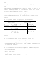
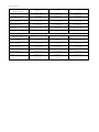
Dimensions
The following table contains the dimensions of the types of paper
and envelopes which you can use in your printer:
Single Sheets
(width x length)
A4
210 x 297 m
8.26 x 11.7 in
A5
210 x 148.5 mm
(horizontal)
8.26 x 5.85 in
US Letter
8.5 x 11 in
215.9 x 279.4 mm
US Legal
8.5 x 14 in
215.9 x 355.6 mm
US Exec
7.25 x 10.5 in
184.2 x 266.7 mm
User-defined
105 x 80 mm, min.
4.134 x 3.15 in
220 x 356 mm, max.
8.26 x 16 in
COM-10
DL
C5
C6
B5
B6
Envelopes
(width x length)
104.7 x 241.3 mm
4.125 x 9.5 in
110 x 220 mm
4.33 x 8.66 in
162 x 228mm
6.37 x 9 in
114 x 162 mm
4.4 x 6.37 in
176 x 250 mm
6.92 x 9.84 in
125 x 176 mm
4.92 x 6.92 in
Insertion
Automatic feed
The following documents can be inserted automatically from the ASF:
•
standard format single sheets (up to 40 x 80 g/m2sheets),
•
standard format coated paper (average 20 sheets),
•
standard format thicker paper/envelopes ( weight from 90 to 110<N>g/m2in packs
of not more than 10 pieces).
Semi-automatic feed
The following documents are inserted semi-automatically (loaded one at a time in
the ASF one at a time and inserted for printing using the Form Feed key):
•
user-defined documents,
•
special glossy paper,
•
transparencies.
Use only paper-backed transparencies (or film) specifically indicated for
ink-jet printers (e.g. 3M CG-3480).
The document/envelope must not be crumpled or torn, otherwise it may jam or even
not be inserted.
When using user-defined documents, remember to select the appropriate paper type
in your printer driver (see Chapter 4).
Envelopes
If you intend to print on envelopes, you must first adjust the print head
position. This operation is also indicated on the embossed template on the inside
of the top cover (the template is illustrated in Chapter 1).
•
Press Install Cartridge, to move the print head to the center of the carriage
shaft (position 4),
•
Open the top cover of the printer,
•
Turn the knob attached to the left of the print head carriage counterclockwise
to its horizontal position,
•
Insert picture page 3-3
•
Close the top cover,
•
Press Install Cartridge again, to return the print head to its rest position.
Envelopes should be inserted with their short side as the leading edge. The
printing side should be face up and the sealing flap underneath.
When using envelopes, remember to select a landscape font for printing (in
Windows® environment, you will require TrueType fonts).
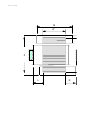
Print Area
M
W
Z
L
R
The following tables give the measurements for the print area on the standard page
and envelope sizes handled by the printer (all measurements are indicated in
millimeters and inches). The printer can print a maximum of 67 lines on an A4
page with 6 lpi line spacing (the last line may be printed with slightly defective
line spacing).
Single sheets
Format/
Measurement
M - (page width)
W - (max. print
line length
L - (min. left
hand margin)
R - (min. right
hand margin)
T - (min. top
margin)
B - (min. bottom
margin
A4
210 mm
8.26 in
203.2 mm
8 in
3.4 mm
0.134 in
3.4 mm
0.134 in
1 mm
0.04 in
12.7 mm
0.5 in
A5
(horiz.)
210 mm
8.26 in
203.2 mm
8 in
3.4 mm
0.134 in
3.4 mm
0.134 in
1 mm
0.04 in
12.7 mm
0.5 in
Letter/<R>
Legal
215.9 mm
8.5 in
203.2 mm
8 in
6.4 mm
0.25 in
6.4 mm
0.25 in
1 mm
0.04 in
12.7 mm
0.5 in
US EXEC
184 mm
7.25 in
177.8 mm
7 in
3.1 mm
0.125 in
3.1 mm
0.125 in
1 mm
0.04 in
12.7 mm
0.5 in
Your application may add its own default margins to your page layout, thus further
reducing the print area.
Pre-printed documents MUST have at least a 5 mm margin before the first print
position.
Use of documents that do not conform to the specifications indicated will result
in crooked or incorrect insertion and feed-through, with a risk of jamming.
Envelopes
Format/
Measurement
M - (width)
W - (max. print
line length)
L - (min. left
hand margin)
R - (min. right
hand margin)
T - (min. top
margin)
B - (min. bottom
margin)
Format/
Measurement
M - (max. width of
sheet)
W - (max. print
line length)
L - (min. left
hand margin)
R - (min. right
hand margin)
T - (min. top
margin)
B - (min. bottom
margin)
COM-10
DL
C5
104.7 mm
4.12 in
98 mm
3.85 in
3.4 mm
0.134 in
3.4 mm
0.134 in
1 mm
0.04 in
21.3 mm
0.84 in
110 mm
4.33 in
103 mm
4.06 in
3.4 mm
0.134 in
3.4 mm
0.134 in
1 mm
0.04 in
21.3 mm
0.84 in
162 mm
6.37 in
155 mm
6.11 in
3.4 mm
0.134 in
3.4 mm
0.134 in
1 mm
0.04 in
21.3 mm
0.84 in
C6
B5
B6
114 mm
4.4 in
107 mm
4.22 in
3.4 mm
0.134 in
3.4 mm
0.134 in
1 mm
0.04 in
21.3 mm
0.84 in
176 mm
6.92 in
162 mm
6.37 in
3.4 mm
0.134 in
3.4 mm
0.134 in
1 mm
0.04 in
21.3 mm
0.84 in
125 mm
4.92 in
118 mm
4.65 in
3.4 mm
0.134 in
3.4 mm
0.134 in
1 mm
0.04 in
21.3 mm
0.84 in
Using Software
This chapter explains how to change the printer settings by varying them in your
printer driver or using the printer set-up utility contained on the diskettes
supplied with the printer.
Your printer has a number of parameters which you can define according to your
specific requirements. Your printer driver contains most of these parameters
which can be defined when you install the driver.
Modifying the Settings in Your Printer Driver
The SuperScript™ 100C color printer driver supplied with your printer optimizes
all its features and functions. First install the driver (see Quick Start) and
then check that its default parameters are suitable for the type of document you
wish to create.
Reconfiguring the SuperScript™ 100C driver
Access to the printer parameters in the driver varies slightly, depending on your
application environment:
In Windows® 3.1/3.11:
1. Using your mouse, access Control Panel, though Program Manager and Main,
2. In Control Panel, open the Printers dialogue box, in the same way,
3. Check that your printer is selected (if not, select it),
4. Click on Setup:
In Windows® 95:
1. Using your mouse, click on Start in Desktop,
2. In the Configuration - Printers folder, highlight your printer model,
3. Click on the right button of your mouse,
4. Click on Properties, and then on the Paper tab.
At the top of the window displayed when you click Paper, are the following icons:
Automatic, Business, Photos, Art, Draft, User. Below these icons are parameters
for Paper Size, Paper Type, and Paper Source. Finally, in the lower third of the
dialog, are Number of Copies and Orientation settings.
At the bottom of the window, there are five buttons marked Clicking on the next
tab to the right, Quality, reveals the Half-toning and Print Quality settings. The
last tab, Color contains Image and Color Match parameters.
At the bottom of the window, there are six buttons marked About, Restore Defaults,
OK, Cancel, Apply, and Help, Clicking on:
About
Restore Defaults
OK
Cancel
Apply
Help
Gives publication details of the software
Restores the default values for the all parameters,
Confirms/saves all the parameter values and exits from the Setup
environment.
Ignores any changes made and causes exit from the Setup environment,
Applies all changes made prior to selection,
Gives access to more detailed information on the individual parameters
in the current window.
To change any parameter values, just click on the value or feature you require.
To move from one parameter group to another, just click on the appropriate folder
tab at the top of the window; the parameter group selected is activated and
displayed automatically.
When you have made the all changes you require, click on OK at the bottom of the
window, to save your new configuration and exit from the Setup environment.
Parameter group contents
•
Paper Size/Source:
v Paper Size: A4, Letter, Legal, A5, Executive, COM10,
v C5, DL, User-Defined (default setting: A4 or Letter,depending on country).
v Paper Source: Auto Sheet Feeder, Manual.
v Portrait or Landscape.
v Copies: Collate or Reverse Page Order.
•
Paper Type/Print Quality
v Paper Type: Plain Paper, Transparency, Glossy Paper, Coated Paper.
v Print Quality: Standard, Draft (High Speed), Economy, High Quality,
Presentation.
This group of values is disabled, if Automatic (default value) is selected in
the parameter group Document Type.
•
Document Type
Automatic, Monochrome Report, Color Report, Greyscale Picture, Color Picture,
Draft Printing.
•
Print head/Resolution
v Print head: Monochrome, Color (CMY).
This group of values is disabled, if Automatic (default value) is selected in
the parameter group Document Type.
v Resolution: 600 x 300, 300 x 300, 150 x 150, 75 x 75 dots per inch.
Dithering
No Dithering, Line Art Pattern, Fine Pattern, Coarse Pattern, Standard
Spray, High Quality Spray, Presentation Quality Spray.
This group of values is disabled, if Automatic (default value) is selected in
the parameter group Document Type.
Image Settings
v Image: Brightness and Contrast (two sliding bars).
v Enable Ink Density Correction (enabled; click on box to disable).
v Color Balance: Saturation, Red Intensity,
v Green Intensity, Blue Intensity (four sliding bars).
v Color Match (enabled; click on box to disable).
Help
Each active window in the driver setup has an extensive module of detailed
information which can be accessed by clicking on the Help button at the foot of
the window.
Document type
If the parameter value Automatic is selected in this menu, the Print Quality,
Printhead and Dithering menus are disabled. The values for these parameters will
be set automatically.
Fonts
Scalable and/or TrueType fonts are available when you operate in a Microsoft
Windows environment, level 3.1 or later. These fonts are stored mathematically as
character and symbol outlines and are expanded only when the specific font is
selected.
You cannot use the printer's resident fonts in Windows environment.
the fonts available in Windows.
You must use
Print quality
High Quality (LQ)
Presentation
Draft
Economy
gives
gives
gives
saves
a combination of speed and good
best quality at a lower speed
fast printing
ink
Paper type
If you select Transparency, output will be LQ, regardless of the print quality
parameter setting selected.
DOS Environment
If you use a DOS Software program, you will require a specific driver for each
printer model and application to access the main features of your printer. Ask
your computer dealer for advice.
To install any of the drivers, always refer to the specific software application
documentation. Should any of the parameters you require not be accessible through
the driver, you can access them using the printer SETUP utility.
Your printer has two resident emulation's: PCL III + (default value) and IBM
Proprinter X24 Model 4207/1 that may be used with DOS applications:
PCL III + mode:
Choose the PCL III + driver when setting your application software. If PCL III +
is not available, choose HP DeskJet 500C or HP DeskJet 500. The PCL III + mode
supports both color and black printing.
IBM Proprinter X24 mode:
Choose the IBM Proprinter X24 Model 4207/1 driver when setting your application
software. Note that this mode only supports black printing with the black print
head. Attempting to print with the color print head installed will result in an
error condition. The "demo" page is not available if this emulation is selected.
Running the Printer Set-Up Utility
This program is aimed at DOS-based applications. It should be used
if the feature you require cannot be selected through the driver you
have installed or if no driver is available.
We suggest that you make a copy this program on another diskette, and keep the
original as a master.
Note for Windows® 95 users
If you have Windows<190> 95 installed on your PC, BEFORE running the SETUP
utility, you must disable the DOS spooler, as follows:
1. In the Printers folder, select your printer then Properties tab.
2. In the Details sheet, click on the Port Settings button.
3. A window entitled Configure LPT ports opens, with the option Spool MS-DOS print
jobs selected.
4. Click on the box, to deactivate the option. This will enable the DOS
application to handle the port directly.
5. Close Windows® 95.
To re-enable the "Spool MS-DOS print jobs" feature, just repeat the above
procedure.
To run the SETUP utility, proceed as follows:
Insert the diskette containing the SETUP utility in drive a (usually) of your
computer.
At the DOS prompt, type A:\ (or B:\)STUP100C.EXE, and press ENTER.
The program will read the printer's identification code and its internal settings.
It will then display this information on your PC screen.
If you click on Change Parameters, the parameter group selection screen for the
emulation currently selected is displayed.
You can now select, one at a time, the parameter groups containing the feature(s)
you wish to change.
See also Appendix B for a complete list and description of the parameters
available.
If you click on Factory Default, you restore the default settings within the
emulation currently selected.
If you click on Quit, you abandon the SETUP utility and return to DOS. If any
settings were changed, you will be prompted to "Save setup into printer?".
The parameter settings defined in the driver always have priority over the
settings made using the SETUP utility.
Troubleshooting
This chapter contains a troubleshooting guide which indicates some of the problems
which may occur during the day-to-day use of your printer, together with
suggestions for their solution. Your printer is designed to require only minimum
maintenance. However, everyday use will give rise to a number of simple printercare operations.
If you detect serious mechanical damage to or a failure in the printer, do not
attempt to repair it yourself! CALL THE TECHNICAL SUPPORT CENTER.
General Care
1. Environment
•
Keep your printer in a stabilized, ventilated environment (temperature
range: 5 to 35°C; relative humidity: 15% - 85%).
•
Do not subject your printer to abrupt changes in temperature and/or humidity.
•
Do not let dust accumulate on the printer casing. Use a slightly damp cloth to
remove dust.
•
Do NOT use abrasive or corrosive cleaning fluids to clean the printer casing.
2. Transportation
•
Always make sure that the print head is in its rest position. To ensure this,
always unplug your printer BEFORE switching of the host to which it is
connected.
•
Take care not to drop your printer.
•
Repack your printer in its original carton, whenever possible.
Error Conditions indicated by Print Head Position
On the inside of the top cover, there is an embossed template which, as well as
illustrating the print head insertion/ replacement procedure, indicates the most
common reasons for an interruption in the printer operation (the template and its
contents are illustrated in Chapter 1).
When an error occurs, printing stops, On Line and Power LED's flash simultaneously
and the print head position will correspond to one of the action items indicated
on the embossed template:
1.
Check paper
2.
Change black/color lever position
3. Change ink cartridge
4. Change print head.
Correct the error and then press Install Cartridge to return the print head to its
rest position.
Problems and Solutions
If you have problems while working with the printer, check through the following
list, to see if you can find the cause of the problem.
If a printer malfunction other than those indicated below occurs, or if, after
executing the suggested corrective action, the problem persists, call your
retailer or the Technical Support Center.
During normal printer operation, an error condition will be signaled by the
simultaneous flashing of the On Line and Power LED's. When you open the top cover
of the printer, the print head carriage will be positioned above the corresponding
action item on the embossed template.
Installation
1. Missing or damaged parts.
•
Contact your retailer immediately.
2. Printer is not powered.
No power supply (no LED's are lit).
•
Check that the printer is connected properly to the power supply socket.
If no LED's are lit, but the printer is powered, it is in standby condition. Press
any key to return the printer to its operating status.
3. No initial reset.
When the printer is plugged into the electrical power supply, the print head
carriage does not move.
•
Check that the carriage path is free of impediment.
•
Try disconnecting the printer from the power supply and then plugging it in
again.
•
If the Power and On Line LED's are flashing rapidly, there is a failure on the
mother board; call the technical assistance service.
4. Demo page did not run.
•
If the carriage does not move, check that its path is not obstructed.
•
Disconnect the printer from the electrical power supply and then plug it in
again. Repeat the key sequence.
•
If the Power and On Line LED's flash simultaneously, open the top cover to
check the position of the print head carriage, which will have moved to
indicate the operator action required:
v there is no paper in the printer; load paper in the ASF and press Form Feed
on the operator panel.
v the print head (ink cartridge) needs replacing; follow the instructions
given in the appropriate sections in Chapter 1, to replace the print
head/ink cartridge.
v check that the print head is inserted correctly; if it is not, remove and
reinsert it. Remember to press Install Cartridge once you have reinserted
the print head.
5. Problems with connection to host.
•
Check that your interface cable is of the correct type.
•
Make sure you have fixed the interface connectors properly both to the printer
and to the host.
•
Check that you have configured your application correctly (see the driver
installation procedure in Chapter 4 and your application manual).
Paper
Precautions
•
The paper must not be crumpled or torn, otherwise it may jam or even not be
inserted. Always use paper in perfect condition and within the specifications
defined (see Chapter 3).
•
Make sure the paper feeds smoothly, and that it is not held too tightly nor has
too much play.
•
If you remove the paper from or add paper to the ASF, you MUST repeat the
entire paper loading operation.
•
Always make sure there is no paper inserted for printing before disconnecting
the printer from the mains power supply or before doing the head clearing
operation (see the section entitled "Clearing the print head nozzles" in
Chapter 2).
•
Printing on both sides of the paper may cause smudging.
No paper
•
If, on a print command, there is no paper to load in the printer, the Power and
On Line LED flash slowly.
•
To clear this condition, load paper in the ASF and press Form Feed.
2.
Paper does not load.
Check that the size and weight of the paper used are within the limits allowed.
Press Form Feed, then repeat the paper loading operation.
•
If you removed the paper from the ASF, you must press Form Feed, repeat the
entire paper loading operation and then press Form Feed again.
•
Make sure the paper is not feeding in crookedly.
•
Paper jamming - point 4 in this section.
•
Make sure the correct paper feed parameter is selected in your printer driver,
load paper in the ASF and press the Form Feed key on the operator panel.
3.
Single sheets/envelopes not loaded (or loaded incorrectly).
•
The document/envelope has been positioned incorrectly for insertion.
•
Make sure the correct paper format parameter is selected in your printer
driver.
•
The print head adjustment lever is positioned incorrectly for the type of
document you are using (see the section entitled "Envelopes" in Chapter 3).
•
Preprinted documents must have a clean 5 mm margin before the first print
position.
•
•
Document is being fed with a reduced linefeed, causing overprinting of
successive print lines. ASF feed mechanism is not synchronized correctly.
Remove all the paper from the ASF, press Form Feed and then reload the paper in
the ASF.
.
Paper jams or tears.
•
The most common causes of paper jamming in the ASF is the addition of paper
when the tray is not empty and/or the incorrect loading of paper.
•
When adding paper to the ASF, ALWAYS remove any paper already present and
reload it all as a single pack.
•
After clearing a paper jam, ALWAYS remove any paper still in the ASF, press
Form Feed and then reload the paper.
•
If the paper has already exited from the print area:
v set the printer OFF LINE (On Line LED off)
v open the top cover and remove the jammed paper.
To resume printing, close the top cover and the paper tray, and then press
On Line.
•
If the paper jams in the ASF:
v disconnect the printer from the mains power supply
v remove the damaged page(s) from the ASF. Remove the rest of the paper, fan
and square it and then reload it in the ASF.
•
5.
•
Do not attempt to print on small adhesive labels attached to larger size glossy
paper (e.g. A4 format). This type of label tends to detach during printing and
recovery from inside the printer is difficult.
Incorrect stacking.
Too many sheets of paper in the output tray.
40 standard weight printed pages.
The output tray can contain up to
Heavily printed pages tend to curl and may not stack correctly. They may also
stain the rear of the page stacked over them, as they require longer to dry.
Always remove such pages from the output tray as soon as they are expelled from
the printer.
Print head
When changing the print head, take care not to touch the print head carriage shaft
nor the area under the print head carriage.
1.
•
2.
Printer does not print
Check that you have removed the protective film from the print head.
Print head carriage does not return to the rest position after a replacement
operation.
•
Check that the position of the print head selection lever corresponds to the
type of print head you have inserted.
•
Check that nothing is blocking the carriage path.
3.
•
Characters are faint.
Execute the print head clearing operation to clean the nozzles.
Make sure there is no paper in the printer.
Check that the print head carriage position lever is compatible with the type of
document being printed.
4. Missing dots
If dots or lines are not printed completely, remove the ink jet print head and
reinsert it, or:
•
Execute the print head cleaning operation.
•
Execute the nozzle clearing operation.
•
Clean the electrical contacts on the print head and those in its chamber.
For all these operations, see the appropriate sections in Chapter 2.
After cleaning the print head or executing the nozzle clearing operation, print a
"demo" page to check the print quality. If the print quality is still not
acceptable, run a print test.
To run the print test, proceed as follows:
•
Make sure that the print head is inserted and that there is paper in the ASF.
•
Press and hold the On Line key, and then press the Install Cartridge and
Form Feed keys on the operator panel until the light indicators go off.
•
Press the On Line key three times.
•
A sheet of paper will be fed into the printer and the print test will be
executed automatically.
To suspend the print test temporarily, press On Line (pressing this key a second
time will cause printing to resume).
Once the test is completed and the sheet of paper is expelled, the printer will go
automatically into ON-LINE condition.
Check the print quality of the test, making sure that all the characters are
clearly defined and complete.
Monochrome print test contents
The monochrome print test contains information on the printer firmware (release,
emulation and character generators) and the correct operation of the print head
nozzles:
The first line of the print test contains technical information on the printer
status.
The second line of print test indicates the print head type.
The third line of the print test (Print Head Test), consists of a diagonal line,
indicating the performance of the head nozzles and the result line (Pass, or Fail
with the number(s) of the faulty nozzle(s)). It allows you to check whether any
dots are missing.
If dots are missing, see the section entitled Clearing the print head
nozzles in Chapter 1 for the possible solutions to this problem. Then
repeat the print test.
•
The rest of the print test contains the currently selected values for the
programmable parameters and a print-out of the current selected character set.
In most cases, the parameter settings will be determined by your printer driver.
If you wish to modify your printer set-up, see Chapter 4 - "Using Software".
Color print test contents
The color print test consists of three bands of color (one for each of the basic
colors in the print head) printed three times, preceded and followed by the
diagonal line and numbering of the nozzle test which allows you to check the
correct operation of each group of nozzles.
The short colored band under the beginning of the diagonal line of the nozzle test
indicates the correct functioning (blue) or not (red) of the print head contacts.
If any nozzle numbers are missing, the nozzles should be cleared (see
Print Head Care in Chapter 2).
If none of these operations result in improved print quality, you must replace the
print head.
Printing
During a printing operation, do not stop the print head manually nor touch the
area within the print head carriage path.
1.
Printer does not print/receive data.
•
Check that the printer is connected to the electrical power supply and On Line
(the Power and On Line LED's on the operator panel should be lit).
•
Check the physical (cables) and logical (application and driver) connections
between the printer and host.
•
Check that host system is switched on.
•
If the print head carriage does not move and the Power and On Line LED's flash
rapidly, disconnect and reconnect the printer to the electrical power supply.
If the Power and On Line LED's continue to flash rapidly, call the Technical
Assistance Service.
•
Check that you have removed the protective film from the print head.
•
If the Power and On Line LED's flash slowly, check that paper is present and
that it loads correctly, then press Install Cartridge.
•
2.
Check whether the printer is in the special functions mode (printer powered but
both LED's off).
Printing stops.
If the On Line and Power LED's flash simultaneously, open the top cover to see
which error condition the print head carriage position indicates.
Check that paper is present and that it loads correctly. If there is no paper in
the printer, load up to 40 sheets of paper in the ASF and press the Form Feed key
on the operator panel.
See Chapter 3 for the correct paper loading procedure.
•
Change the print head.
See Chapter 2 for replacing the print head.
3.
Poor print quality
•
Execute the print head clearing operation to clean the nozzles.
•
Try printing on the other side of the paper.
•
Make sure you are using good quality paper.
•
Check that the print head carriage position lever is compatible with the type
of document being printed.
4. Your printer has a color print head, but printing is monochrome.
•
5.
Check that your printer driver handles color printing.
Strange characters are printed
•
Check that you are using the correct emulation.
•
Check that the driver you have selected is compatible with the emulation you
intend to use.
•
Check that the character set you require is selected (the currently selected
parameters, including the character set, are given in the monochrome print test
- see the previous section of this chapter).
•
You have pressed the key combination for the "demo" page, but the print test is
printed. Check the emulation currently selected; the "demo" page is available
only in PCL III + emulation.
•
If you cannot solve this problem, your hot line service may request to run a
hex-dump of a test piece to check that the data transmission is operative. To
run the hex-dump, proceed as follows:
v Press all three keys simultaneously, then press in sequence
Feed, Install Cartridge.
On Line, Form
v Send a short text file from your computer. The content of this file is
printed as a string of hexadecimal codes corresponding to the individual
characters transmitted.
v To exit from hex-dump mode, hold On Line and press Form Feed(RESET).
6. Print test executed correctly, but unable to print in Windows® environment
The printer driver may not be installed correctly.
•
Check that the name of the printer appears in the List of printers in the
Printers dialogue box:
v If the printer name is not listed, install it following the driver
installation procedure described in the Quick Start.
v If the printer name is listed, remove it from the list by clicking on the
Remove button in the Printers dialogue box and then repeat the driver
installation procedure.
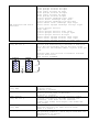
Supplies
The following items can be ordered from your retailer.
individually and have specific instructions booklets.
•
Single color print head.
•
Single monochrome print head.
They are packed
The SuperScript 100C is compatible with most inkjet papers (coated and uncoated).
For optimum print quality, we recommend the following paper types:
•
HP Premium coated inkjet paper
•
HP Premium glossy paper.
Printer Settings
This appendix contains a brief description of the printer settings available with
the resident emulation's, using the printer setup utility.
Factory Settings
When you receive the printer, its basic operating parameters are already
set with pre-defined factory settings (default settings for PCL III+ emulation).
These are the settings which appear in the print test the very first time you run
it (see specific section in Chapter 5).
Your printer emulation is set to be compatible with the diskette included with
your printer. You should not have to vary anything. If you wish to change the
emulation, remember to check that it is compatible with your application driver,
otherwise your printer will not operate correctly.
Parameter Description
The following tables give a brief description of all the features which can be
selected using the printer set-up utility. Where indicated, the features are
valid only for a specific emulation.
Feature
Emulation
Paper Format
Paper Device
Perforation skip mode (Skip
Over)
Description
Set of command codes,, character sets and fonts
used: PCL III +; IBM Proprinter X24 4207/1.
Indicates the type and dimensions of the document to
be printed:
Letter; Legal; A4; horizontal A5; COM10; DL; C5;
Executive; Free;C6; B5; B6.
Means by which paper is fed to the printer:
ASF.
Affects only text, introducing a half inch (12.7 mm)
no-printing area at the top of each page. In most
cases, Perforation skip mode ON will meet your
requirements.
When Perforation skip mode is ON, a line that
overruns the lower limit of the text area will be
printed below the top margin of the next page.
When Perforation skip mode is OFF, the line will be
printed on the first physical print line of the new
page.
ENABLED (ON)
DISABLED (OFF)
Page 1
BOF = 1/2 in
BOF = 1/2 in
TOF = 1/2 in
TOF = 0
Page 2
Print Quality
Graphic resolution
(only PCL III + )
Type of printing quality:
LQ (Letter Quality) or Draft.
Graphic printing resolution (dots per
inch - dpi):75; 100; 150; 300.
Line Feed Length
(only IBM)
Line Terminator
Line Feed Value: nominal distance
between the base of one print line and
the next. This value may be expressed as
a number of lines per inch (lpi) or as
an absolute value (inches or
millimeters):
6 lpi; 8 lpi; 7/72";5mm
Normal: CR=CR; LF=LF; FF=FF
AutoLF: CR=CR+LF; LF=LF; FF=FF
AutoCR: CR=CR; LF=LF+CR; FF=FF+CR
AutoCRLF: CR=CR+LF; LF=LF+CR; FF=CR+FF
Character sets
Character Set: set of national or specialized
characters/ symbols to be used for printing:
PCL III + emulation:
CP 437 International
Roman 8
PC-8 Denmark/Norway
CP 850 (multilingual)
ECMA 94 Latin 1
ISO 4 United Kingdom
ISO 21 Germany
ISO 69 France
ISO 15 Italy
ISO 60 Norway 1
ISO 61 Norway 2
ISO 11 Sweden Names
ISO 10 Sweden
ISO 17 Spain
ISO 6 USASCII
ISO 2 IRV
ISO 16 Portugal
ISO 14 JIS ASCII
Legal
CP 860 Portugal
Danish OPE I
UNIX International
Danish OPE II
Spain II
CP 863 French Canadian
PC Abicomp International
PC Abicomp Portugal
IBM Proprinter X24 4207/1
emulation:
CP 437 International
Danish OPE I
Danish OPE II
Spain II
CP 850 (multilingual)
CP 860 Portugal
Type Style (Font)
Shape, size, spacing,, etc. of the character/
symbol set printed:
PCL III + emulation:
Courier Upright Portrait 10cpi 12pts
Courier Italic Portrait 10cpi 12pts
Courier Upright Portrait 16.67cpi 12pts
Letter Gothic Upright Portrait 10cpi 12pts
Letter Gothic Upright Portrait 12cpi 12pts
Letter Gothic Italic Portrait 12cpi 12pts
Letter Gothic Upright Portrait 16.67cpi 9.5pts
Team Nordic Upright Portrait PS 12pts
Team Nordic Italic Portrait PS 12pts
BF Team Upright Portrait PS 14pts
BF Team Italic Portrait PS 14pts
BF Team Upright Portrait PS 12pts
BF Team Italic Portrait PS 12pts
BF Team Upright Portrait PS 10pts
BF Team Italic Portrait PS 10pts
BF Team Upright Portrait PS 8pts
IBM Proprinter X24 4207/1
emulation:
BF Team Italic Portrait PS 8pts
Linea Upright Portrait PS 14pts
Linea Upright Portrait PS 12pts
Linea Italic Portrait PS 12pts
Linea Upright Portrait PS 10pts
Linea Italic Portrait PS 10pts
Linea Upright Portrait PS 8pts
Courier Upright Landscape 10cpi 12pts
Courier Italic Landscape 10cpi 12pts
Courier Upright Landscape 16.67cpi 12pts
Letter Gothic Italic Landscape 12cpi 12pts
Letter Gothic Upright Landscape 16.67cpi 9.5pts
Courier Upright Portrait
10cpi 12pts
Courier Upright Portrait 12cpi 12pts
Courier Upright Portrait 17.14cpi 12pts
Courier Upright Portrait PS 12pts
Letter Gothic Upright Portrait 10cpi 12pts
Letter Gothic Upright Portrait 12cpi 12pts
Letter Gothic Upright Portrait 17.14cpi 12pts
Text Scale Mode
(only PCL III +)
Affects only text,, reducing automatically the
current Line Feed setting to maintain a half-inch
(12.7 mm) non-printable area at the foot of the
page even for the maximum number of print lines per
page.
Possible ONLY with portrait orientation selected
and the Perforation
Skip feature DISABLED
DISABLED
ENABLED
63 lines
66 lines
of text
of text
11 in
(Letter size)
BOF = 12.7 mm
Slashed Zero
(only IBM)
Ink Save Mode
Width Type<R>
(only PCL III +)
PC Table
(only IBM)
AGM (only IBM)
Indicates whether or not the zero is printed with a
diagonal slash:
disabled or enabled.
Procedure for reducing the volume of inking on
heavily printed pages in BIM mode:
disabled or enabled.
Defines the dimensions of the character/symbol
printed, according to the FONT selected (see
parameter). Some fonts are not affected:
normal; half width; half height; half width and
half height.
PC Table: determines which area of the currently
selected character set table will be used:
Table 2 or Table 1.
Alternative Graphics Mode: additional command codes
for printing graphics,, which may be used when the
IBM emulation is active:
disabled or enabled.
Baud Rate
Parity
Handshake
Data transmission speed:
2400, 9600, 19200, 38400 Baud.
This parameter is effective only if the optional
serial interface
is connected.
Type of data control method:
None, Even, Odd.
This parameter is effective only if the optional
serial interface
is connected.
, Type of data exchange procedure:
SOFT (Xon/Xoff + DTR) or HARD (DTR).
This parameter is effective only if the optional
serial interface is connected.
Command Codes
This appendix contains a summary of the command codes sets handled by the resident
emulation's
Introduction
When the printer is set for a particular emulation, it will interpret ONLY the set
of commands belonging to that emulation.
A printer command consists typically of one or more characters imbedded in the
flow of data transmitted to the printer. To make the printer understand which
characters are to be interpreted as commands and which as printable characters,
there is a simple built-in convention: all "characters" that have, according to
the character table, a decimal value less than 32 are interpreted as control
codes. Some of them result in an action, when they are received, others do not.
The ones causing printer action can be found in the command code description.
There is also a special command ESCAPE (decimal code 27, named ESC) which
is used by most printer emulation's to open a command sequence. It is followed by
one or more additional characters, which are identifiers and parameters, belonging
to the printable characters or to those from the range of control codes.
If your printer receives commands which are not compatible with the emulation in
use, it will ignore them, print them as normal characters or even block. Whatever
happens, no serious harm will be done to your printer. To clear the situation,
just reset the printer (hold On Line and press Form Feed for approximately 3
seconds).
PCL III + Multiple ESCape Sequences
If the consecutive ESCape sequences you send to the printer have the same two
characters after the character ESC, you can save time by sending a single multiple
ESC sequence to the printer. This multiple sequence will consist of the ESC
character, the two common character which follow ESC and the remaining characters
of each individual command.
E.g.: if you have to send the sequences: ESC ( s 3 B, ESC ( s 3 T and ESC(s1Q, you
can do so using the multiple sequence ESC ( s 3 b 3 t 1 Q. Note that the last
character of the first two sequences "B" and "T" have become lower case ("b" and
"t" respectively), while the last character of the last sequence
("Q") has remained upper-case (indicating, thus, the end of the multiple
sequence).
PCL III + Attribute Selection Priority
Font
The font selection MUST ALWAYS be indicated in the following order:
1. Print orientation (PORTRAIT or LANDSCAPE)
2. Character set (CP 437, etc.)
3. Character position on the print line (normal, superscript, subscript)
4. Spacing (fixed or proportional)
5. Print pitch
6. Character height (dots)
7. Style (upright or italic)
8. Stroke weight (medium or bold)
9. Typeface (Courier, etc.)
10.Print quality (DRAFT, NLQ, LQ).
Page layout
The page layout selection MUST ALWAYS be indicated in the following order:
1. Line feed value
2. Page length
3. Top of form value
4. Print area.
Bear these priorities in mind when you send the ESCape sequences for the various
parameters, to avoid any surprises.
Command Code Summary
PCL III + Emulation
BASIC OPERATIONS
BS
8
HT
9
LF
10
FF
12
CR
13
SO
14
SI
15
SP
32
DEL
127
08
09
0A
0C
0D
0E
0F
20
7F
Backspace
Horizontal Tabulation
Line Feed
Form Feed
Carriage Return
Activates Secondary Font
Activates Primary Font
Space
Delete (ignored)
FONTS AND CHARACTER SETS
ESC ( n @
27 40 n 64
ESC ( 0 @
27 40 48 64
1B 28 n 40
1B 28 30 40
ESC ( 1 @
ESC ( 2 @
27 40 49 64
27 40 50 64
1B 28 31 40
1B 28 32 40
ESC ( 3 @
27 40 51 64
1B 28 33 40
Primary Font Definition
Designates default primary character
set as primary font
Same as for ESC ( 0 @
Designates current primary character
set as primary font
Selects the default primary font
ESC ) n @
ESC ) 0 @
27 41 n 64
27 41 48 64
1B 29 n 40
1B 29 30 40
ESC ) 1 @
27 41 49 64
1B 29 31 40
ESC ) 2 @
27 41 50 64
1B 29 32 40
ESC ) 3 @
27 41 51 64
1B 29 33 40
Secondary Font Definition
Designates the default character set as
the secondary font
Designates the default primary font as
the secondary font
Designates the current primary font as
the secondary font
Selects the default secondary font
ESC & l 0 O
ESC & l 1 O
27 38 108 48 79
27 38 108 49 79
1B 26 6C 30 4F
1B 26 6C 31 4F
PORTRAIT Print Orientation
LANDSCAPE Print Orientation
(continued)
FONTS
ESC (
ESC (
ESC (
ESC (
ESC (
ESC (
ESC (
ESC (
ESC (
ESC (
ESC (
ESC (
ESC (
ESC (
ESC (
ESC (
ESC (
ESC (
ESC (
ESC (
ESC (
ESC (
ESC (
ESC (
AND CHARACTER SETS (continued)
n m
27 40 n m
1B 28
10 U
27 40 49 48 85
1B 28
8 U
27 40 56 85
1B 28
11 U
27 40 49 49 85
1B 28
12 U
27 40 49 50 85
1B 28
0 N
27 40 48 78
1B 28
1 E
27 40 49 69
1B 28
1 G
27 40 49 71
1B 28
1 F
27 40 49 70
1B 28
0 I
27 40 48 73
1B 28
0 D
27 40 48 68
1B 28
1 D
27 40 49 68
1B 28
0 S
27 40 48 83
1B 28
3 S
27 40 51 83
1B 28
2 S
27 40 50 83
1B 28
0 U
27 40 48 85
1B 28
2 U
27 40 50 85
1B 28
4 S
27 40 52 83
1B 28
0 K
27 40 48 75
1B 28
1 U
27 40 49 85
1B 28
33 I
27 40 51 51 7
1B 28
35 P
27 40 51 53 80
1B 28
13 U
27 40 49 51 85
1B 28
34 P
27 40 51 52 80
1B 28
n m
31 30
38 55
31 31
31 32
30 4E
31 45
31 47
31 46
30 49
30 44
31 44
30 53
33 53
32 53
30 55
32 55
34 53
30 4B
31 55
33 33
33 35
31 33
33 34
55
55
55
49
50
55
50
Primary Character Set Definition
CP 437 International
Roman8
PC 8 Denmark/Norwary
CP 850 (Multilingual)
ECMA-94 Latin 1
ISO 4 - United Kingdom
ISO 21- Germany
ISO 69 - France
ISO 15 - Italy
ISO 60 - Norway 1
ISO 61 - Norway 2
ISO 11 - Sweden Names
ISO 10 - Sweden
ISO 6 - ASCII
ISO 2 - IRV
ISO 16 - Portugal
ISO 14 - JIS ASCII
Legal
CP 860 Portugal
Danish OPE I
UNIX International
Danish OPE II
Spain II
ESC
ESC
ESC
ESC
(
(
(
(
33
34
59
60
P
I
P
P
ESC ) n m ...
PRINT
ESC (
ESC (
ESC (
27
27
27
27
40
40
40
40
51
51
53
54
51
52
57
48
80
73
80
80
1B
1B
1B
1B
27 41 n m ...
28
28
28
28
33
33
35
36
33
34
39
30
50
49
50
50
CP 863 French Canadian
PC Abicomp International
PC Abicomp Portugal
1B 29 n m ...
ATTRIBUTES
s + 1 U
27 40 115 43 49 85
s - 1 U
27 40 115 45 49 85
s 0 U
27 40 115 48 85
Secondary Character Set Definition
(values of n and m as for ESC ( )
1B 28 73 2B 31 55
1B 28 73 2D 31 55
1B 28 73 30 55
Superscripts
Subscripts
Clears Superscripts/
Subscripts
Selects Fixed Horizontal
Spacing
Selects Proportional
Horizontal Spacing
ESC ( s 0 P
27 40 115 48 80
1B 28 73 30 50
ESC ( s 1 P
27 40 115 49 80
1B 28 73 31 50
ESC ( s n H
27 40 115 n 72
1B 28 73 n 48
ESC ( s 5 H
ESC ( s 6 H
ESC ( s 8.33 H
1B
1B
1B
33
1B
1B
1B
36
1B
1B
1B
33
1B
1B
35
1B
1B
56
1B
1B
28
28
28
48
28
28
28
37
28
28
28
33
28
28
56
28
28
ESC ( s 12 V
ESC ( s 24 V
27
27
27
51
27
27
27
54
27
27
27
51
27
27
53
27
27
86
27
27
28 73 31 30 56
28 73 32 34 56
Selects 12 point character
Selects 24 point character
(continued)
PRINT
ESC (
ESC (
ESC (
ESC (
(continued)
27 40 115 48
27 40 115 49
27 40 115 48
27 40 115 51
1B
1B
1B
1B
28
28
28
28
53
53
42
42
Upright Print Style
Italic Print Style
Medium Stroke Intensity
Bold Stroke Intensity
Defines Character
Typeface
Selects Courier typeface
Selects Team Nordic tp.
Selects Letter Gothic tp.
Selects BF Team typeface
ESC ( s 10 H
ESC ( s 12 H
ESC ( s 16.67 H
ESC ( s 20 H
ESC ( s 24 H
ESC ( s 33.33 H
ESC ( s n V
ESC ( s 4.25 V
ESC ( s 6 V
ESC ( s 9.5 V
ATTRIBUTES
s 0 S
s 1 S
s 0 B
s 3 B
40
40
40
72
40
40
40
55
40
40
40
51
40
40
86
40
40
115 53 72
115 54 72
115 56 46 51
115
115
115
72
115
115
115
72
115
115
49 48 72
49 50 72
49 54 46
50 48 72
50 52 72
51 51 46
n 86
52 46 50
115 54 86
115 57 46 53
40 115 49 50 86
40 115 50 52 86
83
83
66
66
73 35 48
73 36 48
73 38 2E 33
73
73
73
48
73
73
73
48
73
73
32 30 48
32 34 48
33 33 2E
Selects 20 cpi pitch
Selects 24 cpi pitch
Selects 33.33 cpi pitch
n 56
34 2E 32
Defines Character Height
Selects 4.25 point char.
30
31
30
33
27 40 115 n 84
1B 28 73 n
54
ESC
ESC
ESC
ESC
27
27
27
27
49
27
56
1B
1B
1B
1B
31
1B
38
54
54
54
31 30
s
s
s
s
3 T
5 T
6 T
4101 T
ESC ( s 4148 T
40
40
40
40
84
40
84
115
115
115
115
51
53
54
52
84
84
84
49 48
115 52 49 52
28
28
28
28
54
28
54
73
73
73
73
5 cpi pitch
6 cpi pitch
8.33 cpi pitch
Selects 10 cpi pitch
Selects 12 cpi pitch
Selects 16.67 cpi pitch
ESC ( s n T
(
(
(
(
Fixed Horizontal
31 30 48
31 32 48
31 36 2E
73 36 56
73 39 2E 35
73
73
73
73
Defines
Pitch
Selects
Selects
Selects
33
35
36
34
73 34 31 34
Selects 6 point character
Selects 9.5 point character
Selects Linea typeface
ESC ( s 1 Q
ESC ( s 9 Q
ESC ( s 2 Q
27 40 115 49 81
27 40 115 57 81
27 40 115 50 81
1B 28 73 31 51
1B 28 73 39 51
1B 28 73 32 51
DRAFT Printing
DRAFT Printing
LETTER QUALITY Printing
ESC & d n D
ESC & d 0 D
27 38 100 n68
27 38 100 48 68
1B 26 64 n 44
1B 26 64 30 44
ESC & d 1 D
27 38 100 49 68
1B 26 64 31 44
ESC & d 2 D
27 38 100 50 68
1B 26 64 32 44
Defines Underscore
Selects fixed single
under- score (default)
Selects fixed single
under- score
Selects fixed double
underscore
ESC & d 3 D
27 38 100 51 68
1B 26 64 33 44
ESC & d 4 D
27 38 100 52 68
1B 26 64 34 44
ESC & d @
ESC & k n E
27 38 100 64
27 38 107 n 69
1B 26 64 40
1B 26 6B n 45
PAGE FORMAT
ESC & l n A
ESC & l 0 A
ESC & l 1 A
ESC & l 2 A
ESC & l 3 A
ESC & l 26 A
ESC & l 29 A
ESC & l 81 A
27
27
27
27
27
27
27
27
1B
1B
1B
1B
1B
1B
1B
1B
ESC & l 90 A
27 38 108 57 48 65
1B 26 6C 39 30 41
ESC & l 91 A
27 38 108 57 49 65
1B 26 6C 39 31 41
ESC & l 92 A
27 38 108 57 50 65
1B 26 6C 39 32 41
ESC & l 94 A
27 38 108 57 52 65
1B 26 6C 39 34 41
ESC & l 95 A
27 38 108 57 53 65
1B 26 6C 39 35 41
ESC & l 93 A
27 38 108 57 51 65
1B 26 6C 39 33 41
ESC & l n L
27 38 108 n 76
1B 26 6C n 4C
Skip over Bottom of Form
(1 = enables; 0 = disables)
ESC & l n D
27 38 108 n 68
1B 26 6C n 44
ESC & l n C
27 38 108 n 67
1B 26 6C n 43
Line Feed (in LPI) n may
vary,, compatibly with font
used)
Line Feed (in n/48 in)
(1 ⊆ n ⊇ 126)
ESC & l n P
27 38 108 n 80
1B 26 6C n 50
Page Length (n may vary,
compatibly with physical
page size used)
ESC =
27 61
1B 3D
Half Line Feed Forward
ESC & a n L
27 38 97 n 76
1B 26 61 n 4C
ESC & a n M
27 38 97 n 77
1B 26 61 n 4D
ESC 9
27 57
1B 39
Left Margin (0 ⊆ n ⊇ 78;
with 10 cpi pitch)
Right Margin (1 ⊆ n ⊇ 79;
with 10 cpi pitch)
Clears Left and Right
Margins
ESC & l n E
27 38 108 n 69
1B 26 6C n 45
27 38 108 n 70
1B 26 6C n 46
38
38
38
38
38
38
38
38
108
108
108
108
108
108
108
108
n 65
48 65
49 65
50 65
51 65
50 54 65
50 57 65
56 49 65
26
26
26
26
26
26
26
26
6C
6C
6C
6C
6C
6C
6C
6C
n 41
30 41
31 41
32 41
33 41
32 36 41
32 39 41
38 31 41
ESC & l n F
VERTICAL POSITIONING OF CURSOR
ESC & a N R
27 38 97 n 82
1B 26 61 n 52
ESC & a + n R
ESC & a - n R
27 38 97 43 n 82
27 38 97 45 n 82
1B 26 61 2B n 52
1B 26 61 2D n 52
ESC * p n Y
27 42 112 n 89
1B 2A 70 n 59
Selects variable single
underscore
Selects variable double
underscore
Clears Underscore
Underscore for One Line
(0=one line;1=continuous)
Defines
Selects
Selects
Selects
Selects
Selects
Selects
Selects
Paper Format
default paper format
US Executive format
US Letter format
US Legal format
A4 format
horizontal A5 format
COM 10 envelope size
Selects International DL
envelope size
Selects International C5
envelope size
Selects International C6
envelope size
Selects International B5
envelope size
Selects International B6
envelope size
Selects US Executive format
Top of Form (TOF)
(n= no. of print lines)
Print Area Length
(n= no. of print lines,
compatibly with physical
page size less TOF)
Positioning on Line "n"
(the value of n is limited to
the number of lines per page;
first print line on page = 0)
Positioning "n" Lines Forward
Positioning "n" Lines Back
Positioning on Dot "n" (the
dot positions are numbered
from the top margin; one dot
ESC * p + n Y
ESC * p - n Y
27 42 112 43 n 89
27 42 112 45 n 89
1B 2A 70 2B n 59
1B 2A 70 2D n 59
ESC & a n V
27 38 97 n 86
1B 26 61 n 56
ESC & a + n V
ESC & a - n V
27 38 97 43 n 86
27 38 97 45 n 86
1B 26 61 2B n 56
1B 26 61 2D n 56
HORIZONTAL POSITIONING OF CURSOR
ESC & a n C
27 38 97 n 67
1B 26 61 n 43
ESC & a + n C
27 38 97 43 n 67
1B 26 61 2B n 43
ESC & a - n C
27 38 97 45 n 67
1B 26 61 2D n 43
ESC * p n X
27 42 112 n 88
1B 2A 70 n> 58
ESC * p + n X
ESC * p - n X
27 42 112 43 n 88
27 42 112 45 n 88
1B 2A 70 2B n 58
1B 2A 70 2D n 58
ESC & a n H
27 38 97 n 72
1B 26 61 n 48
ESC & a + n H
27 38 97 43 n 72
1B 26 61 2B n 48
ESC & a - n H
27 38 97 45 n 72
1B 26 61 2D n 48
ESC & k n H
27 38 107 n 72
1B 26 6B n 48
GRAPHIC PRINTING
= 1/300 in)
Positioning "n" Dots Forward
Positioning "n" Dots Back
Positioning on Decipoint "n"
(the decipoint positions are
numbered from the top margin;
one decipoint = 1/720 in)
Positioning "n" Decipoints
Forward
Positioning "n" Decipoints
Back
Positioning First Print Position in
Column "n" (the horizontal movement
is calculated from the left margin;
the number of columns per line
depends on the print pitch)
Positioning "n" Columns to the
Right
Positioning "n" Columns to the Left
Positioning First Print Position on
Dot "n" (the dot positions are
numbered from the leftmost print
position; one dot = 1/300 in)
Positioning "n" Dots to the Right
Positioning "n" Dots to the Left
Positioning first print position
on decipoint "n" (the decipoint
positions are numbered from the
leftmost print position; one dot =
1/300 in)
Positioning "n" Decipoints to the
Right
Positioning "n" Decipoints to the
Left
Horizontal Motion Index (HMI) n/120
ESC
ESC
ESC
ESC
ESC
*
*
*
*
*
t
t
t
t
t
n R
75 R
100 R
150 R
300 R
ESC * r n S
27
27
27
82
27
82
27
82
42 116 n 82
42 116 55 53 82
42 116 49 48 48
42 116 49 53 48
42 116 51 48 48
1B
1B
1B
52
1B
52
1B
52
2A 74 n 52
2A 74 37 35 52
2A 74 31 30 30
2A 74 31 35 30
2A 74 33 30 30
27 42 114 n 83
1B 2A 72 n 53
27
27
27
27
27
42
42
42
42
42
98
98
98
98
98
1B
1B
1B
1B
1B
ESC * r n A
27
27
27
27
42
42
42
42
114
114
114
114
ESC * b n W..
27 42 114 n 65
1B 2A 72 n 41
27 42 98 n 87 ..
1B 2A 62 n 57 ..
ESC
ESC
ESC
ESC
ESC
*
*
*
*
*
b
b
b
b
b
0
1
2
3
9
M
M
M
M
M
ESC
ESC
ESC
ESC
*
*
*
*
r
r
r
r
n
0
1
2
Q
Q
Q
Q
48
49
50
51
57
77
77
77
77
77
n 81
48 81
49 81
50 81
2A
2A
2A
2A
2A
62
62
62
62
62
30
31
32
33
39
4D
4D
4D
4D
4D
B 2A 72 n 51
1B 2A 72 30 51
1B 2A 72 31 51
1B 2A 72 32 51
Graphic Resolution
75 dpi print density
100 dpi print density
150 dpi print density
300 dpi print density
Graphic Printing Width
(n depends on the width of the
image created and is limited by
the page width)
Normal Graphic Printing
Compacted Mode 1
Compacted Mode 2
Compacted Mode 3
Compacted Mode 9
Graphic Printing Quality
Default value (LQ)
Draft
Letter Quality
Start Graphic Printing (n = 0,
start at left margin; n= 1,
start at current cursor
position)
Send Data for Graphic Printing
(n is the data for one pixel
raster row)
ESC * b n X
1B 2A 62 n 58
Horizontal (X) Offset
(n is a number of blank dots - a
multiple of eight - inserted,
starting from the left hand
margin, at the beginning of the
raster row; one dot = 1/300 in)
27 42 98 n 89
1B 2A 62 n 59
Vertical (Y) Offset(n is a
number of blank dots - a
multiple of eight - inserted
before the raster row,, starting
from the top margin; one dot =
1/300<N>in)
27 42 114 66
1B 2A 72 42
OTHERS
ESC E
ESC z
ESC Y
ESC Z
27
27
27
27
1B
1B
1B
1B
ESC & p n X ..
27 38 112 n 88..
1B 26 70 n 58 ..
Transparent Printing Mode
(0 n3 2,767)
ESC & s n C
27 38 115 n 67
1B 26 73 n 43
ESC
ESC
ESC
ESC
ESC
27
27
27
27
27
1B
1B
1B
1B
1B
Wrap Around
(n = 0, enables; n = 1,disables)
Print Line Closure<R>
CR=CR; LF=LF; FF=FF
CR=CR+LF; LF=LF; FF=FF
CR=CR; LF=LF+CR; FF=FF+CR
CR=CR+LF; LF=LF+CR; FF=FF+CR
27 42 98 n 88
ESC * b n Y
ESC * r B
End Graphic Printing
&
&
&
&
&
k
k
k
k
k
n
0
1
2
3
G
G
G
G
G
69
122
89
90
38
38
38
38
38
107
107
107
107
107
n 71
48 71
49 71
50 71
51 71
45
7A
59
5A
26
26
26
26
26
Logical Reset
Autodiagnostics
Code Printing
Disables Code Printing
6B
6B
6B
6B
6B
n 47
30 47
31 47
32 47
33 47
ESC & k n F
27 38 107 n 70
1B 26 6B n 46
SO/SI enabled for One Line
(n = 0,, SO/SI enabled for one
line; n<N>=<N>1,, standard
function for SO/SI)
ESC & k n W
ESC & k 0 W
ESC & k 1 W
27 38 107 n 87
27 38 107 48 87
27 38 107 49 87
1B 26 6B n 57
1B 26 6B 30 57
1B 26 6B 31 57
Print Direction
Left to right
Bi-directional
ESC & k 2 W
27 38 107 50 87
1B 26 6B 32 57
Right to left
ESC & k 2 W
27 38 107 n 87
1B 26 6B 32 57
Text Scaling
(n = 5,, Text scaling disabled;
n = 6,, Text scaling enabled)
ESC & l 0 H
ESC & l 1 H
ESC & l 3 H
27 38 108 48 72
27 38 108 49 72
27 38 108 51 72
1B 26 6C 30 48
1B 26 6C 31 48
1B 26 6C 33 48
Paper Expulsion
Paper Feed from Paper Tray
Manual Paper Feed (only sheet)
ESC
ESC
ESC
ESC
ESC
ESC
27
27
27
27
27
27
1B
1B
1B
1B
1B
1B
Graphic Printing Direction
Default
Bi-directional
Left to right
Right to left
Smart bi-directional
*
*
*
*
*
*
p
p
p
p
p
p
n
0
1
2
3
4
N
N
N
N
N
N
42
42
42
42
42
42
112
112
112
112
112
112
n 78
48 78
49 78
50 78
51 78
52 78
2A
2A
2A
2A
2A
2A
70
70
70
70
70
70
n 4E
30 4E
31 4E
32 4E
33 4E
34 4E
COLOR PRINTING
ESC * b n V
27 42 98 n 86
1B 2A 65 n 56
Data Transfer in Planes
(n = number of bytes of binary
data to be sent to the printer.)
ESC * r n U
27 42 114 n 85
1B 2A 72 n 55
ESC * r -3 U
27 42 114 45 51 85
1B 2A 72 2D 33 55
ESC * r 0 U
ESC * r 1 U
ESC * r 3 U
27 42 114 48 85
27 42 114 49 85
27 42 114 51 85
1B 2A 72 30 55
1B 2A 72 31 55
1B 2A 72 33 55
Selects Monochrome/color
Printing
Selects color palette: cyan,
magenta, yellow
Selects monochrome printing
Selects monochrome printing
Selects color palette: red,
green, blue
ESC
ESC
ESC
ESC
*
*
*
*
o
o
o
o
n
1
2
3
D
D
D
D
27
27
27
27
42
42
42
42
111
111
111
111
n 68
49 68
50 68
51 68
1B
1B
1B
1B
2A
2A
2A
2A
6F
6F
6F
6F
n 44
31 44
32 44
33 44
Image Depletion
No depletion
25% depletion
50% depletion
ESC
ESC
ESC
ESC
*
*
*
*
o
o
o
o
n
0
1
2
Q
Q
Q
Q
27
27
27
27
42
42
42
42
111
111
111
111
n 81
48 81
49 81
50 81
1B
1B
1B
1B
2A
2A
2A
2A
6F
6F
6F
6F
n 51
30 51
31 51
32 51
Shingling
No shingling
50% shingling (2 passes)
25% shingling (4 passes)
IBM Proprinter X24 4207/1
BASIC OPERATIONS
BS
8
HT
9
LF
10
VT
11
FF
12
CR
13
SP
32
MARGINS
ESC X n1 n2
27
ESC C n
27
ESC C NUL n
27
ESC 4
27
ESC N n
27
ESC O
27
08
09
0A
0B
0C
0D
20
88
67
67
52
78
79
LINESPACING
ESC 0
ESC 1
ESC 2
27 48
27 49
27 50
ESC
ESC
ESC
ESC
27
27
27
27
3
A
J
[
n
n
n
\ .. ...
51
65
74
91
.. ..
..
0 ..
..
1B
..
1B
1B
..
1B
1B
1B
Backspace
Horizontal tabulation
Line Feed
Vertical Tabulation
Form Feed
Carriage Return
Space
58 ..
43 ..
43 00
34
4E ..
4F
1B 30
1B 31
1B 32
..
..
..
92 ...
1B
1B
1B
1B
33
41
4A
5B
..
..
..
5C
Left and Right Hand Margins
Page Length in No. of Lines
Page Length in Inches
Top of Form
Bottom of Form
Clears Bottom of Form
Line Feed Value 1/8 in
Line Feed Value 7/72 in
Executive command for ESC A or
Line Feed Value 1/6 in
Line Feed Value n/216 in
Line Feed Value n/72 in
n/216 Line feed (graphic line spacing)
Line feed value variation
...
IBM Proprinter X24 4207/1
PRINT ATTRIBUTES
ESC G
27 71
ESC H
27 72
ESC I n
27 73 ..
SO
14
DC4
20
ESC W n
27 87 ..
ESC [ @ ...
27 91 64 ...
ESC E
27 69
ESC F
27 70
ESC - n
27 45 ..
ESC _ n
27 95 ..
ESC S n
27 83 ..
ESC T
27 84
TABULATION
ESC D ..NUL
27 68 .. 0
ESC B ..NUL
27 66 .. 0
ESC R
27 82
GRAPHICS
ESC K n1 n2
27 75 ...
ESC L n1 n2
27 76 ...
ESC Y n1 n2
27 89 ...
ESC Z n1 n2
27 90 ...
ESC [ g
27 91 103
AGM (Alternative Graphics Mode)
ESC 3 n
27 51 ..
ESC J n
27 74 ..
ESC A n
ESC * m
DATA CONTROL
ESC 5 n
ESC U n
ESC 6
ESC 7
ESC \ n1 n2
ESC ^
OTHERS
ESC d n1 n2
1B
1B
1B
0E
14
1B
1B
1B
1B
1B
1B
1B
1B
47
48
49 ..
57
5B
45
46
2D
5F
53
54
..
40 ...
..
..
..
Letter Quality Mode
DRAFT Mode
Print Mode (multi-choice)
Double Width Print (one line)
Clears Double Width Mode (one line)
Double Width Mode (continuous)
Double Height/Width
Sets Boldface Mode
Clears Boldface Mode
Underscore Mode
Overscored Mode
Superscript/Subscript printing
Clears Superscript/Subscript
1B 44 .. 00
1B 42 .. 00
1B 52
Horizontal Tabulation Program<R>
Vertical Tabulation Program<R>
Clears all Tabulation Stops
1B
1B
1B
1B
1B
Normal Density BIM Printing
Double Density BIM Printing
Double Density BIM printing
Quadruple Density BIM Printing
High resolution graphics
4B
4C
59
60
5B
...
...
...
...
67
27 65 ..
27 42 ..
1B 41 ..
1B 2A ..
Line Feed Value n/180 in
Single n/180 in Line Feed (graphics line
spacing)
Line Feed Value n/60 in
Immediate BIM selection
27
27
27
27
27
27
1B
1B
1B
1B
1B
1B
Automatic Line Feed
Mono-/Bi-directional Printing
Extended Character Set
Reduced Character Set
Transparent Printing (several chars.)
Transparent printing (single char.)
53 ..
85 ..
54
55
92 ...
94
27 100 ...
1B 33 ..
1B 4A ..
35 ..
55 ..
36
37
5C ...
5E
1B 64 ...
Relative Horizontal Positioning
Product Characteristics
Printing Technique
Non-impact, bubble ink jet, with water-resistant ink
Colour Ink Cartridge
(or optional black ink cartridge)
Throughput
Windows® or OS/2 environments up to 3 pages per minute (ppm)
DOS and similar environments:
200 cps in Draft (10 cpi)
150 cps in LQ
N.B.: these values may vary depending on the print mode (Draft/LQ), the software
application and/or the type of computer used.
Paper Handling
Automatic sheet feeder (ASF)
ASF Capacity
Plain paper : up to 40 sheets (21 lbs sheets)
Paper Format
Single sheets:
A4 (210 mm x 297 mm)
Horizontal A5 (210 mm x 148.5 mm)
U.S. Letter (8.5 in x 11 in)
U.S. Legal (8.5 in x 14 in)
U.S. Executive (7.25 in x 10.5 in)
Envelopes:
COM-10 (9.5 in x
DL (220 mm x 110
C5 (229 mm x 162
C6 (162 mm x 114
B5 (250 mm x 176
B6 (176 mm x 125
4.124 in)
mm)
mm)
mm)
mm)
mm)
Paper Type
Plain office paper
Transparencies (e.g. 3M CG-3480)
Glossy/coated papers
Envelopes
Paper Weight
Single sheets 15.5 to 28 lbs.
Envelopes: 18 to 25 lbs.
Paper Width
Max. 8.66 in (220 mm)
Graphic Density
75, 100, 150, 300 dpi, and up to 600 dpi in monochrome
Resident Emulation's
PCL III + - default;
IBM Proprinter X24 4207/1
Resident Fonts
PCL III +
- Courier:
orientation:
pitch:
size:
style:
Portrait and Landscape
5, 8.33, 10, 16.67, 20, 33.34 cpi
6, 12 points
Upright (Italic 5, 10, 20 cpi)
- Team Nordic:
orientation: Portrait
pitch:
size:
style:
Proportional
6, 12 points
Upright and Italic
- Letter Gothic:
orientation: Portrait and Landscape
pitch:
5, 6, 8.33, 10, 12, 20, 24, 33.34 cpi
size:
4.75, 6, 9.5, 12 points
style:
Upright (Italic 12, 24 cpi; 12 points)
- BF Team:
orientation:
pitch:
size:
style:
Portrait
Proportional
8, 10, 12, 14 points
Upright and Italic
- Linea:
orientation:
pitch:
size:
style:
Portrait
Proportional
8, 10, 12, 14 points
Upright (Italic 10, 12 points)
IBM Proprinter X24 4207/1
- Courier:
orientation:
pitch:
size:
style:
Portrait
10, 12, 17.14, PS
12 points
Upright
- Letter Gothic:
orientation: Portrait
pitch:
10, 12, 17.14, PS
size:
12 points
style:
Upright
Character Sets
PCL III +
CP 437 International; Roman 8; PC 8 Denmark/ Norway; CP 850 Multilingual;
ECMA-94 Latin 1; ISO 4 -United Kingdom; ISO 21 - Germany; ISO 69 - France; ISO 15
- Italy; ISO 60 - Norway 1; ISO 61 - Norway 2; ISO 11 - Sweden Names; ISO 10 Sweden; ISO 17 - Spain; ISO 6 - ASCII; ISO 2 - IRV; ISO 16 - Portugal; ISO 14 JIS ASCII; Legal; CP 860 Portugal; Danish OPE I; UNIX International; Danish OPE
II; Spain II; CP 863 French Canadian; PC Abicomp International; PC Abicomp
Portugal
IBM Proprinter X24 4207/1
International 1; International 2; Denmark OPE 1; Denmark OPE 2; Spain 2; CP 850;
CP 860
Interface
Parallel (Centronics)
RAM
128K bytes
Operating Environment
Temperature: 5 to 35°C
Relative Humidity: 15% - 85%
Sound level
48 dB in LQ printing mode
Product Certification
For USA and Canada<D><R>
Safety regulations:
USA: UL 1950
Canada: CSA C22-2
Electromagnetic compatibility:
FCC part 15 Class B
Electrical Characteristics
110 - 120 V, +/- 10%; 50 - 60 Hz
Physical Characteristics
Printer ready for
Height
14.17
Width
14.76
Depth
7.87
Weight
4.84
use
in (360 mm)
in (375 mm)
in (200 mm)
lbs. (2.2 kg)
Getting Service and Support
Getting Help from NEC
Printer Technical Support is available Monday through Friday, between the hours of
8:30AM and 8:00PM (Eastern Standard Time) at 1-800-632-4650. Technical support
for this printer is provided free of charge during the one year factory warranty.
Information regarding out-of-warranty repair is available by calling the National
Service Response Center at 1-800-632-4650.
You may also send electronic mail to support via the following methods:
Internet address: [email protected]
AOL keyword: NECTECH
Microsoft Network: NECTECH
You will always be required to provide information regarding where and when the
printer was purchased, regardless of whether we have received your warranty card.
SuperScript 100C Printer Limited Warranty
The SuperScript 100C is warranted for one year from date of purchase under the NEC
SuperScript Limited Warranty. The warranty works as follows:
•
The Customer calls NEC Customer Service and Support at 800-632-4650.
•
A recorded message will provide a list of various service and support
departments. Press the correct number for Technical Support.
(Note: Many times a simple problem can be averted by speaking with a technical
support representative first).If it is determined that the printer is defective,
the support representative will transfer you to another department to set up the
warranty exchange process.
SuperScript 100C Printer Limited Warranty
If you wish to receive a replacement printer by overnight delivery, the service
representative will obtain a major credit card number from you, along with your
shipping address. An electronic credit check will be made in the amount of the
current price of the printer. If the defective printer is not returned to NEC
within 15 days, or you cannot prove that your printer is still under warranty,
your account will be debited in this amount.
You must return the defective printer, properly packaged in the original or
replacement printer packaging, within fifteen (15) days or your credit card
account will be debited for the current price of the the SuperScript 100C.
If you do not wish to provide a credit card number to NEC, the service
representative will provide you with an MRA (Material Return Authorization) number
for return of the defective printer at your own expense. You must package the
printer in its original packaging, or equivalent, mark the package with the MRA
number, and return it to the address provided. Upon receipt of the defective
printer, NEC will ship a replacement by overnight delivery.
Warranty
NEC TECHNOLOGIES, INC. (hereinafter NECTECH) warrants this Product to be free of
defects in material and workmanship and agrees to repair or replace any part of
the enclosed unit which proves defective under these terms and conditions.
Warranty Length
Labor is warranted for one (1) year from the date of the first consumer purchase.
Parts are warranted for one (1) year from the date of the first consumer purchase.
Warranty Coverage
This warranty may be enforced only by the first consumer purchaser and it is not
transferable.
Except as specified below, this warranty covers all defects in material or
workmanship in this Product. The following are not covered by this warranty:
1. Any Product which is not distributed in the U.S.A. or Canada by NECTECH or
which is not purchased in the U.S.A. or Canada by the first consumer purchaser.
2. Any Product on which the serial number has been defaced, modified or removed.
3. Damage, deterioration or malfunction resulting from:
a) Accident, misuse, abuse, neglect, fire, water, lightning or other acts of
nature, improper storage, unauthorized Product modification, or failure to
follow instructions supplied with the Product.
b) Alteration, repair or attempted repair by anyone not authorized by NECTECH.
c) Any shipment of the Product (claims must be presented to the carrier).
d) Removal or installation of the Product.
e) Any other cause which does not relate to a Product defect.
4. Cartons, carrying cases, batteries, external cabinets, magnetic tapes, or any
accessories used in connection with the Product.
5. This warranty covers only NECTECH-supplied components. Service required as a
result of third party components is not covered under this warranty.
Warranty Support
NECTECH will pay labor and material expenses for covered items, but we will not
pay for the following:
1. Removal or installation charges.
2. Costs of initial technical adjustments (set-up), including adjustment of user
controls.
3. Payment of shipping and related charges incurred in returning the Product for
warranty repair.
Getting Warranty Service
You must return this Product directly to NECTECH factory for warranty service. It
shall be your obligation and expense to ship the Product, freight prepaid, or to
deliver it to a NECTECH authorized service center or other facility uthorized by
NECTECH to render the warranty services, in either the original package or a
similar package affording an equal degree of protection.
NECTECH will send a replacement printer which will be, at NECTECH's option, new or
like new, and will meet all of the specification of the replaced printer. The
replacement printer will be shipped to you at NECTECH's expense by overnight
delivery within the United States, upon receipt of your defective printer, or upon
receipt of a major credit card number to guarantee receipt of the defective
printer. The warranty period on any replacement printer shall be either (1) the
remaining balance of the original one (1) year term, or (2) ninety (90) days,
whichever is longer. With the exception of the duration, the terms and conditions
of this warranty shall apply to any replacement printer.
NECTECH may require that you provide the original bill of sale or receipt as proof
of purchase in order to obtain warranty service. Please retain such proof of
purchase with your records.
Limitation of Damages and Implied Warranties
NECTECH'S SOLE LIABILITY FOR ANY DEFECTIVE PRODUCT IS LIMITED TO THE REPAIR OR
REPLACEMENT OF THE PRODUCT AT OUR OPTION. NECTECH SHALL NOT BE LIABLE FOR:
1. DAMAGE TO OTHER PROPERTY CAUSED BY ANY DEFECTS IN THIS PRODUCT, DAMAGES BASED
UPON INCONVENIENCE, LOSS OF USE OF THE PRODUCT, LOSS OF TIME OR DATA,
COMMERCIAL LOSS; OR
2. ANY OTHER DAMAGES, WHETHER INCIDENTAL, CONSEQUENTIAL OR OTHERWISE.
THIS WARRANTY IS EXCLUSIVE AND IS IN LIEU OF ALL OTHER WARRANTIES, EXPRESS OR
IMPLIED, INCLUDING BUT NOT LIMITED TO, THE IMPLIED WARRANTIES OF MERCHANTABILITY
OR FITNESS FOR A PARTICULAR PURPOSE. SOME STATES DO NOT ALLOW THE EXCLUSION OF
IMPLIED WARRANTIES OR THE LIMITATION OR EXCLUSION OF LIABILITY FOR INCIDENTAL OR
CONSEQUENTIAL DAMAGES. THEREFORE, THE ABOVE EXCLUSIONS OR LIMITATIONS MAY NOT
APPLY TO YOU.
This warranty gives you specific legal rights, and you may also have other rights
which vary from state to state.
For information, telephone 1-800-xxx-xxxx.
Note: All Products returned to NECTECH for service MUST have prior approval; this
may be obtained by calling the above number.
This Product is warranted in accordance with the terms of this limited warranty.
Customers are cautioned that Product performance is affected by system
configuration, software, the application, customer data, and operator control of
the system, among other factors. While NEC TECHNOLOGIES, INC. Products are
considered compatible with many systems, the specific functional implementation by
customers of the Product may vary. Therefore, the suitability of a Product for a
specific purpose or application must be determined by the customer and is not
warranted by NECTECH.
Glossary
ASCII-table
ASF
BIM
bit
BOF
buffer
byte
character generator
character set
compressed printing
condensed printing
cpi
dB (decibel)
default
dot matrix
dot size
double width
printing
driver
economy print mode
elementary spacing
emulation
ESCAPE character
ESCAPE sequence
factory settings
firmware
font
handshaking
hexdump
initialization
interface
American Standard Code of Information Interchange);
standardized code and character assignment table from 0 to
127 decimal.
(Automatic Sheet Feeder); paper insertion device
incorporated in the upper rear part of the printer.
(Bit Image Mode); graphic printing mode, in which a byte is
not interpreted as character. Its bits cause the individual
nozzles of the print head to print or not.
Smallest information item; a signal set to 0 or 1. Eight
bits make one byte (character).
(Bottom Of Form); the area at the foot of each form, in
which printing will not be possible (it will be skipped
automatically).
Built-in memory in the printer, in which data will be stored
until it is printed.
Standard unit for character/symbol representation. A byte
consists of 8 bits.
A resident printer program, which converts a character code
(byte) into a pixel matrix for printing.
Assignment table between a code and a specific printable
character (usually in connection with national languages).
See "condensed printing"
A print mode which normally has a character spacing density
higher than 12 cpi (16.6 or 20 cpi).
Characters per inch; indicates the number of characters
which can be printed in one inch.
Unit of measurement for sound.
The standard initial setting of a feature or a parameter.
Can usually be modified.
Printing technology which creates characters (and graphics)
by the composition of programmed columns of dots.
Size of the smallest element used to create the character
image (default value: 1/72 in).
Each character (even SPACE) is stretched horizontally to
double the nominal pitch width.
Software program which controls output to the printer and
does necessary code conversions between application program
and printer.
Low dot resolution print mode. Allows ink saving.
Smallest possible horizontal or vertical movement of the
print head.
Set of commands that can be interpreted by the printer
and/or driver
The special character with the decimal value 27 (ESC), which
tells the printer that the following character(s) form a
control sequence.
A set of characters, starting with the ESC character, which
controls an action of the printer as defined by its
emulation.
Printer settings defined by the manufacturer; also known
as default settings (see item).
The built-in control intelligence of the printer which
cannot be changed by the user.
A set of characters available in a certain typeface and
size (see also items "cpi" and "point size").
The signal exchange between the printer and the
controlling system, which regulates the loading of data to
the printer's buffer and avoids overflow of this buffer.
A printing mode in which the transmitted characters (and
also control codes) are printed as two digit hexadecimal
codes. Used for debugging.
The process at printer switch-on in which the printer
executes an automatic self-diagnosis of its hardware and
loads the settings as defined in programming (set up).
Reset by command also causes (re-)initialization of the
printer (but without hardware check).
Physical (with cable) and logical (synchronization and
interpretation of signals) connection of the printer with
ISO table
landscape
LED
line buffer
LOCAL condition
off-line
on-line
parallel interface
parameter
PCL commands
pitch
portrait
print buffer
print quality
proportional
printing
RAM
release X.X
reset
resolution
ROM
scalable font
setting
SET-UP
standby
subscript
superscript
throughput
a host system/computer.
(International Standardization Organization); a convention
which assigns to certain ASCII codes (see item) a one-pernation set of special European characters.
Page orientation in which the characters are printed along
the long side of the paper.
(Light Emitting Diode); indicator which lights up on the
printer operator panel.
The RAM memory of the printer where incoming data is
stored until it is processed. The filling of the line
buffer is controlled by the handshaking (see item)
procedure of the transmission protocol.
Another word for the printer Off-Line state (see item).
Printer operating condition in which data and commands via
interface are accepted until the input buffer is full, but
are not executed. It permits the execution of operations
commanded via the operator panel.
Operating condition in which the printer is completely
controlled by its host.
A means of connecting the printer to a computer with a
defined standard plug and pin assignment . Data is
transmitted by 8 "parallel" lines, i.e. one complete byte
at a time.
A command or feature, the value of which may be varied
(see setting).
(Printer Command Language); one of the resident
emulation's. A proprietary name of Hewlett-Packard.
The character spacing measured in characters per inch.
Page orientation in which the characters are printed
across the short side of the paper.
An intermediate buffer in which data coming from the line
buffer is stored, until the transmission of a code which
commands printing.
LQ (Letter Quality); printing with a high character
definition which approaches solid character profiles.
Draft; printing with reduced character definition, to
give a higher print speed.
A print mode in which the print head movement is
proportional to the width of the character printed. Lines
of the same length may therefore contain different
numbers of characters.
(Random Access Memory); a memory area which may be
written to repeatedly, e.g. the print buffer (volatile,
i.e. loses contents when overwritten or at printer
switch-off).
Indicates the version/updating level of the firmware and
driver.
Commands the printer to clear the buffer and all
temporary settings, returning to an initial switch-on
state.
Print density defined as the number of dots printed per
inch .
(Read Only Memory); a memory area which can be read
(used) but not modified and contains e.g the built-in
character generator, command code emulation etc. (not
volatile).
A file containing the basic elements of a set of
characters the size of which can be enlarged and/or
reduced (within the specifications indicated) by the
user.
The value of a parameter, command or feature.
An operating procedure in which it is possible to define
the printer parameter settings and memorize them.
Printer status in which the printer is powered but
dormant. Occurs after a certain period of inactivity.
A print mode in which the characters are printed in
reduced size in lower half of character frame.
A print mode in which the characters are printed in
reduced size in upper half of character frame.
The optimum average output (in pages per minute) of the
printer.
TOF
user settings
word length
(Top Of Form); the space on top of a form in which
printing is not possible. Will be skipped automatically
on the execution of an FF.
Parameter values defined by the user.
(7 or 8 bits); refers to the format in which a byte of
data is transmitted to and interpreted by the printer.