1
LA-X90R/DLA-X70R/DLA-X30
LA-X90R
LA-X70R
LA-X30
D-ILA PROJECTOR
PROJECTEUR D-ILA
PROYECTOR D-ILA
3D
DLA-X90R
Model No. DLA-X70R
DLA-X30
For Customer use :
Enter below the serial No. which is
located on the side of the cabinet.
Retain this information for future
reference.
COLOR COLOR PICTURE
TEMP. SPACE ADJUST
PIC.ADJ.
ANIME
USER3
STAGE
USER2
C.SPACE
CINEMA
OINEMA
C.TEMP.
FILM
USER1
GAMMA
NATURAL
BACK
C.M.D
MENU
LENS AP.
LENS
CONTROL
ON
INFO.
COMP.
COMPONENT
LIGHT
ANAMO
HIDE
HDMI 2
HDMI 1
ASPECT
STAND BY
90 70
DLA-X90R
N° de modèle DLA-X70R
DLA-X30
Pour utilisation par le client :
Entrer ci-dessous le N° de série qui
est situé sous le boîtier. Garder
cette information comme référence
pour le futur.
DLA-X90R
DLA-X70R
DLA-X30
D-ILA PROJECTOR
PROJECTEUR D-ILA
PROYECTOR D-ILA
DLA-X90R
Modelo Nº DLA-X70R
DLA-X30
Introduzca a continuación
serie que aparece en la part
inferior lateral de la caja. Co
esta información como refe
para uso ulterior.
Instrucción para el cli
INSTRUCTI
MANUEL D’INSTRUCTI
MANUAL DE INSTRUCCI
㪈
Getting started
Safety Precautions
IMPORTANT INFORMATION
This product has a High Intensity Discharge (HID) lamp that contains
mercury.
Disposal of these materials may be
regulated in your community due to
environmental considerations. For
disposal or recycling information,
please contact your local authorities or
for USA, the Electronic Industries
Alliance: http://www.eiae.org.
WARNING:
7235(9(17),5(256+2&.+$=$5'6'2
NOT EXPOSE THIS APPLIANCE TO RAIN OR
MOISTURE.
WARNING:
THIS APPARATUS MUST BE EARTHED.
CAUTION:
To reduce the risk of electric shock, do not remove
FRYHU5HIHUVHUYLFLQJWRTXDOL¿HGVHUYLFHSHUVRQQHO
This projector is equipped with a 3-blade grounding
type plug to satisfy FCC rule. If you are unable to
insert the plug into the outlet, contact your
electrician.
MACHINE NOISE INFORMATION
(Germany only)
Changes Machine Noise Information Ordinance 3.
*6*9-DQXDU\7KHVRXQGSUHVVXUHOHYHO
at the operator position is equal or less than 20 dB
(A) according to ISO 7779.
For the customers in Taiwan only
廢電池請回收
2
FCC INFORMATION (U.S.A. only)
CAUTION:
&KDQJHVRUPRGL¿FDWLRQQRWDSSURYHGE\-9&
could void the user’s authority to operate the
equipment.
NOTE:
This equipment has been tested and found to
comply with the limits for Class B digital devices,
pursuant to Part 15 of the FCC Rules. These
limits are designed to provide reasonable protec
tion against harmful interference in a residential
installation. This equipment generates, uses, and
can radiate radio frequency energy and, if not
installed and used in accordance with the instruc
tions, may cause harmful interference to radio
communications. However, there is no guarantee
that interference will not occur in a particular
installation. If this equipment does cause harmful
interference to radio or television reception, which
can be determined by turning the equipment off
and on, the user is encourage to try to correct the
interference by one or more of the following
measures:
● Reorient or relocate the receiving antenna.
● Increase the separation between the equipment
and receiver.
● Connect the equipment into an outlet on a
circuit different from that to which the receiver is
connected.
● Consult the dealer or an experienced radio/
79WHFKQLFLDQIRUKHOS
About the installation place
Do not install the projector in a place that cannot
support its weight securely.
If the installation place is not sturdy enough, the
projector could fall or overturn, possibly causing
personal injury.
IMPORTANT SAFEGUARDS
Electrical energy can perform many useful
functions. This unit has been engineered and
manufactured to assure your personal safety. But
IMPROPER USE CAN RESULT IN POTENTIAL
(/(&75,&$/6+2&.25),5(+$=$5'
In order not to defeat the safeguards incorporated
into this product, observe the following basic rules
for its installation, use and service. Please read
these Important Safeguards carefully before use.
- All the safety and operating instructions should
be read before the product is operated.
- The safety and operating instructions should be
retained for future reference.
ENGLISH
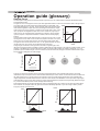
150 mm and above
300 mm
and above
150 mm
and above
Front
Getting Started
- All warnings on the product and in the operating - power source indicated on the label. If you are
instructions should be adhered to.
not sure of the type of power supply to your
- All operating instructions should be followed.
home, consult your product dealer or local
- Place the projector near a wall outlet where the
power company.
plug can be easily unplugged.
- This product is equipped with a three-wire plug.
- Unplug this product from the wall outlet before
7KLVSOXJZLOO¿WRQO\LQWRDJURXQGHGSRZHU
cleaning. Do not use liquid cleaners or aerosol
outlet. If you are unable to insert the plug into
cleaners. Use a damp cloth for cleaning.
the outlet, contact your electrician to install the
- Do not use attachments not recommended by the proper outlet. Do not defeat the safety purpose
product manufacturer as they may be hazardous.
of the grounded plug.
- Do not use this product near water. Do not use
- Power-supply cords should be routed so that
immediately after moving from a low temperature
they are not likely to be walked on or pinched
to high temperature, as this causes condensation, by items placed upon or against them. Pay
ZKLFKPD\UHVXOWLQ¿UHHOHFWULFVKRFNRURWKHU
particular attention to cords at doors, plugs,
hazards.
receptacles, and the point where they exit from
- Do not place this product on an unstable cart,
the product.
stand, or table. The product may fall, causing
- For added protection of this product during a
serious injury to a child or adult, and serious
lightning storm, or when it is left unattended and
damage to the product. The product should be
unused for long periods of time, unplug it from
mounted according to the manufacturer’s
the wall outlet and disconnect the cable system.
instructions, and should use a mount recommend
This will prevent damage to the product due to
ed by the manufacturer.
lightning and power line surges.
PORTABLE CART WARNING
- When the product is used on a
(symbol provided by RETAC) - Do not overload wall outlets, extension cords, or
cart, care should be taken to avoid
convenience receptacles on other equipment as
quick stops, excessive force,
WKLVFDQUHVXOWLQDULVNRI¿UHRUHOHFWULFVKRFN
and uneven surfaces which may
- Never push objects of any kind into this product
cause the product and cart to
through openings as they may touch dangerous
overturn, damaging equipment or
voltage points or short out parts that could result
S3126A
causing possible injury to the
LQD¿UHRUHOHFWULFVKRFN Never spill liquid of
operator.
any kind on the product.
- Slots and openings in the cabinet are provided for - Do not attempt to service this product yourself
ventilation. These ensure reliable operation of the
as opening or removing covers may expose you
product and protect it from overheating. These
to dangerous voltages and other hazards. Refer
openings must not be blocked or covered. (The
DOOVHUYLFHWRTXDOL¿HGVHUYLFHSHUVRQQHO
openings should never be blocked by placing the
- Unplug this product from the wall outlet and
product on bed, sofa, rug, or similar surface. It
should not be placed in a built-in installation such UHIHUVHUYLFHWRTXDOL¿HGVHUYLFHSHUVRQQHO
under the following conditions:
as a bookcase or rack unless proper ventilation is
provided and the manufacturer’s instructions have a) When the power supply cord or plug is damaged.
b) If liquid has been spilled, or objects have fallen on
been adhered to.)
the product.
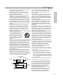
- To allow better heat dissipation, keep a clearance
c) If the product has been exposed to rain or water.
between this unit and its surrounding as shown
d) If the product does not operate normally by
below. When this unit is enclosed in a space of
following the operating instructions. Adjust only
dimensions as shown below, use an air-conditioner
those controls that are covered by the Operation
so that the internal and external temperatures are
Manual, as an improper adjustment of controls may
the same. Overheating can cause damage.
result in damage and will often require extensive
ZRUNE\DTXDOL¿HGWHFKQLFLDQWRUHVWRUHWKHSURGXFW
to normal operation.
e) If the product has been dropped or damaged in any
300 mm
way.
and above
f ) When the product exhibits a distinct change in
performance, this indicates a need for service.
- When replacement parts are required, be sure
the service technician has used replacement
SDUWVVSHFL¿HGE\WKHPDQXIDFWXUHURUZLWK
200 mm
same characteristics as the original part.
and above
8QDXWKRUL]HGVXEVWLWXWLRQVPD\UHVXOWLQ¿UH
electric shock, or other hazards.
- Upon completion of any service or repairs to
this product, ask the service technician to
perform safety checks to determine that the
product is in proper operating condition.
3
㪈
Getting started
- The product should be placed more than one foot
away from heat sources such as radiators, heat
registers, stoves, and other products (including
DPSOL¿HUVWKDWSURGXFHKHDW
- When connecting other products such as VCR’s,
and DVD players, you should turn off the power of
WKLVSURGXFWIRUSURWHFWLRQDJDLQVWHOHFWULFVKRFN
-'RQRWSODFHFRPEXVWLEOHVEHKLQGWKHFRROLQJIDQ
For example, cloth, paper, matches, aerosol cans
or gas lighters that present special hazards when
RYHUKHDWHG
- Do not look into the projection lens while the
LOOXPLQDWLRQODPSLVWXUQHGRQ([SRVXUHRI\RXU
eyes to the strong light can result in impaired
H\HVLJKW
- Do not look into the inside of this unit through
YHQWVYHQWLODWLRQKROHVHWF'RQRWORRNDWWKH
illumination lamp directly by opening the cabinet
ZKLOHWKHLOOXPLQDWLRQODPSLVWXUQHGRQ7KH
illumination lamp also contains ultraviolet rays and
the light is so powerful that your eyesight can be
LPSDLUHG
- Do not drop, hit, or damage the light-source lamp
ODPSXQLWLQDQ\ZD\,WPD\FDXVHWKHOLJKW
VRXUFHODPSWREUHDNDQGOHDGWRLQMXULHV'RQRW
XVHDGDPDJHGOLJKWVRXUFHODPS,IWKHOLJKW
VRXUFHODPSLVEURNHQDVN\RXUGHDOHUWRUHSDLULW
Fragments from a broken light-source lamp may
FDXVHLQMXULHV
- The light-source lamp used in this projector is a
KLJKSUHVVXUHPHUFXU\ODPS%HFDUHIXOZKHQ
GLVSRVLQJRIWKHOLJKWVRXUFHODPS,IDQ\WKLQJLV
XQFOHDUSOHDVHFRQVXOW\RXUGHDOHU
- Do not ceiling-mount the projector to a place which
WHQGVWRYLEUDWHRWKHUZLVHWKHDWWDFKLQJ¿[WXUHRI
the projector could be broken by the vibration,
possibly causing it to fall or overturn, which could
OHDGWRSHUVRQDOLQMXU\
- Use only the accessory cord designed for this
SURGXFWWRSUHYHQWVKRFN
- For health reasons, please take a break of about
5-15 minutes every 30-60 minutes and let your
H\HVUHVW3OHDVHUHIUDLQIURPZDWFKLQJDQ\ 3Dimages when you feel tired, unwell or if you feel
DQ\RWKHUGLVFRPIRUW0RUHRYHULQFDVH\RXVHHD
double image, please adjust the equipment and
VRIWZDUHIRUSURSHUGLVSOD\3OHDVHVWRSXVLQJWKH
unit if the double image is still visible after
DGMXVWPHQW
- Once every three years, please perform an internal
WHVWThis unit is provided with replacement parts
needed to maintain its function (such as cooling
IDQV(VWLPDWHGUHSODFHPHQWWLPHRISDUWVFDQ
vary greatly depending on frequency of use and
WKHUHVSHFWLYHHQYLURQPHQW)RUUHSODFHPHQW
please consult your dealer, or the nearest
DXWKRUL]HG-9&VHUYLFHFHQWHU
:KHQ¿[LQJWKHXQLWWRWKHFHLOLQJ3OHDVHQRWHWKDW
we do not take any responsibility, even during the
warranty period, if the product is damaged due to
XVHRIPHWDO¿[WXUHVXVHGIRU¿[DWLRQWRWKHFHLOLQJ
other than our own or if the installation
4
HQYLURQPHQWRIVDLGPHWDO¿[WXUHVLVQRW
DSSURSULDWH,IWKHXQLWLVVXVSHQGHGIURPWKH
ceiling during use, please be careful in regard to
WKHDPELHQWWHPSHUDWXUHRIWKHXQLW,I\RXXVH
a central heating, the temperature close to the
FHLOLQJZLOOEHKLJKHUWKDQQRUPDOO\H[SHFWHG
- Video images can burn into the electronic com
SRQHQWSDUWV3OHDVHGRQRWGLVSOD\VFUHHQVZLWK
still images of high brightness or high contrast,
such as found in video games and computer
SURJUDPV2YHUDORQJSHULRGRIWLPHLWPLJKW
VWLFNWRWKHSLFWXUHHOHPHQW7KHUHLVQRSUREOHP
ZLWKWKHSOD\EDFNRIPRYLQJLPDJHVHJQRUPDO
YLGHRIRRWDJH
- Not using the unit for a long time can lead to
PDOIXQFWLRQ3OHDVHSRZHULWRQDQGOHWLWUXQ
RFFDVLRQDOO\3OHDVHDYRLGXVLQJWKHXQLWLQD
URRPZKHUHFLJDUHWWHVDUHVPRNHG,WLVLPSRV
sible to clean optical component parts if they are
FRQWDPLQDWHGE\QLFRWLQHRUWDU7KLVPLJKWOHDG
WRSHUIRUPDQFHGHJUDGDWLRQ
3OHDVHZDWFKIURPDGLVWDQFHWKUHHWLPHVWKH
KHLJKWRIWKHSURMHFWHGLPDJHVL]H3HUVRQVZLWK
photosensitivity, any kind of heart disease, or
ZHDNKHDOWKVKRXOGQRWXVH'JODVVHV
- :DWFKLQJ'LPDJHVPLJKWEHFDXVHRILOOQHVV
,I\RXIHHO any change in your physical condition,
please stop watching immediately and consult a
SK\VLFLDQLIQHFHVVDU\
- When watching 3D images, it is recommended
WRWDNHUHJXODUEUHDNV$VWKHOHQJWKDQG
frequency of the required breaks differ for every
person, please judge according to your own
FRQGLWLRQ
,I\RXUFKLOGZDWFKHVZKLOHZHDULQJ'JODVVHV
it should be accompanied by its parents or an
DGXOWJXDUGLDQ7KHDGXOWJXDUGLDQVKRXOGEH
careful to avoid situations where the child’s eyes
might become tired, as responses to tiredness
DQGGLVFRPIRUWHWFDUHKDUGWRGHWHFWDQGLWLV
possible for the physical condition to deteriorate
YHU\TXLFNO\$VWKHYLVXDOVHQVHLVQRW\HWIXOO\
developed in children under the age of 6, please
consult a physician in regard to any problem
FRQFHUQLQJ'LPDJHVLIQHFHVVDU\
- Note that when using the 3D feature, the video
output may appear different from the original
video image due to image conversion on the
GHYLFH
*'2127DOORZDQ\XQTXDOL¿HGSHUVRQ
to install the unit.
%HVXUHWRDVN\RXUGHDOHUWRLQVWDOOWKHXQLW
HJDWWDFKLQJLWWRWKHFHLOLQJVLQFHVSHFLDO
technical knowledge and skills are required
IRULQVWDOODWLRQ,ILQVWDOODWLRQLVSHUIRUPHGE\
DQXQTXDOL¿HGSHUVRQLWPD\FDXVHSHUVRQDO
LQMXU\RUHOHFWULFDOVKRFN
ENGLISH
Safety Precautions (Continued)
For USA and Canada only
Use only the following power cord.
Power cord
The power supply voltage rating of this product is
$&9±$&98VHRQO\WKHSRZHUFRUG
designated by our dealer to ensure Safety and EMC.
Ensure that the power cable used for the projector is
the correct type for the AC outlet in your country.
Consult your product dealer.
Power cord
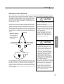
IMPORTANT (Europe only):
The wires in the mains lead on this product are
FRORUHG9HUWHWMDXQHLQDFFRUGDQFHZLWKWKH
following cord:
Green-and-yellow :Earth
:Neutral
Blue
Brown
:Live
As these colors may not correspond with the
colored making identifying the terminals in your
plug, proceed as follows:
The wire which is colored green-and-yellow must
be connected to the terminal which is marked M
with the letter E or the safety earth or colored
green or green-and-yellow. The wire which is
colored blue must be connected to the terminal
which is marked with the letter N or colored black.
The wire which is colored brown must be
connected to the terminal which is marked with the
letter L or colored red.
Getting Started
POWER CONNECTION
POWER CONNECTION
(United Kingdom only)
)RU8QLWHG.LQJGRP)RU(XURSHDQFRQWLQHQW
countries
HOW TO REPLACE THE FUSE:
WARNING:
Do not cut off the main plug from this
equipment.
,IWKHSOXJ¿WWHGLVQRWVXLWDEOHIRUWKHSRZHUSRLQWV
in your home or the cable is too short to reach a
power point, then obtain an appropriate safety
approved extension lead or adapter or consult your
dealer. If nonetheless the mains plug is cut off,
dispose of the plug immediately, to avoid a possible
shock hazard by inadvertent connection to the main
VXSSO\,IDQHZPDLQSOXJKDVWREH¿WWHGWKHQ
follow the instruction given below.
When replacing the fuse, be sure to use only a
FRUUHFWO\UDWHGDSSURYHGW\SHUH¿WWKHIXVHFRYHU
IF IN DOUBT —— CONSULT A COMPETENT
ELECTRICIAN.
Open the fuse compartment with the blade
screwdriver, and replace the fuse.
(* An example is shown in the illustration below.)
WARNING:
Fuse
THIS APPARATUS MUST BE EARTHED.
Dear Customer,
This apparatus is in conformance with the valid European directives and standards regarding
electromagnetic compatibility and electrical safety.
(XURSHDQUHSUHVHQWDWLYHRI-9&.(1:22'&RUSRUDWLRQLV
-9&7HFKQLFDO6HUYLFHV(XURSH*PE+
Postfach 10 05 04
61145 Friedberg
Germany
5
㪈
Getting started
ENGLISH
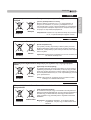
Information for Users on Disposal of Old Equipment and Batteries
[European Union only]
These symbols indicate that equipment with these symbols
should not be disposed of as general household waste. If you
want to dispose of the product o r battery, please consider the
collection systems or fa cilities for appr opriate recycling.
Battery
Products
Notice: The sign Pb below the symbol for batteries indicates that
this battery contains lead.
DEUTSCH
Benutzerinformationen zur Entsorgung alter Geräte und Batterien
[Nur Europäische Union]
Diese Symbole zeigen an, dass derartig gekennzeichnete Geräte
nicht als normaler Haushaltsabfall entsorgt werden dürfen. We
nden Sie sich zur Entsorgung des Produkts oder der Batterie an
die hierfür vorgesehenen Sammelstellen oder Einrichtungen,
damit eine fachgerechte Wiederverwertung möglich ist.
Batterie
Hinweis:'DV=HLFKHQ3EXQWHUKDOEGHV%DWWHULHV\PEROVJLEWDQ
dass diese Batterie Blei enthält.
Produkte
FRANÇAIS
Informations relatives à l’élimination des appareils et des piles usagés, à
l’intention des utilisateurs
[Union européenne seulement]
6LFHVV\PEROHV¿JXUHQWVXUOHVSURGXLWVFHODVLJQL¿HTX¶LOVQH
doivent pas être jetés comme déchets ménagers. Si vous voulez
jeter ce produit ou cette pile, veuillez considérer le système de
collection de déc hets ou les centres de recyclage appropriés.
Pile
1RWL¿FDWLRQ La marque Pb en dessous du symbole des piles
indique que cette pile contient du plomb.
Produits
NEDERLANDS
Informatie voor gebruikers over het verwijderen van oude apparatuur en
batterijen
[Alleen Europese Unie]
Deze symbolen geven aan dat appara tuur met dit symbool niet
mag worden weggegooid als algemeen huishoudelijk afval. Als u
het product of de batterij wilt weggooien, kun t u inzamelsystemen
of faciliteiten voor een geschikte recycling gebruiken.
Batterij
Producten
6
Opmerking: Het teken Pb onder het batterijsymboo l geeft aan
dat deze batterij lood bevat.
ENGLISH
ESPAÑOL / CASTELLANO
[Sólo Unión Europea]
Estos símbolos indican que el equipo con estos símbolos no debe
desecharse con la basura doméstica. Si desea desechar el pro
ducto o batería/pila, acuda a los sistemas o centros de recogida
para que los reciclen debidamente.
Baterías/pilas Atención: La indicación Pb debajo del símbolo de batería/pila
Getting Started
Información para los usuarios sobre la eliminación de baterías/pilas usadas
indica que ésta contiene plomo.
Productos
ITALIANO
Informazioni per gli utenti sullo smaltimento delle apparecchiature e batterie
obsolete
[Solo per l’Unione Europea]
Questi simboli indicano che le apparecchiature a cui sono relativi
QRQGHYRQRHVVHUHVPDOWLWHWUDLUL¿XWLGRPHVWLFLJHQHULFL6HVL
desidera smaltire questo prodotto o questa batteria, prendere in
considerazione i sistem i o le strutture di raccolta appropriati per
il riciclaggio corretto.
Batteria
Prodotti
Nota: Il simbolo Pb sotto il simbolo delle batter ie indica che
questa batteria contiene piombo.
PORTUGUÊS
Informação para os utilizadores acerca da eliminação de equipamento usado e
pilhas
[Apenas União Europeia]
Estes símbolos indicam que o equipamento com estes símbolos
não deve ser eliminado juntamente com o restante lixo doméstico.
Se p retende eliminar o produto ou a pilha, utilize os sistemas de
recolha ou instalações para uma reciclagem apropriada.
Pilha
Aviso: O sinal Pb abaixo do símbolo para pilhas indica que esta
pilha contém chumbo.
Produtos
ǼȁȁǾȃǿȀǹ
ȆȜȘȡȠijȠȡȓİȢȖȚĮIJȘȞĮʌȩȡȡȚȥȘʌĮȜĮȚȠȪİȟȠʌȜȚıȝȠȪțĮȚȝʌĮIJĮȡȚȫȞ
>ǼȣȡȦʌĮȧțȒDzȞȦıȘȝȩȞȠ@
ǹȣIJȐIJĮıȪȝȕȠȜĮȣʌȠįȘȜȫȞȠȣȞȩIJȚȠİȟȠʌȜȚıȝȩȢʌȠȣIJĮijȑȡİȚ
įİȞșĮʌȡȑʌİȚȞĮĮʌȠȡȡȚijșİȓȦȢțȠȚȞȩȠȚțȚĮțȩĮʌȩȡȡȚȝȝĮǼȐȞ
İʌȚșȣȝİȓIJİIJȘȞĮʌȩȡȡȚȥȘĮȣIJȠȪIJȠȣʌȡȠȧȩȞIJȠȢȒĮȣIJȒȢIJȘȢ
ȝʌĮIJĮȡȓĮȢȤȡȘıȚȝȠʌȠȚȒıIJİIJȠıȪıIJȘȝĮʌİȡȚıȣȜȜȠȖȒȢȒ
İȖțĮIJĮıIJȐıİȚȢȖȚĮĮȞȐȜȠȖȘĮȞĮțȪțȜȦıȘ
ȂʌĮIJĮȡȓĮ
ȈȘȝİȓȦıȘȉȠıȪȝȕȠȜȠ3EțȐIJȦĮʌȩIJȠıȪȝȕȠȜȠȝʌĮIJĮȡȓĮȢ
ȆȡȠȧȩȞIJĮ
ȣʌȠįȘȜȫȞİȚȩIJȚȘȝʌĮIJĮȡȓĮʌİȡȚȑȤİȚȝȩȜȣȕįȠ
7
㪈
Getting started
DANSK
Brugerinformation om bortskaffelse af gammelt udstyr og batterier
Batteri
[Kun EU]
Disse symboler angiver, at udstyr med disse symboler ikke må
bortskaffes som almindeligt husholdningsaffald. Hvis du ønsker at
smide dette produkt eller batteri ud, bedes du overveje at bruge
indsamlingssystem et eller steder, hvor der kan ske korrekt gen
brug.
Bemærk: Tegnet Pb under symbolet for batterierne angiver, at
dette batteri indeholder bly.
Produkter
SUOMI
Tietoja vanhojen laitteiden ja akkujen hävittämisestä
[Vain Euroopan unioni]
Nämä symbolit ilmaisevat, että symboleilla merk ittyä laitetta ei
WXOLVLKlYLWWllWDYDOOLVHQNRWLWDORXVMlWWHHQPXNDQD-RVKDOXDWKlYLW
tää tuotteen tai sen akun, tee se hyödyntämällä akkujen
keräyspisteitä tai muita kier rätyspaikkoja .
Akku
Tuotteet
Huomautus: Akkusymbolin alapuolella oleva Pb-merk intä tarkoit
taa, että akku sisältää lyijyä.
SVENSKA
Information för användare gällande bortskaffning av gammal utrustning och
batterier
[Endast den Europeiska unionen]
Dessa symboler indikerar att utrustning med dessa symboler inte
ska hanteras som vanligt hushållsavfall. Om du vill bortsk affa
produkten eller batteriet ska du använda uppsamlingssystem eller
inrättningar för lämplig återvinning.
Batteri
Observera: Märkningen Pb under symbolen för batterier indikerar
att detta batteri innehåller bly.
Produkter
NORSK
Opplysninger til brukere om kassering av gammelt utstyr og batterier
[Bare EU]
Disse symbolene viser at utstyr med dette symbolet, ikke skal
kastes sammen med vanlig husholdningsavfall. Hvis du vil kass
ere dette produkte t eller batteriet, skal du vurdere å bruke innsam
lingssystemene eller andre muligheter for riktig gjenbruk.
Batteri
Produkter
8
Merk: Tegnet Pb under symbolet for batterie r, viser at batteriet
inneholder bly.
ENGLISH
>ɬɨɥɶɤɨɞɥɹȿɜɪɨɩɟɣɫɤɨɝɨɫɨɸɡɚ@
Ⱦɚɧɧɵɟɫɢɦɜɨɥɵɭɤɚɡɵɜɚɸɬɧɚɬɨɱɬɨɨɛɨɪɭɞɨɜɚɧɢɟɧɚ
ɤɨɬɨɪɨɟɨɧɢɧɚɧɟɫɟɧɵɧɟɞɨɥɠɧɵɭɬɢɥɢɡɢɪɨɜɚɬɶɫɹɤɚɤ
ɨɛɵɱɧɵɟɛɵɬɨɜɵɟɨɬɯɨɞɵɉɪɢɧɟɨɛɯɨɞɢɦɨɫɬɢɭɬɢɥɢɡɢɪɨɜɚɬɶ
ɬɚɤɨɟɢɡɞɟɥɢɟɢɥɢɛɚɬɚɪɟɸɨɛɪɚɬɢɬɟɫɶɜɫɩɟɰɢɚɥɶɧɵɣɩɭɧɤɬ
ɫɛɨɪɚɞɥɹɢɯɧɚɞɥɟɠɚɳɟɣɩɟɪɟɪɚɛɨɬɤɢ
Ȼɚɬɚɪɟɹ
ɍɜɟɞɨɦɥɟɧɢɟɇɚɞɩɢɫɶ3Eɩɨɞɫɢɦɜɨɥɨɦɛɚɬɚɪɟɣɭɤɚɡɵɜɚɟɬ
ɂɡɞɟɥɢɹ
ɧɚɬɨɱɬɨɞɚɧɧɚɹɛɚɬɚɪɟɹɫɨɞɟɪɠɢɬɫɜɢɧɟɰ
Getting Started
ɋɜɟɞɟɧɢɹɞɥɹɩɨɥɶɡɨɜɚɬɟɥɟɣɩɨɭɬɢɥɢɡɚɰɢɢɫɬɚɪɨɝɨɨɛɨɪɭɞɨɜɚɧɢɹɢ
ɛɚɬɚɪɟɣ
,QIRUPDFHSURXåLYDWHOHNOLNYLGDFLVWDUpKR]DĜt]HQtDEDWHULt
[Pouze Evropská unie]
7\WRV\PERO\R]QDþXMtåHSURGXNW\VWČPLWRV\PERO\VHQHVPt
OLNYLGRYDWMDNREČåQêRGSDG3RNXGFKFHWHSURGXNWQHEREDWHULL
]OLNYLGRYDWY\XåLMWHVEČUQêV\VWpPQHERMLQp]DĜt]HQtNWHUp]DMLVWt
ĜiGQRXUHF\NODFL
Baterie
Produkty
8SR]RUQČQt=QDþND3ESRGV\PEROHPSUREDWHULH]QDPHQiåH
tato baterie obsahuje olovo.
POLSKI
,QIRUPDFMHGODXĪ\WNRZQLNyZGRW\F]ąFHSR]E\ZDQLDVLĊ]XĪ\WHJRVSU]ĊWXL
baterii
[Tylko kraje Unii Europejskiej]
7HV\PEROHR]QDF]DMąĪHVSU]ĊWXQLHQDOHĪ\Z\U]XFDüUD]HP]
RGSDGDPLJRVSRGDUF]\PL-HĞOLWU]HEDSR]E\üVLĊWHJRSURGXNWX
OXEEDWHULLSURV]ĊVNRU]\VWDü]V\VWHPXRGELRUXOXEXU]ąG]HĔGR
zbió rki odpadów elektronicznych, w celu odpowiedniego ponowne
go ich przetworzenia.
Bateria
Uwaga: 2]QDF]HQLH3E]QDMGXMąFHVLĊSRGV\PEROHPEDWHULL
Produkty
ZVND]XMHĪHWDEDWHULD]DZLHUDRáyZ
MAGYAR
Felhasználói információ az elhasznált be rendezések és akkumulátorok
HOKHO\H]pVpUĘO
[Csak az Európai Unióban]
(]DV]LPEyOXPD]WMHO]LKRJ\DEHUHQGH]pVQHPKHO\H]KHWĘD]
iOWDOiQRVKi]WDUWiVLKXOODGpNN|]p+DPHJV]HUHWQHV]DEDGXOQLD
WHUPpNWĘOYDJ\D]DNNXPXOiWRUWyODNNRUOHJ\HQWHNLQWHWWHOD]
J\ĦMWĘUHQGV]HUUHYDJ\LQWp]PpQ\HNUHDPHJIHOHOĘKDV]QRVtWiV
érdekében.
Akkumulátor Megjegyzés: $]DOiEEL3EV]LPEyOXPKDD]DNNXPXOiWRURQ
Termékek
PHJWDOiOKDWyD]WMHO]LKRJ\D]DNNXPXOiWRUyOPRW
tartalmaz.
9
㪈
Getting started
&ɪɩɫɤɚ
Informacije za korisnike o odlaganju stare opreme i baterija
[Samo u zemljama gde se primenjuje]
Ovi simboli ukazuju da proizvod i baterije sa ovim simbolom ne
VPHMXELWLRGORåHQLNDRQHVRUWLUDQNXüQLRWSDG$NRåHOLWHGDLKVH
UHãLWHPROLPRYDVGDQHXSRWUHEOMDYDWHRELþQXNDQWX]DÿXEUH
Postoje zasebni sistemi za prikupljanje ovakvih proizvoda.
Naznaka: Hemijski simbol Pb ispod simbola za baterije
Baterija
XND]XMHQDWRGDOLEDWHULMDVDGUåLRORYR
Produkt
10
ENGLISH
90 70
Getting Started
7+;&HUWL¿FDWLRQ
7+;&HUWL¿FDWLRQ
(VWDEOLVKHGE\¿OPSURGXFHU*HRUJH/XFDV7+;DLPVWRHQKDQFHWKHUHSURGXFWLRQRI
DXGLRVRXQGDQGYLGHRLPDJHVLQWHQGHGE\¿OPPDNHUVE\VHWWLQJTXDOLW\VWDQGDUGVIRU
FLQHPDYLHZLQJHQYLURQPHQWVDVZHOODVKRPHHQWHUWDLQPHQWV\VWHPV
%DVHGRQWKHNQRZKRZWKDWZHKDYHFXOWLYDWHGRYHUWKHSDVW\HDUVLQDUHDVLQFOXGLQJ
¿OPSURGXFWLRQFLQHPDYLHZLQJHQYLURQPHQWGHVLJQDQGDXGLRYLGHRHGLWLQJZHKDYH
HVWDEOLVKHGDSDUWQHUVKLSZLWK-9&.(1:22'&RUSRUDWLRQWRGHYHORSDQXQSUHFHGHQW
HGKRPHWKHDWHUSURMHFWRUV\VWHP
7KHHPSKDVHVRI7+;&HUWL¿FDWLRQOLHLQWKHYLGHRTXDOLW\DQGVLJQDOSURFHVVLQJ
FDSDELOLW\RISURMHFWRUSURGXFWV-9&SURMHFWRUV'/$;5DQG'/$;5DUHHTXLSSHG
ZLWKWKH7+;PRGHZKLFKLVDEOHWREULQJRXWWKHIXOOSRWHQWLDORIWKHSURMHFWRUZKHQSOD\
LQJPRYLHVRQDODUJHVFUHHQ
5HFHLYHG³7+;''LVSOD\&HUWL¿FDWLRQ´VSHFL¿HGE\7+;/WG
,QDGGLWLRQWKHFHUWL¿FDWLRQVWDQGDUGVZHUHHVWDEOLVKHGZLWKWKHDLPWR³IDLWKIXOO\
UHSURGXFHLPDJHVDWKRPHDFFRUGLQJWRWKHLQWHQWLRQVRIWKH¿OPGLUHFWRU´GXULQJ
SOD\EDFNRI'RU'LPDJHVDQGWKH\DUH³DSURRIRIKLJKGH¿QLWLRQDQGKLJKLPDJH
TXDOLW\´LQGLFDWLQJWKDWDFHUWL¿HGSURGXFWKDVFOHDUHGPRUHWKDQULJRURXVLPDJH
TXDOLW\WHVWVLQFOXGLQJDFFXUDF\RIFRORUUHSURGXFWLRQFURVVWDONYLHZLQJDQJOHVDQG
YLGHRSURFHVVLQJSHUIRUPDQFH
CAUTION
,QRUGHUIRU\RXWRHQMR\'PRYLHV
3OHDVHJHWUHDG\³'JODVVHV´DQGD³'6\QF(PLWWHU´ERWKVROGVHSDUDWHO\
3OHDVHUHDGWKURXJK³6DIHW\3UHFDXWLRQV´5HIHUHQFHSDJHDQGWKHSUHFDXWLRQVLQ
³([SODQDWRU\1RWHVRQWKH'6\VWHP´LQ³2SHUDWLRQ*XLGH*ORVVDU\´
5HIHUHQFHSDJHWR
17KHUHFRPPHQGHGVFUHHQVL]HLVƎDQGWKLVLVOLPLWHGWRIURQW
SURMHFWLRQRQO\
11
㪈
Getting started
For detail information about ISF, please refer web site
http://www.imagingscience.com/
12
90 70
ENGLISH
Contents
Safety Precautions ...........................2
7+;&HUWL¿FDWLRQ 90 70 .................11
Contents .........................................13
Accessories/Optional
Accessories ....................................14
Check the Accessories .............................. 14
Optional Accessories ................................. 14
Controls and features ....................15
Main body - Front ...................................... 15
Main body - Bottom ................................... 15
Main body - Rear ....................................... 16
Main body - About the indicator display ..... 17
Main body - Warning display and
FRQ¿UPDWLRQUHVSRQVH ............................... 18
Main body - Input terminal ......................... 19
How to insert batteries into the remote
control ........................................................ 21
Preparation
About installation ...........................22
IImportant points concerning the
installation ................................................. 22
Installing the Projector and Screen ........... 23
Set Angle ................................................ 23
Shift ....................................................... 23
Fixation of the projector ............................. 24
Screen Size and Projection Distance ........ 25
Effective Range of Remote Control Unit.... 25
Masking the Surrounding Area of
an Image ................................................ 40
Temporary turning-off of the video .......... 41
Adjustment of the keystone correction ... 41
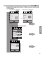
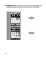
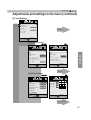
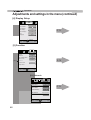
Adjustments and settings
in the menu .....................................42
Structure of the menu hierarchy
(summary) ................................................. 42
Menu operation button .............................. 50
Menu operation procedure ........................ 51
Menu item description ............................... 52
Getting Started
Getting started
Operation guide (glossary) ............74
Maintenance
Replacing the Lamp .......................78
Lamp replacement procedure ................... 78
Resetting lamp Time .................................. 80
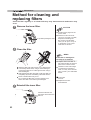
Method for cleaning and
UHSODFLQJ¿OWHUV ...............................82
Others
Troubleshooting .............................84
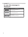
In case this message is
displayed .........................................86
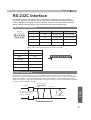
RS-232C Interface ...........................87
56&6SHFL¿FDWLRQV ............................ 87
TCP/IP-connection .................................... 87
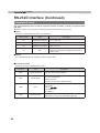
Command Format ..................................... 88
RS-232C Communication Examples ......... 90
Copyright and Caution ...................91
About the connection.....................26
Types of possible input signals
(PC compatible) ......................................... 27
Connection to the unit ............................... 28
Connection of the power cord (provided)
.................................................................. 34
Operation
Basic Operation ..............................36
Basic operation procedures ....................... 36
Frequently used useful functions ............... 38
Setting the Screen Size .......................... 38
About Trademarks and Copyright .............. 91
Caution ...................................................... 91
6SHFL¿FDWLRQV .................................92
Dimensions ................................................ 94
Index ................................................95
CAUTION
About the marks used in this
book
90 Compatible only with DLA-X90R
70 Compatible only with DLA-X70R
X7
30 Compatible only with DLA-X30
13
㪈
Getting started
Accessories/Optional Accessories
Check the Accessories
Lens Cover 30 ..........................................................................1 piece
Remote Control ..........................................................................1 piece
$$$VL]H%DWWHULHVIRURSHUDWLRQFRQ¿UP..................................2 pieces
3RZHU&RUG)RUWKH86PDUNHWP .........................................1 piece
Power Cord For the EU marketP .........................................1 piece
Power Cord For the UK marketP .........................................1 piece
●
Instruction manual (this book, warranty card and other printed material are also included.
Optional Accessories
Please check with your authorized dealer for details.
14
●
Replacement Lamp: PK-L2210U
●
Replacement Filter: PC010661199
●
3D-Glasses: PK-AG1-B , PK-AG2-B
●
3D Synchro Emitter: PK-EM1
ENGLISH
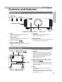
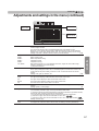
Controls and features
Getting Started
Main body - Front
㽴 Indicator
STANDBY/ON
LAMP
WARNING
㽵 Exhaust Vent
㽲 Lens
㽵 Exhaust
Vent
㽳 Remote receiver (front) Lens cover
㽴 Indicator
㽲 Lens
This is a projection lens. Please do not look
inside during projection.
Please see “About the indicator display” for
details. (Reference page: 17
Lens cover
The lens cover opens/closes when the power
supply is turned on/off.
(Reference page: 66 90 70
㽵 Exhaust Vent
Warm air Àows out in order to cool the interior of
the set. Please do not block the vents.
㽳 Remote receiver (front)
Please aim the remote control at this area when
using it.
(* There is also a remote receiver at the rear.
Main body - Bottom
㽶 Inlets 㽷 Manual button for
lens cover 90 70
㽸 Feet
㽶 Inlets (at 3 points on the rear/
bottom)
In order to cool the inside of the unit, air is let
inside. Do not block or prevent the outÀow of
hot air. Doing so could lead to failure of the unit.
(* There are inlets at two points on the right
and left sides of the rear side.
(Reference page: 16
㽷 Manual operation button of the
lens cover 90 70
The lens cover can be opened when pressed
down.It is used for maintenance and not used
during normal use.
㽸 Feet
The height (0 to 5 mm can be adjusted by
turning the foot.
When the foot is removed, it can be used as the
mounting holes for the ceiling mount bracket.
(Reference page: 24
15
㪈
Getting started
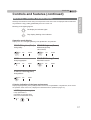
Controls and features (continued)
Main body - Rear
㽶 Inlets
㽺 Lamp Cover
㽶 Inlets 㽹 Input
terminal
㽽 Power input
terminal
㽻 Operation panel
㽼 Light receiving section
of the remote control (rear)
㽹 Input terminal
㽼 Light receiving section of the
remote control (rear)
There is also a terminal other than the input
terminal for video images, such as those used
for controlling or optional equipment. Please see
“About input terminals” for detailed information
about terminals. (Reference page: 19
Please aim the remote control at this section
when using.
(* There is also a light receiving section at
the rear.
㽺 Lamp Cover
When replacing the light source lamp, remove
this cover. (Reference page: 78
㽽 Power input terminal
This is the power input terminal. It is
connected via the supplied power cord.
(Reference page: 34
㽻 Operation panel
See the following illustration “Control panel” for
more details.
■ Operation panel
STANDBY/ON
To turn on/off the power
INPUT
To switch input
OK
7RVHOHFWRUFRQ¿UP
Up button
Right button
Left button
Down button
MENU
To display the menu
16
BACK
To return to the previous menu
ENGLISH
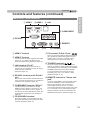
Controls and features (continued)
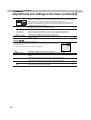
Warnings and indications used during normal operation mode of this unit are displayed with the indicators
for [STAND BY / ON], [LAMP], [WARNING] at the front of this unit.
Meaning of the lighting ¿gures:
The display the indicator lights.
Getting Started
Main body - About the indicator display
They display Àashing of the indicator.
Operation mode display
Displays the color and lighting/Àashing of the [STAND BY / ON] indicator.
STAND BY Light on(Red)
STAND BYLight on(Green)
During standby
While activating the lamp
(about 1 minute)
STANDBY/ON
LAMP
WARNING
STANDBY/ON
LAMP
WARNING
All Off
STAND BY Blinking(Green)
During image projection
When "Hide" is set to ON
STANDBY/ON
LAMP
WARNING
STANDBY/ON
LAMP
WARNING
STAND BY Blinking(Red)
During cool down
STANDBY/ON
LAMP
WARNING
Criterion indication of the lamp replacement
Displays lighting/Àashing of the [LAMP] indicator. Moreover, the [STAND BY / ON] indicator, which shows
the operation mode of this unit, is displayed as described above. (Reference page: 92
LAMP Light on(orange)
Lamp replacement is
near(When accumulated lamp
time has exceeded 2900 hours)
56#0&$;10
.#/2
9#40+0)
17
㪈
Getting started
Controls and features (continued)
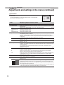
Main body - Warning display and con¿rmation/response
Warning display
You are informed of the contents of warning notices by the (repeated) displays of the [WARNING] and
[LAMP] indicators. Moreover, the [STAND BY / ON] indicator, which shows the operating mode of the unit,
is displayed simultaneously as described above.
Upon activation of the warning mode, the projection is interrupted at the same time for about 60 seconds
and the cooling fan is turned on. Please disconnect the power plug from the electric socket after the
cooling fan has stopped. Subsequently, please perform the following checks and take appropriate
countermeasures.
Lighting/flashing lights
status diagram
56#0&$;10
.#/2
(*)
Blinking
Frequency
Content
1 times
Abnormalities in the power
supply
2 times
Cooling fan stops
3 times
Internal temperature is too
high
4 times
External temperature is
too high
9#40+0)
䇭(red)
Mode
display
.#/2
9#40+0)
䇭 䇭䇭
(orange)䇭䇭(red)
Simultaneous
Mode
Àashing
display
56#0&$;10
.#/2
Mode (orange)
display
9#40+0)
(red)
●
●
1 times
56#0&$;10
Con¿rmation and
countermeasures
2 times
Abnormal electrical circuit
Check that nothing is
blocking the air inlets.
Check that the external
temperature is normal.
Action
Leave the unit until it cools
down.
After that, turn on the power
again.
3 times
4 times
If something is wrong with
the automatic lens cover
●
Lamp does not light up
and unit is unable to
project
●
1 times
2 times
Lamp is turned off during
projection
3 times
Lamp cover is removed
●
Check that an impact shock
has not occurred during
operation.
Check that the lamp
unit and lamp cover are
correctly installed.
Check that nothing is
blocking the auto lens
cover.
Action
Turn on the power again.
If the warning indication is displayed again, please wait for the cooling fan stopped, then pull out the power
plug from the power outlet. Then call your authorized dealer for repair.
(*) If the scheduled time for the replacement of the lamp is exceeded, the light might light up.
18
ENGLISH
Controls and features (continued)
㽲 HDMI 1
㽳 HDMI 2
㽴 LAN
㽶 COMPONENT
Getting Started
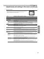
Main body - Input terminal
㽵 RS-232C
㽺 REMOTE
㽷 3D SYNCHRO
㽸 PC
㽲 HDMI 1 Terminal
㽳 HDMI 2 Terminal
You can connect a device equipped with HDMI
output, etc. It is ¿tted to the M3 lock hole.
Screw hole depth 3mm. (Reference page: 29)
㽴 LAN terminal “RJ-45”
This is a LAN-terminal. If one connects an
external PC, it is possible to control this unit by
sending control commands.
(Reference page: 33)
㽵 RS-232C terminal (male D-Sub 9
pin)
This is a RS-232C interface standard terminal.
If one connects an external PC, it is possible to
control this unit. (Reference page: 32)
㽶 COMPONENT terminal “RCAx3”
It is also used as input terminal for analog
RGB (G on Sync) signals, component (Y, Cb,
Cr) signals, DT9 format (Y, Pb, Pr) signals. It
can also be connected with devices, which are
equipped with signal output, etc. (Reference
page: 30)
㽹 TRIGGER
㽸 PC terminal “D-Sub 15 pin”
90 70
This is an input term used for Personal Computer
(PC) signals only (RGB video signals and sync
signals). Use to connect a computer display
output terminal, etc. (Reference page: 31)
㽹 TRIGGER terminal(
)
DC power supply output terminal with DC129,
100mA. It is used for output signals which control
the vacillating screen responding to the SCREEN
TRIGGER. Please note it can cause damage
to your equipment if the connection is done
incorrectly. (Tip = DC +12 9, Sleeve = GND)
(Reference Page: 32, 72)
㽺 REMOTE terminal to “Stereo mini
jack”
In case it is impossible to use the remote control
due to the installation of this unit’s dedicated
BOX or rear projection, one can set up an
external light receiving section. It is used to
connect this external receiver and this unit. There
is no such product as an external light receptor.
Therefore, please consult your authorized -9C
.ENWOOD Corporation. (Reference page: 33)
㽷 3D SYNCHRO terminal
3D synchro emitter: it is connected to the P.EM1 (sold separately) when enjoying 3D video
contents. (Reference page: 31)
19
㪈
Getting started
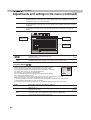
Controls and features (continued)
■ Remote
Control
90 70
90
ON
STAND BY
To turn off the power
This button sequentially
switches 3D formats
(Reference page: 63)
(*) This function cannot be used
when inputting 2D and frame
packing 3D signals
Display the 3D setting
menu(Reference page: 63)
Use this function to sequentially
select focus, zoom and shift
adjustment lens controls.
(Reference page: 65)
To hide the image temporarily
(Reference page: 41)
To turn on the power
INPUT
HDMI 1
HDMI 2
COMP.
3D
FORMAT
3D
SETTING
PC
LENS.
CONTROL
LENS
MEMORY
ANAMO.
HIDE
LIGHT
To select input mode
(Reference page: 36)
This sequentially switches the call up/
save/edit modes of your lens memory
(Reference page: 65)
This sequentially switches anamorphic
modes.(Reference page: 64)
To illuminate buttons on the remote
control for 7 second
To select or con¿rm
To display/close the menu
(Reference page: 50)
BACK
MENU
To return to the previous menu
(Reference page: 50)
PICTURE MODE
This sequentially switches
between users 1-5
To adjust color temperature
To set gamma
FILM
CINEMA
ANIME
NATURAL
STAGE
3D
THX
USER
C.M.D.
To switch picture mode
Color Pro¿le
GAMMA
COLOR
TEMP
COLOR
P.FILE
PIC.
ADJ.
Sequentially switched picture
adjust items, such as contrast and
brightness.The switching items are
not the same for different models, or
different picture modes.
20
ENGLISH
Controls and features (continued)
Control
X7
X7
30
ON
STAND BY
To turn on the power
To turn off the power
This button sequentially switches
3D formats (Reference page: 63)
(*) This function cannot be used
when inputting 2D and frame
packing 3D signals
Display the 3D setting menu
(Reference page: 63)
Use this function to sequentially
select focus, zoom and shift
adjustment lens controls.
(Reference page: 65)
To hide the image temporarily
(Reference page: 41)
INPUT
HDMI 1
HDMI 2
COMP.
3D
FORMAT
3D
SETTING
ANAMO.
LENS.
CONTROL
LENS
MEMORY
LENS AP.
HIDE
LIGHT
To select input mode
(Reference page: 36)
This sequentially switches anamorphic
modes. (Reference page: 64)
This sequentially switches the call up/
save/edit modes of your lens memory
(Reference page: 65)
To adjust Lens Aperture
(Reference page: 57)
To illuminate buttons on the remote
control for 7 second
Getting Started
■ Remote
To select or con¿rm
To display/close the menu
(Reference page: 50)
BACK
MENU
To return to the previous menu
(Reference page: 50)
PICTURE MODE
This sequentially switches
between users 1-5.
To adjust color temperature
To set gamma
FILM
CINEMA
ANIME
NATURAL
STAGE
3D
USER
INFO
C.M.D.
GAMMA
COLOR
TEMP
COLOR
SPACE
To switch picture mode
Display the information menu
(Reference page: 73)
Color Space
PIC.
ADJ.
Sequentially switched picture
adjust items, such as contrast and
brightness.The switching items are
not the same for different models, or
different picture modes.
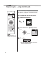
How to insert batteries into the remote control
㽲
●
●
●
㽳
㽴
If the remote control has to be brought closer to the projector to operate, it means that the batteries are
wearing out.
When this happens, replace the batteries. Insert the batteries according to the
marks.
Be sure to insert the
end ¿rst.
If an error occurs when using the remote control, remove the batteries and wait for 5 minutes. Load the
batteries again and operate the remote control.
21
㪉
Preparation
About installation
Important points concerning the installation
Please read the following carefully before the installation of this unit.
Installation environment
Please be careful when using
CAUTION
CAUTION
This unit is a precision device. Therefore, please refrain
from installation or use in the following locations.
Otherwise, it may cause ¿re or malfunction.
Dust, wet and humid locations.
Sooty or cigarette smoke ¿lled locations.
On top of a carpet or bedding, or other soft surfaces.
Locations with high temperatures - as located in direct
sunlight.
Locations with high or low temperatures.
Permissible operating temperature range: +5 º to +35º .
Relative humidity range permissible for operating: 20%
~ 80% (non-condensing) .
Storage temperature tolerance: -10º to +60º.
If the installation of the unit is done in a room with soot
and/or smoke over a longer period, even small amounts
of these substances will affect the device.This unit
cools its optical components, which produce a great
amount of heat, by sucking in air. If the optical circuits
get dirty, this might lead to malfunctions, like the video
images becoming darker or a deterioration of the color
development. Dirt sticking to the optical components
cannot be removed.
This unit uses a projection lamp, which will get hot when
in use. Please refrain from projecting in the following
circumstances.
Otherwise, it might cause ¿re or malfunction.
Projection while lying on its side.
Please avoid projection if the installation of the unit is
done at an excessive angle of more than ± 30 °
. It may
cause harm to the life of the lamp and color shading.
Please avoid projection at a location where the air vents
or exhaust ports might get blocked.
Please be careful to perform
the installation at a certain
distance from walls and
other devices
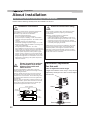
CAUTION
For better heat dissipation, please keep a minimum
distance between this unit and its surroundings as shown
in the following illustration.
Moreover, please open the front of the unit. If there are
any objects in front of the exhaust port, the hot air will
Àow back to the unit and heat it. The hot air Àowing out of
the unit might cause shadows on the screen (heat haze
phenomenon).
Moreover, when it is enclosed in a space as shown in the
following illustration, please make sure that the enclosed
interior has the same temperature as the outside. High
temperatures might lead to failure of the unit.
150 mm and above
300 mm
and above
Please choose a non-uniform cloth material for the screen.
If you choose something uniform, like something with a
checkered pattern, there might be interference with the
pixel array of the D-ILA components. One way to reduce
the interference pattern is to change the size of the screen,
so that it will not be so noticeable.
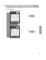
Inclination adjustment
for this unit
How to adjust the vertical angle
Height and inclination of the unit (0 ~ 5mm) can be
adjusted by rotating its feet. Lift the unit and adjust
the four feet.
Stand
300 mm
and above
150 mm
and above
Front
200 mm
and above
Extend
22
Contract
ENGLISH
About installation (Continued)
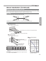
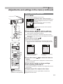
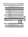
Installing the Projector and Screen
While installing, please place this unit and the screen perpendicular to each other. Failing
to do so may increase trapezoidal distortion. (Reference page: 36, 52)
Set Angle
Preparation
●
30°
30°
30°
30°
The angle range which can be set for this unit is ±30°.
Malfunctions may occur if the angle is not set within the above-mentioned range.
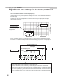
Shift
■ Left/Right position
䇭 (*)㩷0% up/down position (center)
Approximately 34% (maximum) of the projected image
Approximately 34% (maximum) of the projected image
■ Up/Down position
䇭 (*)㩷0% left/right position (center)
■ Lens shift movement
Approximately 80%
(maximum) of the projected
image
Approximately 80%
(maximum) of the
projected image
Lens shift correlation chart:
Vertical lens shift(%)
range
90
80
70
60
50
40
Left-Right Shift(%)
0%
10%
20%
30%
34%
30
Up-Down Shift(%)
80%
66%
47%
18%
0%
20
●
●
Maximum Up-Down shift varies with the amount of Left-Right shift.
Likewise, maximum Left-Right shift varies with the amount of UpDown shift.
The values on the chart are intended to act as a guide. Use them
for reference during installation.
10
Lens movability
range
0 10 20 30 40
Horizontal lens shift(%)
23
㪉
Preparation
About installation (Continued)
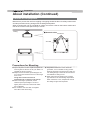
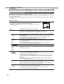
Fixation of the projector
Measures to prevent the unit from toppling or dropping should be taken for safety reasons and
accident prevention during emergencies including earthquakes.
When mounting this unit on a pedestal or ceiling, remove the 4 feet on the bottom surface and
use all the 4 screw holes (M5 screws) to mount.
Ceiling
■ Bottom Surface
4 locations
Air inlets
Precautions for Mounting
●
●
●
●
24
Special expertise and techniques are required for
mounting this unit. Be sure to ask your dealer or a
specialist to perform mounting.
Depth of the screw holes (screw length) is 23
mm. Use screws shorter than 23 mm but longer
than 13 mm.
Using other screws will result in
malfunctioning or cause the unit to drop.
When mounting to a pedestal, ensure
VXI¿FLHQWVSDFH(foot height of 10 mm or
higher) around the unit so that the air inlets
are not blocked.
Do not tilt this unit more than ±5 degrees
from side to side when using.
●
●
Regardless whether the unit is still under
guarantee, -9&LVQRWOLDEOHIRUDQ\SURGXFW
damage caused by mounting the unit with non-9&FHLOLQJ¿WWLQJVRUZKHQWKHHQYLURQPHQWLV
not suitable for ceiling-mount.
When using the unit hanging from a ceiling,
pay attention to the surrounding temperature.
When a heater is in use, temperature around
the ceiling is higher than expected.
ENGLISH
About installation (Continued)
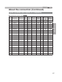
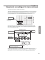
Screen Size and Projection Distance
Determine the distance from the lens to the screen to achieve your desired screen size.
This unit uses a 2.0x power zoom lens for projection.
■ Relationship Between Projection Screen Size and Projection Distance
Approximate Projection
DistanceW(Wide) to T(Tele)
60"
(Approx. 0.7, 1.3m)
Approx.1.78m to
Approx.3.66m
70"
(Approx.0.9, 1.5m)
Approx.2.09m to
Approx.4.28m
80"
(Approx.1.0, 1.8m)
Approx.2.40m to
Approx.4.89m
90"
(Approx.1.1, 2.0m)
Approx.2.70m to
Approx.5.51m
100"
(Approx.1.2, 2.2m)
Approx.3.01m to
Approx.6.13m
110"
(Approx.1.4, 2.4m)
Approx.3.31m to
Approx.6.75m
120"
(Approx.1.5, 2.7m)
Approx.3.62m to
Approx.7.36m
130"
(Approx.1.6, 2.9m)
Approx.3.92m to
Approx.7.98m
Projection Screen Size
(Height, Width)
Aspect Ratio 16:9
Approximate Projection
DistanceW(Wide) to T(Tele)
140"
(Approx.1.7, 3.1m)
Approx.4.23 m to
Approx.8.60m
150"
(Approx.1.9, 3.3m)
Approx.4.53m to
Approx.9.22m
160"
(Approx.2.0, 3.5m)
Approx.4.84m to
Approx.9.84m
170"
(Approx.2.1, 3.8m)
Approx.5.14m to
Approx.10.45m
180"
(Approx.2.2, 4.0m)
Approx.5.45m to
Approx.11.07m
190"
(Approx.2.4, 4.2m)
Approx.5.75m to
Approx.11.68m
200"
(Approx.2.5, 4.4m)
Approx.6.06m to
Approx.12.30m
Preparation
Projection Screen Size
(Height, Width)
Aspect Ratio 16:9
Effective Range of Remote Control Unit
This unit
■ When directing the remote control toward this
unit.
●
●
30°
When aiming the remote control towards the
remote sensor on this unit, ensure that the
distance to the sensor in front or at the rear of
this unit is within 7 m.
30°
20°
20°
If the remote control fails to work properly, move
closer to this unit.
Remote control
■ :KHQUHÀHFWLQJRIIDVFUHHQ
● Ensure
that the total of distance A between this
unit and screen and distance B between remote
control and screen is within 7 m.
30°
20°
A
20°
●
$VWKHHI¿FLHQF\RIVLJQDOVUHÀHFWHGIURPWKH
remote control unit differ with the type of screen
used, operable distance may decrease.
30°
This unit
B
Screen
Remote control
25
㪉
Preparation
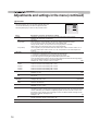
About the connection
Types of possible input signals
Analog 9ideo Input Format
signals
480i, 480p, 576i, 576p, 720p/50Hz, 720p/60Hz,
1080i/50Hz, 1080i/60Hz
Digital 9ideo Input Format
signals
480i, 480p, 576i, 576p, 720p/50Hz, 720p/60Hz,
1080i/50Hz, 1080i/60Hz,1080p/24Hz,
1080p/50Hz, 1080p/60Hz
frame pack method
3D
signal
720p/50Hz, 720p/60Hz, 1080p/24Hz, 1080i/50Hz, 1080i/60Hz
1080i/60Hz, 1080p/60Hz, 1080i/50Hz, 1080p/50Hz, 1080p/24Hz,
side by side method 720p/50Hz, 720p/60Hz
top and down method 720p/50Hz, 720p/60Hz, 1080p/24Hz
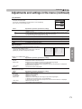
● PC
26
signal (HDMI)
No. of
dot CL. Total No. Total No. effective
of
dots
of
lines
[MHz]
dots
[dot]
[line]
[dot]
No. of
effective
lines [line]
No.
Designation
Resolution
fh
[kHz]
fv
[Hz]
1
9GA 60
640 X 480
31.500
60.000
25.200
800
525
640
480
2
9GA 59.94
640 X 480
31.469
59.940
25.175
800
525
640
480
3
S9GA 60
800 X 600
37.879
60.317
40.000
1,056
628
800
600
4
XGA 60
1024 X 768
48.363
60.004
65.000
1,344
806
1,024
768
5
WXGA 60
1280 X 768
47.760
60.000
79.998
1,675
796
1,280
768
6
WXGA +60
1440 X 900
55.919
59.999 106.470
1,904
932
1,440
900
7
SXGA 60
1280 X 1024
63.981
60.020 108.000
1,688
1,066
1,280
1,024
8
WSXGA +60
1680 X 1050
65.222
60.002 147.140
2,256
1,087
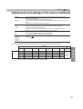
1,680
1,050
9
WUXGA 60
1920 X 1200
74.038
59.95
2,080
1,235
1,920
1,200
154.000
ENGLISH
About the connection (Continued)
Types of possible input signals (PC compatible)
● PC
signal (D-sub 3-lines 15 pins) 90 70
No.
Designation
Resolution
fh
[kHz]
fv
[Hz]
1
9GA 60
640 X 480
31.500
60.000
25.175
800
525
640
480
2
9GA 72
640 X 480
37.900
72.000
31.500
832
520
640
480
3
9GA 75
640 X 480
37.500
75.000
31.500
840
500
640
480
4
9GA 85
640 X 480
43.300
85.000
36.000
832
509
640
480
5
S9GA 56
800 X 600
35.200
56.000
36.000
1024
625
800
600
6
S9GA 60
800 X 600
37.900
60.000
40.000
1056
628
800
600
7
S9GA 72
800 X 600
48.100
72.000
50.000
1040
666
800
600
8
S9GA 75
800 X 600
46.900
75.000
49.500
1056
625
800
600
9
S9GA 85
800 X 600
53.700
85.000
56.250
1048
631
800
600
10
XGA 60
1024 X 768
48.400
60.000
65.000
1344
806
1024
768
11
XGA 70
1024 X 768
56.500
70.000
75.000
1328
806
1024
768
12
XGA 75
1024 X 768
60.000
75.000
75.750
1312
800
1024
768
13
XGA 85
1024 X 768
68.700
85.000
94.500
1376
808
1024
768
14
WXGA 60
1280 X 768
47.760
60.000
79.998
1675
796
1280
768
15
WXGA+ 60
1440 X 900
55.919
59.999
106.470
1904
932
1440
900
16
SXGA 60
1280 X 1024 64.000
60.000
108.000
1688
1066
1280
1024
17
SXGA+ 60
1400 X 1050 63.981
60.020
108.000
1688
1066
1400
1050
Total
dot CL. Total No. No. of
of dots lines
[MHz]
[dot]
[line]
No. of
No. of
effective
effective
dots
lines [line]
[dot]
WSXGA+ 60
1680 X 1050 65.222
60.002
147.140
2256
1087
1680
1050
19
1920x1080 60
1920 X 1080 67.500
60.00
148.500
2200
1125
1920
1080
20
MAC13"
640 X 480
35.000
66.667
30.240
864
525
640
480
21
MAC16"
832 X 624
49.107
75.087
55.000
1120
654
832
624
22
MAC19"
1024 X 768
60.241
74.927
80.000
1328
804
1024
768
Preparation
18
27
㪉
Preparation
About the connection (Continued)
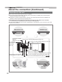
Connection to the unit
●
Do not turn on the power until connection is complete.
●
The connection procedures differ according to the device used. For details, refer to the instruction
manual of the device to be connected.
●
This device is used for image projection. Connect to an audio output device such as ampli¿er and
speaker for audio output from the connected device.
●
The images may not be displayed depending on the devices and cables to be connected.
For HDMI cable (sold separately), only use one that is HDMI-approved.
●
It may not be possible to connect to this unit depending on the dimension of the connector cover of the
cables to be connected.
BD/DVD Recorder
To connect via HDMI
terminal
BD/DVD Player
Connection by LAN terminal (Reference page: 33)
(Reference page: 29)
To connect RS232C terminal
(Reference
page: 32)
To connect via video terminal (Reference page: 30)
STANDBY/ON
INPUT
1
HDMI
2
OK
RS-232-C
3D
SYNCHRO
CR/PR CB/PB
PC
Y
REMOTE
TRIGGER CONTROL
MENU
BACK
Connection by REMOTE terminal (Reference page: 33)
Connection by 3D SYNCHRO
terminal (Reference page: 31)
PC
28
To connect via Trigger terminal (Reference page: 32)
To connect via PC terminal (Reference page: 31) 90 70
VCR and
camcorder
ENGLISH
About the connection (Continued)
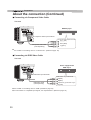
■ Connecting
via HDMI Cable
This unit
Notebook PC
STANDBY/ON
INPUT
1
HDMI
2
OK
3D
SYNCHRO
PC
Y
BD/DVD recorder
REMOTE
TRIGGER CONTROL
MENU
BACK
HDMI 1 input terminal
HDMI 2 input terminal
Preparation
CR/PR CB/PB
RS-232-C
HDMI output terminal
HDMI cable (sold separately)
●
If noise is produced, take PCs (Notebook PC) away from this unit.
●
For a transmission bandwidth in compliance with the HDMI standard, a 340MHz cable is recommended.
In case a cable is used for transmission bandwidth of 75MHz, it is recommended to choose 1080i or less
for the transmitting equipment.
●
If the video is not displayed, try to reduce the length of the cable or lowering the resolution of the video
transmitting equipment.
■ Connecting
via HDMI-DVI Conversion Cable
This unit
Desktop computer
STANDBY/ON
INPUT
1
HDMI
2
OK
RS-232-C
3D
SYNCHRO
CR/PR CB/PB
PC
Y
REMOTE
TRIGGER CONTROL
MENU
BACK
HDMI 1 input terminal
HDMI 2 input terminal
DVI output terminal
HDMI-DVI conversion cable
(sold separately)
●
If noise is produced, take PCs (desktop computer) away from this unit.
●
If the video is not displayed, try to reduce the length of the cable or lowering the resolution of the video
transmitting equipment.
29
㪉
Preparation
About the connection (Continued)
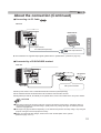
■ Connecting
via Component Video Cable
This unit
STANDBY/ON
INPUT
OK
BD/DVD player
MENU
1
HDMI
BACK
2
CR/PR CB/PB
RS-232-C
3D
SYNCHRO
PC
Y
REMOTE
TRIGGER CONTROL
To component video input terminals
Component video output terminals
CR/PR (red)
CB/PB (blue)
Component video cable
(sold separately)
●
Y (green)
Set “COMP.” in the setting menu to “Y Pb/Cb Pr/Cr”. (Reference page: 60)
■ Connecting
via RGB Video Cable
This unit
STANDBY/ON
INPUT
1
HDMI
Device equipped with
RGB output
2
OK
RS-232-C
3D
SYNCHRO
CR/PR CB/PB
PC
Y
REMOTE
TRIGGER CONTROL
To RGB video input terminals
MENU
BACK
RGB video output terminals
R(Red)
RGB video cable
(sold separately)
30
B(Blue)
G(Green) (Includes sync
signals)
●
Set “COMP.” in the setting menu to “RGB”. (Reference page: 60)
●
For information on compatible input signals, see “Speci¿cations”. (Reference page: 92)
ENGLISH
About the connection (Continued)
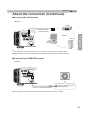
■ Connecting
via PC Cable
90 70
This unit
STANDBY/ON
Notebook PC
INPUT
1
HDMI
2
OK
CR/PR CB/PB
RS-232-C
3D
SYNCHRO
Y
REMOTE
TRIGGER CONTROL
PC
BACK
To PC input terminal
PC cable(sold separately)
●
VGA output terminal
Preparation
MENU
For information on supported input signals, please refer to 6SHFL¿FDWLRQV . (Reference page: 92)
■ Connected
by a 3D SYNCHRO terminal
This unit
STANDBY/ON
INPUT
1
HDMI
2
OK
RS-232-C
3D
SYNCHRO
CR/PR
PC
CB/PB
3D-glasses
Y
REMOTE
TRIGGER CONTROL
MENU
BACK
3D synchro emitter
●
3D synchro emitter: This is a dedicated terminal for PK-EM1 (sold separately).
●
The PK-EM1 infrared sometimes affects other infrared communication devices.
●
3D glasses (PK-AG1-B, PK-AG2-B) is an optional device, and is not included in the 3D synchro emitter.
CAUTION
● Note that converting 2D images to 3D ones using the 3D feature of this product, and playing them for
commercial purposes or for broadcasting in public places may infringe the rights of authors protected
under the copyright laws.
● 3D images may appear different depending on the ambient temperature and lamp usage. Stop using the
projector if images cannot be projected correctly.
● Before you watch 3D video images, make sure to read "3D description of the system".
(Reference page: 75 to 77)
31
㪉
Preparation
About the connection (Continued)
■ Connecting
via Trigger Cable
This unit
STANDBY/ON
INPUT
1
HDMI
2
Screen
OK
RS-232-C
3D
SYNCHRO
CR/PR
CB/PB
Y
TRIGGER
PC
To Trigger output terminal
REMOTE
CONTROL
MENU
BACK
Trigger cable
(sold separately)
㩷㩷㩷㩷㩷
●
●
●
●
●
Trigger input terminal
( Φ 3.5)
CAUTION
Do not supply the power to the other devices.
Do not connect audio terminals of the other devices such as headphones etc. Otherwise, this may
cause a malfunction of the other devices or injury.
Using beyond the rated value will cause malfunction.
Exercise adequate caution to prevent short circuit as the trigger terminal outputs a voltage of 12V.
The default is set to "No output". Please set it under the item "Trigger" of menu [5] "Function". (Reference
page: 72)
■ Connected
by RS-232C connection cable
This unit
STANDBY/ON
INPUT
1
HDMI
2
OK
CR/PR CB/PB
3D
SYNCHRO
PC
Y
REMOTE
TRIGGER CONTROL
MENU
BACK
RS-232C
RS-232C connection cable (sold separately)
32
terminal
ENGLISH
About the connection (Continued)
■ Connected
by LAN terminal
This unit
HUB
connection cable
(sold separately)
STANDBY/ON
INPUT
1
HDMI
2
Network
OK
Y
Server
3D
SYNCHRO
PC
REMOTE
TRIGGER CONTROL
MENU
BACK
●
The network is used to control the unit. It is not used for transmission of the video signal.
●
Please contact your network administrator for questions concerning the network connection.
■ Connected
Preparation
CR/PR CB/PB
RS-232-C
by a REMOTE terminal
This unit
STANDBY/ON
INPUT
1
HDMI
2
OK
RS-232-C
3D
SYNCHRO
CR/PR CB/PB
PC
Y
REMOTE
TRIGGER CONTROL
MENU
BACK
connection cable(sold separately)
●
External infrared sensor
(sold separately)
For an external infrared sensor and connecting cable, please contact your dealer.
33
㪉
Preparation
About the connection (Continued)
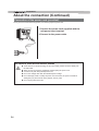
Connection of the power cord (provided)
Once you have connected the equipment, connect the projector power cord.
STANDBY/ON
INPUT
1
HDMI
2
OK
RS-232-C
3D
SYNCHRO
CR/PR CB/PB
PC
1 Connect the power cord supplied with the
unit power input terminal
Y
2 Connect to the power outlet
REMOTE
TRIGGER CONTROL
MENU
BACK
1
Power Cord
(Supplied)
2
Be carful to avoid ¿re and electric shocks
CAUTION
34
●
As the amount of electrical energy for this unit is large, please connect it directly into
the wall outlet.
●
When you are not using the equipment, please unplug the power cord.
●
Connect it only with the provided power cord.
●
Do not use voltage other than the indicated power voltage.
●
Do not damage, break or modify the power cord. Moreover, the power cord will be
damaged if you place it under heavy objects, heat or pull it.
●
Do not unplug with wet hands.
ENGLISH
MEMO
Preparation
35
㪊
Operation
Basic Operation
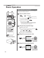
Basic operation procedures
6
1
STAND BY
ON
Once you have ¿nished the basic setup, the unit can normally be
used just with the following operations.
1
Turn on power source
ON
INPUT
HDMI 1
HDMI 2
COMP.
3D
FORMAT
3D
SETTING
PC
STANDBY/ON
2
Light on (Green)
●
LENS.
CONTROL
LENS
MEMORY
on the power. (Reference page: 16)
ANAMO.
●
HIDE
LIGHT
2
BACK
The lens cover will be opened. 90 70
Remove the lens cover. X7
30
(*) Be sure to remove the lens cover when you use the
product Projection without removing the lens cover
may cause the product to malfunction.
3
4
5
MENU
button on the unit to turn
You can also press the
Choose the projected image
PICTURE MODE
FILM
CINEMA
ANIME
NATURAL
STAGE
3D
THX
USER
C.M.D.
1 Select input mode
●
You can also select the input mode by pressing the
button on the unit. (Reference page: 16)
HDMI 1
GAMMA
COLOR
TEMP
COLOR
P.FILE
HDMI 2
COMP.
INPUT
PC
PIC.
ADJ.
2 Play back the selected device
90 70
X7
30 : The same button
arrangement is used for the
operations in this explanation.
3
Adjust the zoom (screen size)
Lens Control
LENS
9#40+0)
.#/2 56#0&$;10
Zoom
Select Back
BACK
Operate
Exit
MENU
4
Adjust accordingly
by pressing the up/
down buttons
Adjust the focus (focal point)
Lens Control
LENS
Focus
Exit
MENU
36
Select Back
BACK
Operate
Adjust accordingly
by pressing the
up/down buttons
ENGLISH
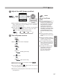
5
Adjust the shift (image position)
Lens Control
MEMO
Shift
LENS
Select Back
BACK
Operate
●
After adjusting the image position, it may be necessary to
select “Pixel Adjust” from the Settings menu “Installation”.
(Reference page: 66 to 67)
●
Every time the LENS button is pressed, the adjustment
item will be switched among “Focus”, “Zoom” and “Shift”.
)RFXV
LENS
=RRP
The Cool Down mode is a
function to cool down the lamp
for approximately 60 seconds
after projection is complete.
This function prevents the
internal parts of the unit from
deformation or damage due to
overheating of the lamp. It also
prevents lamp blowout and
premature shortening of lamp
life.
●
During Cool Down mode, the
[STANDBY/ON] indicator blinks
in red.
●
After the Cool Down mode is
complete, the unit automatically
returns to standby mode.
●
Do not pull out the power plug
during Cool Down mode. This
may shorten the lamp life and
cause a malfunction.
●
The slide cover will not close
if the [Slide Cover] is set to
[Open] in the [3. Setup] [3-1. Lens Control] menu.
(Reference page: 66)
Turn off power source
While a confirmation screen is displayed
STAND BY
Operation
●
6KLIW
STAND BY
About Cool Down
mode
It can also be switched with the button.
OK
6
Adjust accordingly
by pressing the
up/down/left/right
buttons
STAND BY/ON
Blinking (Red Lamp)
Cool Down mode
STAND BY/ON
Light on (Red Lamp)
●
●
When power off, the lens cover will be closed. 90 70
30
Set the lens cover. X7
●
You can also press the
button on the unit to turn off
the power. (Reference page: 16)
●
Pull out the power plug when the unit will not be used for a
prolonged time.
37
㪊
Operation
Basic Operation (continued)
Frequently used useful functions
ON
STAND BY
You can change the screen size of the projected image or
hide the surrounding area of an image for which quality at the
outer area has deteriorated.
A
B
INPUT
C
HDMI 1
HDMI 2
COMP.
3D
FORMAT
3D
SETTING
PC
LENS.
CONTROL
LENS
MEMORY
ANAMO.
D
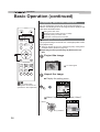
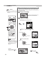
A Setting the Screen Size
The projected image can be set to a most appropriate screen
size (aspect ratio).
●
HIDE
LIGHT
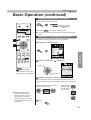
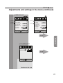
Setting the Screen Size
Masking the Surrounding Area of an Image
Temporary turning-off of the video
Adjustment of the keystone correction
When PC signals are input, the “Aspect(Computer)” setting will be
available instead. (Reference page: 60)
■ Input Image and Projected Image by Different Screen
Size
A
1
Project the image
BACK
MENU
PICTURE MODE
FILM
CINEMA
ANIME
NATURAL
STAGE
3D
THX
USER
C.M.D.
4:3 video signal
GAMMA
COLOR
TEMP
COLOR
P.FILE
PIC.
ADJ.
2
Aspect the image
㩷 1 㩷Display the setting menu
90 70
X7
30 : The same button
arrangement is used for the
operations in this explanation.
Picture Adjust
Picture Mode
Color Profile
Color Temp.
Gamma
Dark/Bright Level
Picture Tone
Contrast
Brightness
Color
Tint
MENU
Natural
Video
Normal
0
0
0
0
Reset
Advanced
Operate
Exit
MENU
Back
BACK
Select
2 㩷Select “Input Signal”
㩷
“Aspect (Video)”
㽲 Select
Input Signal
HDMI
COMP.
PCޓ
Picture Position
㽳 Confirm
Aspect (Video)
4:3
Mask
off
Progressive
Auto
3D Setting
Operate
Exit
MENU
38
4:3
16:9
Custom
Select
Back
BACK
ENGLISH
3 㩷Set a Aspect value
㽲 Select
Input Signal
HDMI
COMP.
PCޓ
Picture Position
Aspect (Video)
㽳 Confirm
16:9
4:3
Mask
off
Progressive
Auto
16:9
Custom
3D Setting
Operate
Exit
MENU
Select
Back
BACK
Example:
When the “Aspect” value is
changed from “4:3” “16:9”
3
To end
MENU
●
Depending on the input image, selecting “4:3” may result in a
vertically stretched image, while selecting “16:9” provides you
with the most appropriate screen size.
When there is 3D signal input, the ratio is ¿xed to “16:9”.
Operation
●
39
㪊
Operation
B Masking the Surrounding Area of an Image
MEMO
●
Masking is available only
when high definition images
are input.
Images for which quality at the outer area has deteriorated
can be projected by masking (hiding) the surrounding area of
the projected image.
1
Project the image
Image for which quality at the
outer area has deteriorated.
ON
STAND BY
2
Mask the image
INPUT
HDMI 1
HDMI 2
COMP.
3D
FORMAT
3D
SETTING
PC
LENS.
CONTROL
LENS
MEMORY
ANAMO.
㩷 1 㩷Display the setting menu
Picture Adjust
Picture Mode
Color Profile
Color Temp.
Gamma
Dark/Bright Level
Picture Tone
Contrast
Brightness
Color
Tint
MENU
HIDE
LIGHT
B
Natural
Video
Normal
0
0
0
0
Reset
Advanced
Operate
Exit
MENU
BACK
MENU
2 㩷Select
㩷
Select
“Input Signal”
Back
BACK
“Mask”
PICTURE MODE
FILM
CINEMA
ANIME
Input Signal
㽲 Select
NATURAL
STAGE
HDMI
3D
COMP.
PCޓ
THX
GAMMA
USER
COLOR
TEMP
COLOR
P.FILE
Picture Position
C.M.D.
PIC.
ADJ.
Aspect (Video)
㪈㪍㪑㪐
Mask
Off
Progressive
Auto
3D Setting
㽳 Confirm
Operate
Exit
MENU
90 70
X7
30 : The same button
arrangement is used for the
operations in this explanation.
(*) When there is a 3D input
signal, adjustment is not
possible.
㪉㪅㪌㩼
㪌㩼
Off
Custom
Back
BACK
Select
3 㩷Set a mask value
㽲 Select
Input Signal
HDMI
COMP.
PCޓ
Picture Position
㽳 Confirm
Aspect (Video)
㪈㪍㪑㪐
㪉㪅㪌㩼
㪌㩼
㪌㩼
Mask
Progressive
3D Setting
Off
Custom
Auto
Operate
Exit
MENU
Select
Back
BACK
Example:
When the “Mask” value is
changed from “Off” “5%”
3
To end
MENU
40
ENGLISH
Basic Operation (continued)
C Temporary turning-off of the video
You can hide the image temporarily.
HIDE
ON
STAND BY
Green light blinks
when the image is
hidden.
INPUT
HDMI 2
COMP.
●
Press the
3D
FORMAT
3D
SETTING
PC
●
The power cannot be turned off when the image is temporarily
hidden.
LENS.
CONTROL
LENS
MEMORY
ANAMO.
HDMI 1
C
HIDE
LIGHT
HIDE
button again to display image.
D Adjustment of the keystone correction
In regards to the projection plane, any occurring keystone distortion
is adjusted in case the installation location is inclined.
㩷 1 㩷Display the setting menu
D
Picture Adjust
Picture Mode
BACK
MENU
MENU
PICTURE MODE
FILM
STAGE
ANIME
Video
Normal
0
0
0
0
Reset
Advanced
3D
Operate
Exit
MENU
THX
GAMMA
USER
COLOR
TEMP
COLOR
P.FILE
C.M.D.
PIC.
ADJ.
2 㩷Select “Installation´
㩷
Operation
NATURAL
CINEMA
Natural
Color Profile
Color Temp.
Gamma
Dark/Bright Level
Picture Tone
Contrast
Brightness
Color
Tint
Select
Back
BACK
“.eystone´
Installation
Lens Control
㽲 Selec
Pixel Adjustޓ
Installation Style
90 70
X7
30 : The same button
arrangement is used for the
operations in this explanation.
Front
Keystone
Anamorphic
Off
Screen Adjust
Black Level
㽳 Confirm
Operate
Exit
MENU
3 㩷Adjusts
㩷
Select
Back
BACK
keystone correction
If one presses the cursor (vertical and horizontal arrows) in the
keystone correction mode, the keystone distortion can be adjusted.
Adjust horizontal distortion with the
cursors for left and right.
●
When there is a 3D input
signal, adjustment is not
possible. Moreover, even if
the keystone correction is
adjusted, keystone correction
is removed when there is a 3D
input signal.
Adjust vertical
distortion with
the cursors for
up and down.
㩷
4 㩷Exit
MENU
41
㪊
Operation
Adjustments and settings in the menu
Structure of the menu hierarchy (summary)
The Menu of this unit is organized as follows. As this is only a brief guideline, items, which might not be
displayed due to certain settings, are still displayed in the illustration. Moreover, in regard to , it shows
countermeasures for all kinds of devices, but there the values for setting and adjustment might be different.
See “Description of menu items” (Reference: Since 52 and following) for details. It can be moved to
subscreens used for adjustment, even for items that do not feature submenus.
[1] Picture Adjust
90 70
30
Picture Adjust
Picture Adjust
Picture Mode
[1-1]
[1-2]
Color Profile
Color Temp.
Gamma
Dark/Bright Level
Picture Tone
Contrast
Brightness
Color
Tint
Natural
Picture Mode
Video
Contrast
Brightness
Color
Tint
Color Temp.
Gamma
Advanced
Normal
[1-1]
0
0
[1-2]
0
0
0
0
0
ޓ6500K
Normal
0
Reset
Reset
Advanced
Operate
Exit
MENU
Natural
MENU
BACK
Select
Operate
Exit
Back
Back
BACK
Select
P. 52
[1-1] Color Temp.
Picture Adjust
Color Temp.
-
Preset
Gain Red
Gain Green
Gain Blue
Offset Red
Offset Green
Offset Blue
Custom
Custom
Custom
0
0
0
0
P. 55
0
0
Reset
Exit
MENU
Operate Back
Select
Continue to the next
42
BACK
ENGLISH
Adjustments and settings in the menu (continued)
[1-2] Advanced
30
90 70
Picture Adjust
Picture Adjust
Advanced
Advanced
[1-2-1]
[1-2-2]
[1-2-3]
Sharpness
NR
Custom Gamma
Color Management
User Name Edit
Clear Motion Drive
CMD Demo
Lens Aperture
Lamp Power
[1-2-2]
1HH
1HH
0
0QTOCN
Operate
Exit
MENU
[1-2-1]
MENU
BACK
5VCPFCTF
1HH
0
0QTOCN
Operate
Exit
Back
Select
Sharpness
NR
Color Space
Custom Gamma
User Name Edit
Clear Motion Drive
CMD Demo
Lens Aperture
Lamp Power
Back
BACK
Select
P. 56
Operation
[1-2-1] Sharpness
Picture Adjust
Sharpness
Sharpness
25
Detail Enhance
0
P. 58
Operate
Exit
MENU
Select
Back
BACK
Continue to the next
43
㪊
Operation
Adjustments and settings in the menu (continued)
[1-2-2] Custom Gamma
Picture Adjust
Custom Gamma
Custom
Custom
Custom
Correction Value
1023
White
Red
Green
Blue
512
Normal
P. 58
Reset
0
Exit
50
Operate Back
MENU
BACK
Select
[1-2-3] Color Management
90
70
Picture Adjust
Color Management
1HH
Pause
Custom
Custom
Custom
Off
P. 59
Reset
Exit
MENU
44
Color Selection
0
Axis Position
0
Hue
0
Saturation
0
Brightness
Operate Back
BACK
Select
Red
ENGLISH
Adjustments and settings in the menu (continued)
[2] Input Signal
When inputting 2D signals
When inputting 2D signals
70
90
30
Input Signal
[2-1]
[2-2]
Input Signal
[2-1]
HDMI
COMP.
PCޓ
Picture Position
Picture Position
(*)
[2-3]
HDMI
COMP.
Aspect(Video)
㪈㪍㪑㪐
Aspect(Video)
㪈㪍㪑㪐
Mask
㪦㪽㪽
Mask
㪦㪽㪽
Auto
Progressive
Auto
Progressive
3D Setting
[2-3]
3D Setting
Operate
Exit
MENU
Back
Operate
Exit
BACK
Select
MENU
Select
(*) When there is a PC signal
input, 㵰Aspect (PC)㵱 is
displayed.
Back
BACK
P. 60
The "Input Signal" menu display during 3D signal input
is the same as the menu display for "[2-3] 3D Setting".
Operation
Input Signal
3D Setting
3D Formatޓ
Auto
2D/3Dޓ
On
Parallaxޓ
0
Crosstalk Cancelޓ
Intensityޓ
P. 63
1
Sub Title Adjust
On
Operate
Exit
MENU
Back
BACK
Select
[2-1] HDMI
Input Signal
HDMI
Input
Standard
Level Check
Color Spaceޓ
Auto
Control with HDMIޓ
Off
P. 61
Operate
Exit
MENU
Select
Back
BACK
Continue to the next
45
㪊
Operation
Adjustments and settings in the menu (continued)
[2-2] PC
90
70
Input Signal
PC
Auto Alignment
Trackingޓ
Phaseޓ
P. 62
Picture Positionޓ
Operate
Exit
MENU
Back
BACK
Select
[2-3] 3D Setting
Input Signal
3D Setting
3D Formatޓ
Auto
2D/3Dޓ
On
Parallaxޓ
0
P. 63
Crosstalk Cancelޓ
Intensityޓ
1
Sub Title Adjust
Operate
Exit
MENU
46
On
Select
Back
BACK
ENGLISH
Adjustments and settings in the menu (continued)
[3] Installation
Installation
[3-1]
[3-2]
Lens Control
Pixel Adjustޓ
Installation Style
Front
Keystone
Anamorphic
P. 64
Off
Screen Adjust
Black Level
Operate
Exit
MENU
Back
BACK
Select
[3-1] Lens Control
30
90 70
Installation
Installation
Lens Control
Lens Control
Focus
Focus
Zoomޓ
Shift
Image Pattern
Lock
Lens Memory Select
Lens Memory Save
On
Off
Lens Memory Save
Lens Memory Name Edit
Lens Cover
MENU
Back
BACK
Select
On
Off
Lens Memory Name Edit
Auto
Operate
Exit
Operation
<QQOޓ
Shift
Image Pattern
Lock
Lens Memory Select
Operate
Exit
MENU
Back
BACK
Select
P. 65
[3-2] Pixel Adjust
30
90 70
Installation
Installation
Pixel Adjust
Pixel Adjust
Adjust
On
Adjust Areaޓ
Adjust Color
Adjust Pattern Color
Whole
Red
White
Horiz. Red
3
Horiz. Blue
3
Vert. Red
3
Vert. Blue
3
Adjust(Pixel)
Adjust(Fine)
Reset
Operate
Exit
MENU
Select
Back
BACK
Operate
Exit
MENU
Select
Back
BACK
P. 66 to 67
47
㪊
Operation
Adjustments and settings in the menu (continued)
[4] Display Setup
Display Setup
Back Color
Black
Menu Position
Menu Display
Line Display
Source Display
Logo
On
㧡sec
P. 71
On
On
Language
English
Operate
Exit
MENU
Back
BACK
Select
[5] Function
Function
Trigger
Off
Off Timer
Off
High Altitude Mode
Remote Code
[5-1]
Off
45%
P. 72
Network
Remote Code
㪘
Lamp Reset
Operate
Exit
MENU
Back
BACK
Select
[5-1] Network
Function
Network
DHCP Client
IP Addressޓ
Subnet Mask
Default Gateway
MAC Address
On
㪈㪐㪉㪅㩷㪈㪍㪏㪅㩷㩷㩷㩷㪇㪅㩷㩷㩷㪉
㪉㪌㪌㪅㩷㪉㪌㪌㪅㩷㪉㪌㪌㪅㩷㩷㩷㪇
㪈㪐㪉㪅㩷㪈㪍㪏㪅㩷㩷㩷㩷㪇㪅㪉㪌㪋
##$$%%&&''((
Set
Operate
Exit
MENU
48
Select
Back
BACK
P. 73
ENGLISH
Adjustments and settings in the menu (continued)
[6] Information
When inputting HDMI signals
Information
Input
㧦
HDMI-2
Source
㧦
1080p60
Deep Color
㧦
8bit
Lamp Time
㧦
160H
Soft Ver.
㧦
12.011
Operate
Exit
MENU
P. 73
Back
BACK
Select
When inputting PC signals
90 70
Information
PC
1920X1080
67.50kHz
60.0Hz
V Frequencyޓޓޓޓޓޓ
㧦
㧦
㪏㪹㫀㫋
Deep Color
160H
㧦
Lamp Time
㧦
Soft Ver.
MENU
12.011
Operate
Exit
Select
P. 73
Operation
㧦
Input
Resolution ޓޓ㧦
㧦
H Frequency
Back
BACK
49
㪊
Operation
Adjustments and settings in the menu (continued)
Menu operation button
Operate the menu by use of the buttons on the main body or the
remote control.
Button
Function
This unit Remote Control
MENU
MENU
Menu is displayed.
STANDBY/ON
While the menu is displayed,
the menu screen is turned off.
OK
OK
INPUT
While showing "Main menu" (Layer 1)
selected items are confirmed, and
"Submenu" (Layer 2) will be displayed.
When the submenu is displayed, press
OK, and the displayed items in the
selection are moved to the
"Setting screen" (Layer 3).
OK
Menu
operation
buttons
MENU
BACK
BACK
BACK
Return to the previous menu screen.
The menu screen is turned off when
the main menu screen is shown.
ON
STAND BY
INPUT
Displaying the main menu and the
submenu
This unit
0 ǺSelect an adjustment item in the
menu. Set the setting value of the
selected adjustment item. The
adjusted setting value is immediately
reflected in the image.
HDMI 1
HDMI 2
COMP.
3D
FORMAT
3D
SETTING
PC
LENS.
CONTROL
LENS
MEMORY
ANAMO.
HIDE
LIGHT
Menu
operation
buttons
0 ǺSelection of a displayed sub-menu
item. Selection of an item in the
menu.
BACK
MENU
PICTURE MODE
Remote Control
FILM
CINEMA
NATURAL
STAGE
3D
THX
USER
C.M.D.
GAMMA
COLOR
TEMP
COLOR
P.FILE
ANIME
PIC.
ADJ.
90 70
X7
30 : The same button
arrangement is used for the
operations in this explanation.
50
ENGLISH
Adjustments and settings in the menu (continued)
Menu operation procedure
1 Press MENU.
The main menu is displayed on the screen.
The submenu items, which are currently
Picture Adjust
selected, are shown. Currently selected menu
Picture Mode
items are highlighted and the icon is colored
Color Profile
Color Temp.
in orange.
Gamma
Dark/Bright Level
The submenu items, which are currently
Picture Tone
Contrast
selected, are displayed.
Brightness
Natural
Video
-
Normal
0
0
0
Color
Tint
0
Reset
Advanced
STANDBY/ON
Operate
Exit
MENU
Back
This displays the remote control operation
guide.
BACK
Select
INPUT
Example: Picture Adjust
90 70
OK
3
3,4
2,5
MENU
2 Press cursor (
●
●
BACK
1
6
/
) to select a submenu.
A submenu (picture adjust, input signal, installation, display
setup, function, information) is selected:
If one selects "Information", information about the currently
selected video input and PC input are displayed at the bottom
of the menu.
●
●
Sub-menu item is displayed.
Sub-menu items vary depending on the input signal and the
picture mode. See "Content menu" on the next page for more
details.
ON
STAND BY
Operation
3 Press OK or cursor ( / ).
Information
Information
INPUT
HDMI 1
3D
FORMAT
3D
SETTING
㧦
Input
COMP.
HDMI 2
PC
㧦
Input
Resolution ޓޓ㧦
㧦
H Frequency
HDMI-2
Source
㧦
Deep Color
㧦
Lamp Time
㧦
160H
Soft Ver.
㧦
12.011
1080p60
8bit
LENS
MEMORY
㧦
LIGHT
2,5
3
BACK
MENU
6
PICTURE MODE
FILM
CINEMA
ANIME
NATURAL
STAGE
3D
THX
USER
C.M.D.
COLOR
TEMP
COLOR
P.FILE
Operate
Exit
3,4
GAMMA
12.011
ANAMO.
HIDE
1
67.50kHz
60.0Hz
V Frequencyޓޓޓޓޓޓ
㧦
㧦
㪏㪹㫀㫋
Deep Color
160H
㧦
Lamp Time
Soft Ver.
LENS.
CONTROL
PC
1920X1080
PIC.
ADJ.
MENU
Select
Back
BACK
Example: Input of signals
other than PC signals
Operate
Exit
MENU
Select
Back
BACK
Example: When inputting
PC signals
4 Press the cursor ( / ) to select the items to
adjust.
If the name of a submenu item is displayed in a dimmed manner,
it cannot be selected.
5 Press cursor ( / ) to change settings.
6 After adjusting, press BACK.
Every time it is pressed, you will return to the respective previous
menu screen.
90 70
X7
30 : The same button
arrangement is used for the
operations in this explanation.
7 Repeat steps 6-2 to adjust other items.
After all adjustments are done, press MENU, and the menu
disappears from the screen.
51
㪊
Operation
Adjustments and settings in the menu (continued)
Menu item description
All numbers for the items within [ ]are default settings.
● It is possible to operate all items displayed in the menu display by pressing OK/BACK or the cursor (up,
down, left, right arrows).
● Displayed items vary depending on the selected item in the menu and type of input signal or absence of
any signal.
[1] Picture Adjust
Adjust the video image contents and projector projection environment picture to
your preferred color, gamma, brightness and other settings.
Use the UP and DOWN keys to select items. Press the [BACK] key to return to
the previous screen.
Picture Mode
Color Profile
Color Temp.
Gamma
Dark/Bright Level
Picture Tone
Contrast
Brightness
Color
Tint
Advanced
Items
Picture Mode
Film
Cinema
Animation
Natural
Stage
3D
THX 90 70
User 1
User 2
User 3
User 4
User 5
Color Pro¿le
90 70
Film 1
Film 2
Cinema 1
Cinema 2
Standard
52
Natural
Video
Normal
0
0
0
0
Reset
Explanation, operation, precautions, settings
Please refer to the description of each mode, and then use the mode to best suited for
you. Moreover, it is possible to adjust the image quality by using a User 1-5.
Settings: Film, Cinema, Animation, Natural, Stage, 3D, THX, User 1-5.
[Natural]
7KLVTXDOLW\VHWWLQJLVVLPLODUWRWKHWH[WXUHRIWKH¿OPVHWWLQJ,WLVVXLWDEOHIRUZDWFKLQJ
movies in general.
This image setting is based on the DCI standard and brings to life brightly colored
pictures. Suitable for viewing action movies and brightly colored images.
DCI: Shorthand for Digital Cinema Initiatives.
An image quality setting for watching animation movies and the like.
It is an image quality setting with natural color/tone. Suitable for viewing video material,
such as dramas/serials.
This image quality setting is suitable for watching of live events, e.g. on a stage.
This is an image quality setting for watching 3D movies.
,WLVDQLPDJHVHWWLQJFHUWL¿HGE\WKHFRPSDQ\7+;
The User 1-5 should adjust the image quality as desired in each case. Data of the last
adjustment is saved. Edit to set your preferred your username using the "[1-2] Advanced"
"User Name Edit" function.
,WVHOHFWVDFRORUSUR¿OHWRVXLWWKHLQSXWVRXUFH'HSHQGLQJRQWKHVHWWLQJVWKHLWHPVWKDW
can be set in the "Picture Mode" vary. (See Table 1)
7KHFRORUSUR¿OHLVVHOHFWHGEDVHGRQWKHYLGHRSURGXFWLRQ:HUHFRPPHQGWRPDWFKWKH
FRORUSUR¿OHRIWKHYLGHR\RXZDQWWRZDWFK
(*) If you select "Off", it is impossible to perform any picture adjust for other color temp.
other than "Lamp power" and "Lens aperture" under "Advance", and also not gamma or
sharpness.
Setting: Film 1, Film 2, Cinema 1, Cinema 2, Standard, Anime 1, Anime 2, Video, Vivid,
Adobe, Stage, 3D, Off, Custom 1-5.
[Depending on the picture mode, the default values will change. (See Table 1)]
7KLVLVDSUR¿OHWKDWFRPHVFORVHWRDFRORUVSDFHWKDWUHVHPEOHVXVLQJD;HQRQODPSWR
WUDQVPLWD¿OPXVHGIRUPRYLHVE\WKH(DVWPDQ.RGDN&RPSDQ\
7KLVLVDSUR¿OHWKDWFRPHVFORVHWRDFRORUVSDFHWKDWUHVHPEOHVXVLQJD;HQRQODPSWR
WUDQVPLWD¿OPXVHGIRUPRYLHVE\WKH)8-,),/0&RUSRUDWLRQ
7KLVLVDSUR¿OHWKDWUHVHPEOHVWKHFRORUVSDFHRIWKH'&,VWDQGDUG
7KLVLVDSUR¿OHWKDWUHVHPEOHVWKHFRORUVSDFHRI+'79
,WLVDSUR¿OHZLWKDQHVSHFLDOO\ULFKUHSUHVHQWDWLRQRIWKH¿OPVSHFL¿FFRORUV
+'796KRUWKDQGIRU+LJK'H¿QLWLRQ7HOHYLVLRQ
ENGLISH
Adjustments and settings in the menu (continued)
7KLVLVDSUR¿OHVXLWDEOHIRU&*DQLPDWLRQVZKLFKFDQEHRIWHQIRXQGLQ+ROO\ZRRG
produced animated series.
It is intended for animations with multiple bright colors.
7KLVLVDSUR¿OHVXLWDEOHIRUDQLPDWLRQFHOVW\OHDQLPDWLRQVHULHVZKLFKDUHFRPPRQLQ
-DSDQ
It is intended for animations with many dim colors.
7KLVSUR¿OHLVVXLWDEOHHJIRU79GUDPDVSRUWV
7KLVLVDSUR¿OHZLWKULFKVHQVHRIFRORUZKLFKPDNHVLWVXLWDEOHIRUJDPHV
7KLVLVWKHFRORUSUR¿OHIRU$GREH5*%
(*) Adobe, and the Adobe logo are registered trademarks or trademarks of Adobe
Systems Incorporated in the United States and/or other countries.
7KLVSUR¿OHLVVXLWDEOHIRUOLYHPXVLFRUFKHVWUDDQGRSHUDFRQFHUWVWKHDWHUHWF
7KLVLVWKHPRVWVXLWDEOHSUR¿OHZKHQXVLQJ'JODVVHV
It is a mode that does not adjust the color management.
<RXFDQLQVWDOOWKHFRORUSUR¿OHVXSSOLHGE\WKLV-9&7KHQDPHFKDQJHVDIWHU
installation. 90
Anime 1
Anime 2
9ideo
9ivid
Adobe
Stage
3D
Off
Custom 1
Custom 2
Custom 3
Custom 4
Custom 5
[Table 1] The setting contents and default values of the color pro¿les for the picture mode
Picture Mode
Film
Cinema
Anime
Natural
Stage
THX
THX
Film 1
Cinema 1
Anime 1
9ideo
Stage
3D
Film 2
Cinema 2
Anime 2
9ivid
Standard
Standard
Standard
Standard
Color Pro¿le
Adobe
Standard
9ivid
User 1,
2,3,4,5
Everything
is displayed
except for
Film 1,2
and THX.
Operation
3D
This is the default value according to the picture mode.
53
㪊
Operation
Adjustments and settings in the menu (continued)
Color Temp.
Gamma
Normal
A (3D)
B (3D)
It is possible to set the color temp.
To "[1-1] Color Temp." of the submenu
It is possible to set the gamma curve. Please set to your preference.
Settings: Normal, A (3D), B (3D), Film 1, Film 2, Film 3 Film 4, A, B, C, D, Custom 1,
Custom 2, Custom 3
[Normal]
Typically we recommend this setting.
<RXFDQQRWFRQ¿JXUH1RUPDO0RGHZKHQWKH3LFWXUH0RGHLVVHWWR)LOPRU'
A (3D), B (3D) can only be set, if the "Picture Mode" is "3D".
This is a standard gamma curve for 3D.
A (3D) will be brighter.
Film 1, 2, 3, 4 can only be set if the "Picture Mode" is set to "Film" .
Film 1
Film 2
Film 3
Film 4
A
B
C
D
Custom 1
Custom 2
Custom 3
Dark/Bright Level
Dark Level
Bright Level
Picture Tone
White
Red
Green
Blue
Contrast
Brightness
Color
Tint
Advanced
Reset
54
7KLVLVDJDPPDFXUYHWKDWDSSUR[LPDWHVWKHFKDUDFWHULVWLFVRIDQ(DVWPDQ.RGDN
&RPSDQ\¿OPIRUPRYLHV 90 70
This is a gamma curve that approximate the gamma curve characteristics of a
FLQHPDWRJUDSKLF¿OPPDGHE\WKH)8-,),/0&RUSRUDWLRQ
This is a gamma curve that is even more focused on tone for the gamma of Film 1.
This is a gamma curve that emphasizes more contrast for the gamma of Film 2.
<RXFDQQRWFRQ¿JXUH$%&DQG'ZKHQWKH3LFWXUH0RGHLVVHWWR)LOPRU'
In regard to normal gamma, this is a gamma curve focused on tone.
7KLVLVDJDPPDFXUYHIRUWKH¿OP
VXQLTXH6FXUYH
7KLVLVDJDPPDFXUYHWKDW±LQUHJDUGWRWKHJDPPDRI%±HPSKDVL]HGHYHQPRUHWKH
feeling of contrast.
For normal, this is a gamma curve where the intermediate gradations look very bright.
&XVWRPFDQQRWEHFRQ¿JXUHGGXULQJ'VLJQDOLQSXWDQGZKHQWKH3LFWXUH
Mode" is set to 3D.
Under submenu "[1-2-2] Custom Gamma", it is possible to change the gamma curve and
save it.
The initial value of Custom 1, 2, and 3 is the same as for "Normal".
Compensating darkness / brightness of an area.
(*) It is possible to set it unless the "Picture Mode" is set to "Film".
Settings: (makes dark areas darker) -7 to 7 (brightens dark areas)
[0]
Settings: (darkens bright areas) -7 to 7 (makes bright areas brighter)
[0]
You can reproduce the intensity of the exposure image.
7KLVIXQFWLRQFDQEHFRQ¿JXUHGZKHQWKH3LFWXUH0RGHLVVHWWR)LOPDQG*DPPD
is set to "Film 1-4".
9LGHR7RQHLVGLVSOD\HGZKHQWKH3LFWXUH0RGHVHWWLQJLVDQ\WKLQJH[FHSW)LOP
Settings: (The more under-exposure, the darker) -16 to 16 (the more over-exposure, the
brighter)
[0]
Settings: (under-exposure to for red), -16 to 16 (over-exposure for red)
[0]
Settings: (under-exposure for green) -16 to 16 (over-exposure for green)
[0]
Settings: (under-exposure for blue) -16 to 16 (over-exposure for blue)
[0]
Adjusts the contrast of the video images.
Settings: (blackish) -50 50 (whitish)
You can adjust the brightness of the video image.
Settings: (dark) -50 to 50 (bright)
Adjust the color intensity of the video images.
Settings: (dim), -50 to 50 (saturated)
Adjusts the image tint of the video images.
Settings: (reddish) -50 to 50 (greenish)
Functions such as contour correction, custom gamma and color management can be set
to sub-menu "[1-2] Advanced".
Sets settings to default factory settings.
ENGLISH
Adjustments and settings in the menu (continued)
[1-1] Color Temp.
Use this function to se the video image color temperature. Adjust according to
your preference.
(*) The settings available will vary depending on the "Picture Mode". However,
settings cannot be adjusted when "Picture Mode" is set to "THX".
Use the UP and DOWN keys to select items. Press the [BACK] key to return
to the previous screen.
Items
Preset
(Preset value)
(Preset value)
Red
Green
Blue
High Bright
70
(Preset value)
Red
Green
Blue
Custom 1
Custom 2
Custom 3
Gain
Red
Green
Blue
Offset
Red
Green
Blue
-
Preset
Custom
Custom
Custom
Gain Red
Gain Green
Gain Blue
Offset Red
Offset Green
Offset Blue
0
0
0
0
0
0
Reset
Explanation, operation, precautions, settings
Set the color temp. of the video images.
Please adjust to your preference.
(*) For this setting, the setting items can differ in accordance with the "Picture Mode".
Adjustment is not possible when set to “THX".
Settings: (Preset value), Xenon1, Xenon2, Xenon3, High Bright, Custom 1, Custom 2,
Custom 3
[6500]
The color temp. can be adjusted within the range of 5500K to 9500K in steps of 500K.
It is said that a value of 6500K produces a well balanced video image.
7KLVFDQQRWEHFRQ¿JXUHGZKHQWKH3LFWXUH0RGHLVVHWWR)LOP
Settings: Between (reddish) 5500-9500 (bluish) in steps of 500K
Xenon 1, Xenon 2, Xenon 3 can each be adjusted based on the dark color of the video
images.
Settings: (Weak red) -50 to 50 (strong red)
[0]
Settings: (Weak green), -50 to 50 (strong green)
[0]
Settings: (Weak blue) -50 to 50 (strong blue)
[0]
Select this to get the brightest image.
7KLVFDQEHFRQ¿JXUHGZKHQWKH3LFWXUH0RGHLVVHWWR' 90 70
This reproduces the color temp. characteristics of a xenon lamp being
used in cinemas.
7KLVFDQEHFRQ¿JXUHGRQO\ZKHQWKH3LFWXUH0RGHLVVHWWR)LOPRU&LQHPD
$OLJKWVRXUFHFRORUWKDWLVHPLWWHGE\D¿OPSURMHFWRU
A light source color emitted by a projector used for digital cinema.
A light source color that looks cooler than that of the Xenon2.
Xenon 1, Xenon 2, Xenon 3 can each be adjusted based on the dark color of the video
images.
Settings: (Weak red) -50 to 50 (strong red)
[0]
Settings: (Weak green), -50 to 50 (strong green)
Settings: (Weak blue) -50 to 50 (strong blue)
You can adjust the color temp. and save each Custom 1, 2, and 3.Please save your
preferred adjustment values and enjoy it.
Operation
Xenon1
Xenon2
Xenon3 90
Color Temp.
[0]
[0]
It is possible to adjust the bright part of the video images for each color.
Settings: (Weak red) -255 to 0 (strong red)
Settings: (Weak green) -255 to 0 (strong green)
Settings: (Weak blue) -255 to 0 (strong blue)
For each color, the dark areas of the video images can be adjusted.
[0]
[0]
[0]
Settings: (Weak red) -50 to 50 (strong red)
Settings: (Weak green) -50 to 50 (strong green)
Settings: (Weak blue) -50 to 50 (strong blue)
[0]
[0]
[0]
55
㪊
Operation
Adjustments and settings in the menu (continued)
[1-2] Advanced
Use this function to set video image contours, overall sharpness, noise
reduction mode and video afterimage. You can also create your preferred
gamma and color quality.
Use the UP and DOWN keys to select items. Press the [BACK] key to return
to the previous screen.
Items
Sharpness
NR
RNR
MNR
BNR
Color Space X7
30
Standard
Wide 1
Wide 2
Custom Gamma
Color Management
User Name Edit
User 1
User 2
User 3
User 4
User 5
Input cursor
Select cursor
Clear
All Clear
OK
56
Advanced
Sharpness
NR
Custom Gamma
Color Management
User Name Edit
Clear Motion Drive
CMD Demo
Lens Aperture
Lamp Power
1HH
1HH
0
0QTOCN
Explanation, operation, precautions, settings
You can set the sharpness and detail enhance to "[1-2-1] Sharpness" of the submenu
Reduces the noise of the video images. Please adjust to your preference.
Adjusts the intensity of random noise elimination of the image.
Settings: (Low) 0 to16 (strong)
[0]
Adjusts the intensity of mosquito noise elimination of the video images.
(*) It is not possible to set it when the "Picture Mode" is set to "3D".
Moreover, it is not possible to set it when there is an input of HD input signals.
Settings: (Low) 0 to16 (strong)
[0]
Reduces the block noise of the video images.
(*) It is not possible to set it when the "Picture Mode" is set to "3D"
Moreover, it is not possible to set it when there is an input of HD input signals.
Settings: On, Off
[Off]
You can switch the color space display of the projector output.
Settings: Standard, Wide 1, Wide 2
[Standard]
Equivalent to the HDTV color space
Equivalent to the color space of the DCI standard
A color space that is broader than Wide1
It is possible to set the gamma curve and save it. Please adjust to your preference.
To "[1-2-2] Custom Gamma" of the submenu
It is possible to set the color of the screen to the preferred color and save it. 90
To "[1-2-3] Color Management" of the submenu.
You can edit the "Picture Mode" User Name.
(*) No. of characters is limited to 10
(*) You can use capital and small alphabet letters, numbers and symbols.
70
Select the user name you want to edit.
3UHVVWKH>2.@NH\RQWKHPDLQXQLWRURQWKHUHPRWHFRQWUROWRFRQ¿UPDQGHQWHUWKHHGLW
mode.
(*) Press the [BACK] key on the main unit or on the remote control to exit edit mode.
'RLQJVRZLOOGHOHWHWKHFRQWHQWRI\RXUPRGL¿FDWLRQV
This displays the place where you will enter the characters. The cursor will move
automatically; it cannot be moved to the left or right.
Move the cursor using the [UP], [DOWN], [LEFT], and [RIGHT] keys on the main unit or
on the remote control.
Move to the letter you want to enter and press the [OK] key on the main unit or on the
UHPRWHFRQWUROWRVHWWKHOHWWHUDWWKHLQSXWFXUVRUSRVLWLRQLQWKH1$0(¿HOG
Use this function to delete a character. Move the select cursor to the desired location and
press the [OK] key on the main unit or on the remote control. This will delete the character
WRWKHOHIWRIWKHLQSXWFXUVRULQWKH1DPH¿HOG
Use this function to delete all characters. Move the select cursor to the desired location
DQGSUHVVWKH>2.@NH\RQWKHPDLQXQLWRURQWKHUHPRWHFRQWURO$GHOHWHFRQ¿UPDWLRQ
message will appear.
Use this function to set your name. Move the select cursor to the desired location
DQGSUHVVWKH>2.@NH\RQWKHPDLQXQLWRURQWKHUHPRWHFRQWURO$VDYHFRQ¿UPDWLRQ
message will appear.
ENGLISH
Adjustments and settings in the menu (continued)
Picture Adjust
User Name Edit
Select cursor
Name
User 1
C
D
E
F
G
H
I
J
K
L
M
N
O
P
Q
R
S
T
U
V
W
X
Y
Z
[
b
c
d
e
f
g
h
i
j
k
l
m
n
o
p
q
r
s
t
u
z
w
x
y
z
{
2
3
4
5
6
7
8
9
:
1
-
/
_
"
#
$
%
&
'
+
,
.
0
>
@
A
;
<
}
)
*
=
?
\
^
|
~
]
SPACE
MENU
CMD Demo
Left
Right
Top
Bottom
Off
Lens Aperture
Lamp Power
Normal
High
All Clear
OK
Select
BACK
It improves video images with fast movements to produce clear video images with little
residual image retention.
This cannot be set when the PC Signal/3D Signal and "[2-3] 2D/3D" are ON.
Moreover, it may happen that the image is distorted in some scenes, or light and dark
ÀDVKHVRFFXU,QWKLVFDVHSOHDVHFKRRVH2IIHWFDQGWKHQDVHWWLQJRI\RXUFKRLFH
Settings: Off, Mode 1, Mode 2, Mode 3, Mode 4, Inverse Telecine
[Off]
Off
Black insertion weak
Black interpolation strong
Interpolation weak
Interpolation strong
With 60i/60p signals, e.g of TV-broadcast and DVDs, original 24 frame video image
footage is changed to a 24 frame display.
(*) 24p will not function.
,WLVSRVVLEOHWRFRQ¿UPWKHHIIHFWRIWKHVHWWLQJRI0RGHDQG0RGHRIWKH&OHDUPRWLRQ
drive. Upon pressing the button "OK", it will be displayed on all sides of a screen in the
center split into two parts. Finally, it will turn to "Off”. It cannot be set for PC and 3D
signals.
Settings: Left, right, top, Bottom, Off
[Off]
The left screen displays a demonstration of the Clear motion drive.
The right screen displays a demonstration of the Clear motion drive.
The upper screen displays a demo of the Clear motion drive.
The screen below displays a demo of the Clear motion drive.
The Demo of the Clear motion drive is turned off.
Adjusts the amount with which the optical iris is squeezed. A setting of 0 means fully
opened.
Settings: (Dark) -15 to 0 (bright)
[0]
Operation
Off
Mode 1
Mode 2
Mode 3
Mode 4
Film Motion
Clear
Character list
Operate Back
Exit
Clear Motion Drive
Input cursor
B
It is possible to change the brightness of the lamp.
(*) If continually used with "High", the lamp will become dark earlier.
(*) The more one lets the interior temperature of the device rise due to generation of heat,
the less the level of tolerance against high temperatures.
(*) For about 60 seconds after the lamp is lit, the lamp cannot be switched off.
(*) This will be "High" when the "Picture Mode” is set to "3D". 90 70
(*) This will be "High" when the "Picture Mode” is set to "3D", "Film" and "Cinema". X7
30
Settings: Normal, High
[Normal]
Normally this setting is chosen.(160W drive)
In a bright room, when the video is hard to see, this setting is chosen.(220W drive)
57
㪊
Operation
Adjustments and settings in the menu (continued)
[1-2-1] Sharpness
Use this function to set video image contours and overall sharpness
according to your preference.
Use the UP and DOWN keys to select items. Press the [BACK] key to
return to the previous screen.
Sharpness
Sharpness
25
Detail Enhance
0
Items
Explanation, operation, precautions, settings
Sharpness
Emphasizes the outlines of video images. Please adjust to your preference.
6HWWLQJVWRFOHDU
Detail Enhance
It makes minute details of the video images stand out. Please adjust to your preference.
6HWWLQJVWRVWURQJ
[1-2-2] Custom Gamma
Use this function to create your preferred gamma curve.
Select CUSTOM 1, 2 or 3 using the UP and DOWN keys, then press
the [OK] key to set and adjust each item. Press the [BACK] key to
return to the previous screen.
Custom Gamma
Custom
Custom
Custom
Correction Value
White 1023
Red
Green
Blue
512
Normal
Reset
0
Items
Custom 1~3
Correction Value
Gamma Adjustment
White
Red
Green
Blue
Reset
58
50
Explanation, operation, precautions, settings
[1] It is possible to select a gamma curve adjustment for Custom 1, 2, and 3 under the
"Gamma" of the picture adjust and then save it.
Please adjust to your preference.
&XVWRPFDQQRWEHFRQ¿JXUHGGXULQJ'VLJQDOLQSXWDQGZKHQWKH3LFWXUH
Mode" is set to 3D.
(*) Initial values of Custom 1, 2, and 3 are the same as for "Normal".
3OHDVHUHIHUWRWKH¿JXUHDWWKHERWWRPRIWKHPHQXLQWZRIUDPHVIRUDGMXVWPHQW
(*) It is recommended that you read "Gamma Curve" (Reference page: 74) for hints about
adjustment.
You can choose to add the underlying gamma curve adjustment.
&DQFKRRVHDQ\VHWWLQJDVWKHGHIDXOWJDPPDFXUYHZLOODOZD\VDSSHDUOLQHDU
Settings: Normal, A, B, C, D
(brightens in particular dark to intermediate parts) 1.8 to 2.6 (darkens in particular dark to
LQWHUPHGLDWHSDUWVLQWKHUDQJHRIYDOXHVZLWKLQFUHPHQWVRI
>1RUPDO@
7KHJDPPDFXUYHIRUJUHHQLVEHLQJGLVSOD\HGDVEHLQJUHSUHVHQWDWLYH,IZKLWHUHG
"green" or "blue" are selected, the corresponding color curves are displayed.
3ODFHWKHFXUVRURQDJDPPDFXUYHZLWKSRLQWVZLWKWKHEXWWRQVIRUOHIWDQGULJKWDQG
WKHQXVHWKHEXWWRQVIRUXSDQGGRZQEXWWRQVWRPRYHWKRVHSRLQWVXSRUGRZQ
Red, green and blue can be adjusted at the same time.
It is possible to adjust the gamma curve of red.
It is possible to adjust the gamma curve for green.
It is possible to adjust the gamma curve for blue.
The same data as for the "Normal" mode are used.
(*) When you exit the adjustment menu of Custom Gamma, please save the adjustment
values.
<RXFDQUHWXUQWRWKHRULJLQDOGDWDZKLFKVKRXOGEHVDYHG
ENGLISH
Adjustments and settings in the menu (continued)
(*)
Picture Adjust
Custom Gamma
Custom
Custom
Custom
Correction Value
White 1023
Red
Green
Blue
512
Normal
Gamma curve
Reset
Gradation at the
selected point.
0
Exit
MENU
50
Gradation diagram
corresponding
to the gamma
curve.
Operate Back
Select
BACK
[1-2-3] Color Management 90 70
Use this function to create your preferred gamma curve.
Select CUSTOM 1, 2 or 3 using the UP and DOWN keys, then press
the [OK] key to set and adjust each item. Press the [BACK] key to
return to the previous screen.
Pause
On
Off
Color Selection
Axis Position
Hue
Saturation
Brightness
1HH
Custom
Custom
Custom
Pause
Off
Reset
Color Selection
Axis Position
Hue
Saturation
Brightness
Red
0
0
0
0
Explanation, operation, precautions, settings
Set the 7 color axis (red / orange / yellow / green / cyan / blue / magenta) color as you
like and save it then. For example you may want to change only the red color of roses.
Please adjust to your preference. According to your adjustments, the input image in the
EDFNJURXQGFKDQJHV,WLVSRVVLEOHWRFRQ¿UPWKHYLGHRLPDJHEHIRUHDGMXVWPHQWE\
pressing the "HIDE" button of the remote control.
It is possible to display the input video image of the background being adjusted as a still
picture.
Settings: On, Off
[Off]
Freezes the input video image.
Unfreezes the input video image.
It is possible with the 7 colors of red, orange, yellow, green, cyan, blue and magenta to
precisely adjust the hue, color saturation and brightness, and then save it. Please adjust
to your preference.
Fine-tune the position of the central axis of the selected color further.
Settings: -30 to 30
[0]
Adjust the hue.
Settings: -30 to 30
[0]
Adjust the color saturation.
Settings: (dim color), -30 to 30 (vivid colors)
[0]
Adjust the brightness.
Settings: (dark) -30 to 30 (bright colors)
[0]
Operation
Items
Custom 1~3
Color Management
59
㪊
Operation
Adjustments and settings in the menu (continued)
[2] Input Signal
8VHWKLVIXQFWLRQWRVHWWKHDSSURSULDWHVSHFL¿FDWLRQVIRUWKHYLGHRLPDJH
signals input from HDMI, COMP and PC. Set the aspect ratio and screen
mask.
8VHWKH83DQG'2:1NH\VWRVHOHFWLWHPV3UHVVWKH>%$&.@NH\WRUHWXUQ
to the previous screen.
(*) This becomes "[2-3]3D Setting" during 3D signal input.
Items
HDMI
COMP.
Color Space
Y Pb/Cb Pr/Cr
RGB
PC 90 70
Picture Position
Horiz.
9ert.
Aspect (Video)
4:3
16:9
=oom
Aspect (PC)
Auto
1:1
Full
60
HDMI
COMP.
PCޓ
Picture Position
Aspect(Video)
㪈㪍㪑㪐
Mask
㪦㪽㪽
Progressive
Auto
3D Setting
Explanation, operation, precautions, settings
It is possible to set this if one selects the HDMI terminal to the submenu "[2-1] HDMI".
(*) This can be set when the HDMI terminal is selected.
,WFRQ¿JXUHVWKHLQSXWVLJQDOPHWKRGRIWKHFRPSRQHQWLQSXWWHUPLQDO
Settings: Y Pb/Cb Pr/Cr, RGB
[Y Pb/Cb Pr/Cr]
It is set for the component video image input signal.
It is set for the RGB video image input signal.
This can be set if one selects the PC terminal to the submenu "[2-2] PC".
Please adjust if the edges of the picture are partially missing due to the timing of
horizontal and vertical synchronization signals. The value of the picture position depends
on the input signal.
(*) Depending on the input signal, it may be the case that not everything of the video
image is displayed.
(*) When there is a 3D input signal, adjustment is not possible.
This aligns the horizontal direction of the image position.
This aligns the vertical positions of the image.
(*) It is displayed when there is a video signal input.
,IVHWWR'UDWLRLV¿[HGWR
6HWWLQJV=RRP
>@
Sets the screen size of the image to 4:3. For HD signals, left and right sides are reduced.
Sets the screen size of the video image screen to 16:9. For SD signals left and right sides
are expanded.
=RRPVWKHYLGHRLPDJHV)RU+'VLJQDOVWKLVFDQQRWEHVHOHFWHG
Sets the video image screen size when there is a PC video signal input.
(*) Is displayed when there is a PC signal input.
Settings: Auto, 1:1, Full
[Auto]
3RVLWLRQVWKHYLGHRLPDJHVFUHHQLQWKHFHQWHURIWKHGLVSOD\UDQJHWR¿OOWKHVFUHHQ
Depending on the size of the video screen, left and right black borders will be drawn.
The video image screen size is displayed with the size of the input image.
Depending on the input video image, the screen will become smaller or part of the input
image off the screen is cut off.
,WGRHVQRWNHHSWKHDVSHFWUDWLRRIWKHYLGHRLPDJHVFUHHQDQG¿OOVWKHHQWLUHVFUHHQ
ENGLISH
Adjustments and settings in the menu (continued)
Mask
Off
2.5%
5%
Custom
Left
Right
Top
Bottom
Progressive
Off
3D Setting
Compared to the original video images, around 5% of the video images are masked on
the left side.
Settings: 0 ~5%
[0]
Compared to the original video images, around 5% of the video images is masked on the
right side.
Settings: 0 ~5%
[0]
Compared to the original video images, around 5% of the video images are masked at the
upper side.
Settings: 0 ~5%
[0]
Compared to the original video images, around 5% of the video images are masked at the
bottom side.
Settings: 0 ~5%
[0]
Interlaced signals (480i/576i/1080i) are converted to progressive signals. Interpolates
interlaced signal video images with video images from the surrounding. Please set to your
preference.
Settings: Auto, Off
[Auto]
,WLVDXWRPDWLFDOO\GHWHFWHGLIWKHSYLGHRLPDJHVZKLFKFDQEHVHHQLQWKH¿OPVFUHHQV
interlaced signals from the original video material or if they are the product of signal
conversion and are interpolated accordingly.
The interpolation of video images as interlaced video signals, e.g. video material is done.
Go to "[2-3] 3D settings" in the submenu.
[2-1] HDMI
&RQ¿JXUHWKLVZKHQXVLQJWKH+'0,WHUPLQDO
8VHWKH83DQG'2:1NH\VWRVHOHFWLWHPV3UHVVWKH>%$&.@NH\WRUHWXUQ
to the previous screen.
(*) This can be set when the HDMI terminal is selected.
Items
Input
Standard
Enhanced
Super White
Operation
Auto
It hides the upper, lower, left and right borders of the screen with a black mask. Can be
individually adjusted vertically and horizontally. Please adjust to your preference.
(*) When there is a 3D input signal, adjustment is not possible.
Settings: Off, 2.5%, 5%, Custom
[Off]
Not masked.
Compared to the original video images, around 2.5% around the video images are
masked.
Compared to the original video images, around 5% around the video images are masked.
HDMI
Input
Standard
Level Check
Color Spaceޓ
Auto
Control with HDMIޓ
Off
Explanation, operation, precautions, settings
Sets the dynamic range of the input video images (scale). Dark and bright areas, which
are not matched to the range, might get brighter or darker. If you are unsure of the input
signal dynamic range, please check under "Level Check".
Settings: Standard, Enhance, Super White
[Standard]
It gets set if the dynamic image range of the gradation level of the input image is set to
16-235. In case of a video signal, please set it up here.
It is set if the dynamic range of the input video scale level is 0-255.If these are PC signals,
please set them here.
It is set if the dynamic range of the input video scale level is 16-255.Please set the output
WRYLGHRHTXLSPHQWFRPSDWLEOHZLWK6XSHU:KLWHIRU6XSHU:KLWHHQDEOHG'9'%'HWF
61
㪊
Operation
Adjustments and settings in the menu (continued)
Level Check
0
235
255
16
Color Space
$XWR
Y&E&U ()
Y&E&U (22)
5*%
Control with HDMI
<RXFDQFRQ¿UPWKHG\QDPLFUDQJHRIWKHLQSXWVLJQDO$SDWWHUQDVVKRZQLQWKH
LOOXVWUDWLRQLVGLVSOD\HGLQWKHIRXUFRUQHUVDQGFHQWHURIWKHVFUHHQ3OHDVHFRPSDUHWKH
G\QDPLFUDQJHRILQSXWVLJQDOZLWKWKLVSDWWHUQLOOXVWUDWLRQDQGFRQ¿UP
7KHQXPEHULQWKHLOOXVWUDWLRQLVWKHVFDOHOHYHO7KLVQXPEHULVQRWGLVSOD\HG7KH
LOOXVWUDWLRQRIWKHJUDGDWLRQLQWKH¿JXUHLVDFFHQWXDWHGIRUH[SODQDWRU\SXUSRVHV,WLV
GLIIHUHQWIURPWKHDFWXDOVFDOHOHYHO
,WVHWVWKHFRORUVSDFHRIWKHLQSXWVLJQDO
6HWWLQJV$XWR<&E&U<&E&U5*%
>$XWR@
<&E&U<&E&U5*%VLJQDOVDUHDXWRPDWLFDOO\GHWHFWHGDQGFRQ¿JXUHG
6HWVLWLIWKHLQSXWRIWKH<&E&ULQSXWYLGHRLPDJHVLJQDOLVSHUIRUPHG
6HWVLWLIWKHLQSXWRIWKH<&E&ULQSXWYLGHRLPDJHVLJQDOLVSHUIRUPHG
,WLVVHWZKHQWKH5*%YLGHRVLJQDOVLQSXWLVSHUIRUPHG
&RQ¿JXUHGFRPPXQLFDWLRQRIWKH+'0,HTXLSPHQWFRQWURO
6HWWLQJV2Q2II
>2II@
[2-2] PC 90 70
&RQ¿JXUHWKLVZKHQXVLQJWKH3&WHUPLQDO
8VHWKH83DQG'2:1NH\VWRVHOHFWLWHPV3UHVVWKH>%$&.@NH\WRUHWXUQWRWKH
SUHYLRXVVFUHHQ
7KLVFDQEHVHWZKHQWKH3&WHUPLQDOLVVHOHFWHG
Items
Auto Alignment
Tracking
Phase
Picture Position
+oUL]
VHUW
62
PC
Auto Alignment
Trackingޓ
Phaseޓ
Picture Positionޓ
Explanation, operation, precautions, settings
7KHSLFWXUHSRVLWLRQRI7UDFNLQJDQG3KDVHDUHDXWRPDWLFDOO\DGMXVWHG
$GMXVWVWKHVL]HDQGGLVSOD\RIWKHKRUL]RQWDOGLUHFWLRQDQGGLVSOD\DUHDRIWKHYLGHR
LPDJHV
'HSHQGLQJRQWKHVLJQDOWKHUHLVQRUPDOO\QRQHHGWREHDGMXVWHG
$GMXVWVWKHÀLFNHULQJDQGEOXURIWKHYLGHRLPDJHV
'HSHQGLQJRQWKHVLJQDOWKHUHLVQRUPDOO\QRQHHGWRDGMXVWPHQW
$GMXVWWKHGLVSOD\RIWKHSLFWXUHSRVLWLRQ
$GMXVWVWKHKRUL]RIWKHYLGHRLPDJH
$GMXVWVWKHYHUWLFDOSRVLWLRQRIWKHLPDJH
ENGLISH
Adjustments and settings in the menu (continued)
[2-3] 3D Setting
Use this function to select the 3D signal mode, turn 2D/3D conversion
ON/OFF and to adjust the appearance for 3D video images.
Use the UP/DOWN keys to select an adjustment item. Press the
[BACK] key to return to the previous screen.
3D Setting
3D Formatޓ
Auto
2D/3Dޓ
Parallaxޓ
On
0
Crosstalk Cancelޓ
Intensityޓ
1
Sub Title Adjust
Items
3D Formats
Auto
Side by Side
Top and Bottom
2D
2D/3D
Crosstalk Cancel
White
Red
Green
Blue
Intensity
Sub Title Adjust
Off
On
Explanation, operation, precautions, settings
8VHWKLVIXQFWLRQWRVHWWKH'LQSXWVLJQDOIRUPDW8VHWKH/()75,*+7NH\VWRFRQ¿JXUH
settings. Press the OK key to display the settings list, then use the UP/DOWN keys to
select your settings. The [BACK] key will return you to the precious screen.
(*) Signals that do not contain 3D data may be treated as normal 2D signals, and,
WKHUHIRUHZLOOQRWSURMHFWFRUUHFWO\,QVXFKFDVHVFRQ¿JXUHWKHVLJQDOPDQXDOO\
(*) It is recommended to read "About 3D" (Reference page: 75 to 77) before viewing 3D
video images.
Settings: Auto, Side by Side, Top and Bottom, 2D
[Auto]
These settings are performed automatically.
Select this setting when the 3D input signal is in Side-by-Side mode.
Select this setting when the 3D input signal is in Top and Bottom mode.
This is projected as a 2D signal.
Use this function to convert the 2D video image into a quasi-3D video image. The effect
may not be visible with some images.
Settings: On , Off
[Off]
Use this function to convert the 2D video image into a 3D video image.
Will not convert to 3D video image.
Use this function to adjust the amount of misalignment of the left and right 3D video
images. Adjust settings according to your preference using the LEFT/RIGHT keys. Press
the [OK] key to display the adjustment gauge window. The [BACK] key will return you to
the previous screen.
(*) Cannot be adjusted during 3D signal input or when "2D/3D" is ON.
Settings: -15~15
[0]
Use this function to lessen cross-talk between 3D video images. Adjust settings according
to your preference using the LEFT/RIGHT keys. Press the [OK] key to display the
adjustment gauge window. The [BACK] key will return you to the previous screen.
(*) Can be adjusted during 3D signal input, but not when "2D/3D" is ON.
Settings: -8~8
[0]
Settings: -8~8
[0]
Settings: -8~8
[0]
Settings: -8~8
[0]
Use this function to adjust depth perception. Adjust settings according to your preference
using the LEFT/RIGHT keys. Press the [OK] key to display the adjustment gauge window.
The [BACK] key will return you to the previous screen.
(*)This is adjustable when "2D/3D" is ON.
Settings: 1~5
[1]
Use this function to automatically identify subtitles and set 3D conversion ON or OFF.
Adjust settings according to your preference.
(*)This is adjustable when "2D/3D" is ON.
7KHUHPD\EHLQVWDQFHVZKHUHDXWRPDWLFLGHQWL¿FDWLRQGRHVQRWZRUNRUYLGHRLPDJHV
DUHLGHQWL¿HGDVVXEWLWOHV8VHWKH/()75,*+7NH\VWRFRQ¿JXUHVHWWLQJV3UHVVWKH>2.@
key to display the settings list, then use the UP/DOWN keys to select your settings. The
[BACK] key will return you to the precious screen.
Settings: Off , On
[Off]
Use this function to make 2D subtitles.
Use this function to turn subtitle correction OFF.
Operation
On
Off
Parallax
On
63
㪊
Operation
Adjustments and settings in the menu (continued)
[3] Installation
Use this function to set and adjust installation method and projection
environment.
Use the UP/DOWN keys to select an adjustment item. Press the [BACK]
key to return to the previous screen.
Lens Control
Pixel Adjustޓ
Installation Style
Front
Keystone
Anamorphic
Off
Screen Adjust
Black Level
Items
Lens Control
Pixel Adjust
Installation Style
Front
Ceiling Mount (F)
Rear
Ceiling Mount (R)
Keystone
Horizontal
Vertical
Anamorphic
A
B
Off
Screen Adjust
Black Level
64
Explanation, operation, precautions, settings
To sub-menu "[3-1] Lens Control"
To sub-menu "[3-2] Pixel Adjust"
0DWFKLQJWKHVWDWHRIWKHSURMHFWRU¶VSURMHFWLRQRQHFDQVZLWFKKRUL]RQWDODQGYHUWLFDOÀLS
forward switch.
Settings: Front, Ceiling Mount (Front), Rear, Ceiling Mount (RE)
[Front]
Front upright projection mode.
Ceiling/front projection mode.
Rear upright projection mode.
Ceiling/ rear projection mode.
In regards to the projection plane, any occurring keystone distortion is adjusted in case
the installation location is inclined.
(*) There may be instances, when the video image - after having corrected keystone
distortion - will not match the screen. The position with a shift correction of 0% position is
an exception.
(*) When there is a 3D input signal, adjustment is not possible.
Adjusts the horizontal keystone.
[0]
Settings: -40 to 40
Adjusts the vertical keystone.
Settings: -30 to 30
[0]
The video images are projected after being enlarged in the vertical direction of the panel
resolution. This setting is used when one uses the anamorphic lens to enlarge them in the
horizontal direction.
If a 3D signal is fed in when Anamorphic mode is set to A or B, Anamorphic mode is
automatically turned Off.
Settings: A, B, Off
[Off]
Video with an aspect ratio of 2.35:1 is enlarged in the vertical direction of the panel
resolution and then projected.
Video with an aspect ratio of 16:9 are displayed by reducing them in the horizontal
direction, without changing their size in the vertical direction.
Used when watching video images other than those with a 2.35:1 aspect ratio while using
an anamorphic lens. 2.35:1 video images are projected without any changes. (Black
bands appear on all sides)
,WFRUUHFWVWKHZKLWHEDODQFHIDXOWDFFRUGLQJWRWKHUHÀHFWLYHSURSHUWLHVRIWKHSURMHFWLRQ
screen. Please adjust to your preference.
Sets the black level when used indoors.
Settings: 0 to 10
[0]
The frame is displayed in the center as shown in the ¿gure on the right. (Resolution is
emphasized in this ¿gure and is not a true representation.) The actual black that can be
displayed by this machine is shown in the right frame. Adjust so that the borderline shared
with the left frame does not stand out.
(*) This adjustment decreases shading, making ¿ne adjustments from the black (dark) side
to the white (bright) side. Adjust settings according to your preference.
ENGLISH
Adjustments and settings in the menu (continued)
[3-1] Lens Control
Use this function to adjust focus, zoom and shift. You can also turn image
pattern display ON or OFF and save lens position settings during adjustment.
Use the UP/DOWN keys to select an adjustment item. Press the
[BACK] key to return to the previous screen.
Lens Control
Focus
<QQOޓ
Shift
Image Pattern
Lock
Lens Memory Select
Lens Memory Save
Lens Memory Name Edit
Lens Cover
On
Off
Auto
Items
Explanation, operation, precautions, settings
It controls each motorized functions of the lens during the projector-installation.
Focus
Zoom
Shift
Image Pattern
This function is used to adjust the focus.
This function is used to adjust the zoom.
This function is used to adjust the shift.
It is possible to adjust the projection screen during adjustment of the focus zoom shift.
Settings: On, Off
[On]
During the adjustment, the image pattern is displayed.
The image pattern is displayed in conjunction with the above setting items.
On
Off
Lock
On
Lens Memory Save
Lens Memory
Name Edit
Memory1
Memory2
Memory3
Input cursor
Select cursor
Operation
Off
Lens Memory Select
The external input signal is displayed without displaying the image pattern.
This sets the lens control to on/off.
Settings: On, Off
[Off]
It is not possible to adjust the above setting items. If the remote control button "LENS"
button is pressed, a warning message is issued.
This functions as lens control function.
8VHWKLVIXQFWLRQWRFDOOXSVDYHGOHQVDGMXVWPHQWGDWD&RQ¿JXUHWRDXWRPDWLFDOO\DGMXVW
the lens to the saved settings.
(*) There may sometimes be a slight difference between this and saved conditions.
Select lens focus, zoom and shift settings after adjustments have been made to save
the adjustment data at the time of selection. Select Memory 1, Memory 2 or Memory 3 in
accordance with your preference. You can also save as a different name when save data.
You can edit the lens memory name.
(*) No. of characters is limited to 10.
(*) You can use capital and small alphabet letters, numbers and symbols.
Select the user name you want to edit.
3UHVVWKH>2.@NH\RQWKHPDLQXQLWRURQWKHUHPRWHFRQWUROWRFRQ¿UPDQGHQWHUHGLW
mode.
(*) A "-" displays if the data is not saved.
(*) Press the [BACK] key on the main unit or on the remote control to exit edit mode.
'RLQJVRZLOOGHOHWHWKHFRQWHQWRI\RXUPRGL¿FDWLRQV
This displays the place where you will enter the characters. The cursor will move
automatically; it cannot be moved to the left or right.
Move the cursor using the [UP], [DOWN], [LEFT], and [RIGHT] keys on the main unit or
on the remote control.
Move to the letter you want to enter and press the [OK] key on the main unit or on the
UHPRWHFRQWUROWRVHWWKHOHWWHUDWWKHLQSXWFXUVRUSRVLWLRQLQWKH1$0(¿HOG
65
㪊
Operation
Adjustments and settings in the menu (continued)
Clear
Use this function to delete a character. Move the select cursor to the desired location and
press the [OK] key on the main unit or on the remote control. This will delete the character to
WKHOHIWRIWKHLQSXWFXUVRULQWKH1DPH¿HOG
All Clear
Use this function to delete all characters. Move the select cursor to the desired location and
SUHVVWKH>2.@NH\RQWKHPDLQXQLWRURQWKHUHPRWHFRQWURO$GHOHWHFRQ¿UPDWLRQPHVVDJH
will appear.
Use this function to set your name. Move the select cursor to the desired location and press
WKH>2.@NH\RQWKHPDLQXQLWRURQWKHUHPRWHFRQWURO$VDYHFRQ¿UPDWLRQPHVVDJHZLOO
appear.
OK
Picture Adjust
User Name Edit
Name
Select cursor
User 1
C
D
E
F
G
H
I
J
K
L
M
N
O
P
Q
R
S
T
U
V
W
X
Y
Z
[
b
c
d
e
f
g
h
i
j
k
l
m
n
o
p
q
r
s
t
u
z
w
x
y
z
{
2
3
4
5
6
7
8
9
:
1
-
/
_
"
#
$
%
&
'
+
,
.
0
>
@
A
;
<
}
)
*
=
?
\
^
|
~
]
SPACE
MENU
90 70
Auto
Open
Clear
All Clear
Character list
OK
Operate Back
Exit
Lens Cover
Input cursor
B
Select
BACK
This function is used to set if the lens cover should be linked with a power supply for
opening/closing, or if it should be left open.
Settings: Auto, Open
[Auto]
This opens/closes the lens cover when it is linked to on/off of a power supply.
Regardless if the power supply is on/off, the lens cover is always open.
[3-2] Pixel Adjust 90 70
Pixel Adjust
Use this function to adjust slight color errorsin the horizontal/vertical
Adjust
GLUHFWLRQVRIWKHYLGHRLPDJH,WLVUHFRPPHQGHGWR¿UVWVHWWKH$GMXVW
Adjust Areaޓ
$UHDWR>:KROH@DQGPDNHJHQHUDODGMXVWPHQWVXVLQJ>$GMXVW3L[HO@
Adjust Color
Adjust Pattern Color
WKHQPDNHIXUWKHUDGMXVWPHQWVXVLQJWKH>$GMXVW)LQH@IXQFWLRQ1H[WVHW
Adjust(Pixel)
WKH$GMXVW$UHDWR=RQHWRPDNHSDUWLDODGMXVWPHQWV
Adjust(Fine)
6HH6XPPDU\3L[HO$GMXVW)ORZDQG2SHUDWLRQ
8VHWKH83'2:1NH\VWRVHOHFWDQDGMXVWPHQWLWHP3UHVVWKH>%$&.@
key to return to the previous screen.
,WLVLPSRVVLEOHWRPDWFKDOOLPDJHSL[HOVRQWKHVFUHHQ'XHWRWKHHTXLSPHQWWKHUHZLOO
always be some gaps. Color errors vary depending on screen position.
,QFDVHWKHLPDJHLVUHYHUVHGRUXSVLGHGRZQWKHKRUL]RQWDODQGYHUWLFDOGLUHFWLRQVDUHUHYHUVHG
3OHDVHSHUIRUPDGMXVWPHQWVRQDFOHDUVWLOOSLFWXUH
)RU¿QHWXQLQJWKHHIIHFWVRIDGMXVWPHQWVPD\EHGLI¿FXOWWRXQGHUVWDQGIRUVRPHYLGHRLPDJHV
On
Whole
Red
White
Reset
Items
Adjust
Adjust Area
:KROH
=RQH
66
Explanation, operation, precautions, settings
8VHWKLVIXQFWLRQWRWXUQWKHSL[HODOLJQPHQWDGMXVWIXQFWLRQ21DQG2))
Settings: Off, On
8VHWKLVIXQFWLRQWRVHWWKHSL[HOHUURUDGMXVWPHQWUDQJH
6HWWLQJV:KROH=RQH
Select the entire screen as the adjustment area.
The entire screen can be divided into 11X11 sections for adjustment.
7KHVL]HRIWKH]RQHFDQQRWEHFKDQJHG
[Off]
>:KROH@
ENGLISH
Adjustments and settings in the menu (continued)
Adjust Color
Adjust Pattern Color
White
Green +
(Adjust Color)
Adjust(Pixel)
Adjust(Fine)
Reset
Use this function to set the color of the pixels you want to adjust.
Settings: Red, Blue
[Red]
Use this function to set the adjust pattern color. Set according to your preference.
Settings: White, Green + (Adjust Color)
[White]
Use this function to set the Adjust pattern to white.
Use this function to set the Adjust pattern to green and the color set using [Adjust Color]
items.
Use this function to move the color selected using the [Adjust Color] items for the pixels
on the entire screen pixel by pixel in the vertical and horizontal directions.
(*) This function cannot be used when the [Adjust Area] is set to [Zone].
H (Horizontal) settings: -2 ~ 2
[0]
V (Vertical) settings: -2 ~ 2
[0]
Use this function to move the color selected using the [Adjust Color] items for the pixels
on the entire screen pixel by pixel in the vertical and horizontal directions.
H (Horizontal) settings: -31 ~ 31
[0]
V (Vertical) settings: -31 ~ 31
[0]
Setting all pixel adjust data to default factory settings.
[3-2] Pixel Adjust 30
Items
Explanation, operation, precautions, settings
Horiz. Red
Horiz. Blue
(Move red to the left) 1 to 5 (move red to the right)
(Move blue to the left) 1 to 5 (move red to the right)
[3]
[3]
Vert. Red
Vert. Blue
(move red down) 1 to 5 (move red up)
(move blue down) 1 to 5 (move blue up)
[3]
[3]
Operation
Pixel Adjust
Use this function to adjust color errors on the horizontal and vertical
Horiz. Red 3
directions of the video images.
3
Horiz. Blue
Use the UP/DOWN keys to select an adjustment item. Press the
Vert. Red
3
[BACK] key to return to the previous screen.
3
Vert. Blue
(*) It is impossible to match all image pixels on the screen. Due to the
equipment, there will always be some gaps. Color errors vary depending on
screen position.
(*) In case the image is reversed, or upside-down, the horizontal and vertical
directions are reversed.
(*) Please perform adjustments on a clear still picture.
)RU¿QHWXQLQJWKHHIIHFWVRIDGMXVWPHQWVPD\EHGLI¿FXOWWRXQGHUVWDQGIRUVRPHYLGHRLPDJHV
67
㪊
Operation
Adjustments and settings in the menu (continued)
See Pixel Adjust Flow and Operation: Adjust(Pixel)
Use this function to make general adjustments in the slight color errors in the horizontal/vertical directions of
the video images.
Select [Adjust Area] to [Whole] and select [Adjust Color] and [Adjust Pattern]. Move the cursor to
[Adjust(Pixel)], then press the [OK] Button on the remote control to display the adjust pattern and adjust
(pixel) window on the screen.
Adjust Pattern
Adjust(pixel) window
Vercital
You can use the [UP], [DOWN],
[LEFT], and [RIGHT] buttons to
change position.
Pixel Adjust
Whole Adjust (Pixel)
Red
H
V
1
1
Select
Color A.
GAMMA
ADJUST.
COLOR.
TEMP
Color P.
COLOR.
P.FILE.
A. Area
BACK
PIC.
ADJ.
Operate
BACK
H (Horizontal)
Press the [OK] button on the remote control to enter the adjust operation mode. Use the [UP], [DOWN],
[LEFT], and [RIGHT] buttons to move and adjust pixels in the vertical and horizontal directions across the
entire screen. The adjustment settings appear in the center of the Adjust (pixel) window. Use the [BACK] button to exit the adjust operation mode.
Adjust(pixel) window
Pixel Adjust
Whole Adjust (Pixel)
Adjust Color
Red
Pixel adjust setting
H
V
1
1
Select
Color A.
GAMMA
ADJUST.
Color P.
COLOR.
TEMP
COLOR.
P.FILE.
A. Area
PIC.
ADJ.
BACK
Operate
BACK
Remote Control Operation Guide
Use the [GAMMA] button on the remote control to change [Adjust color].
Use the [PIC ADJ] button on the remote control to change [Adjust Area] and switch to the Zone adjust
screen. At the same time, the zone cursor will appear on the adjust pattern.
Use the [COLOR P.FILE] button on the remote control to change [Adjust pattern]. Use the [COLOR TEMP]
EXWWRQRQWKHUHPRWHFRQWUROWRFKDQJH>$GMXVW3L[HO@DQG>)LQH7XQH@DQGVZLWFKWRWKH¿QHWXQHZLQGRZ
(*) This becomes [Adjust (Pixel)] when the Adjust Area is set at "Zone".
You can use the [BACK] button on the remote control to stop pixel adjust. When in Adjust Operation Mode,
the [BACK] button will exit the mode.
68
ENGLISH
Adjustments and settings in the menu (continued)
See Pixel Adjust Flow and Operation: Adjust(Fine)
$IWHUPDNLQJRYHUDOODGMXVWPHQWIRUHUURUDFURVVWKHHQWLUHVFUHHQSURFHHGWR¿QHWXQLQJ3UHVVWKH>&2/25
TEMP] button on the remote control to display the [Adjust(Fine) Window]. Also, from the main menu, set the
[Adjust Area] to [All] and select [Adjust Color] and [Adjust Pattern], then move the cursor to [Adjust (Fine)]
DQGSUHVVWKH>2.@EXWWRQRQWKHUHPRWHFRQWUROWRGLVSOD\WKHDGMXVWSDWWHUQDQGWKH¿QHWXQHZLQGRZ
(*) The range of adjustment may narrow depending on the adjust amount of the entire screen.
Adjust Pattern
Adjust(Fine) window
Vercital
You can use the [UP], [DOWN],
[LEFT], and [RIGHT] buttons to
change position.
Pixel Adjust
Whole Adjust (Fine)
Red
-1 (-20/-20)
1 ( 5 / 5 )
H
V
Select
Color A.
GAMMA
ADJUST.
COLOR.
TEMP
Color P.
COLOR.
P.FILE.
A. Area
BACK
PIC.
ADJ.
Operate
BACK
H (Horizontal)
Adjust(Fine) window
Adjust Color
Pixel Adjust
Pixel adjust setting
Whole
Adjust(Fine)
Adjust (Fine)
H
V
Remote Control
Operation Guide
Operation
Press the [OK] button on the remote control to enter the adjust operation mode. Use the [UP], [DOWN],
[LEFT], and [RIGHT] buttons to move and adjust pixels in the vertical and horizontal directions across the
entire screen. The adjustment settings appear in the center of the Adjust (Fine) window. Use the [BACK]
button to exit the adjust operation mode.
Red
-1 (-20/-20)
1 ( 5 / 5 )
Select
Color A.
GAMMA
ADJUST.
Color P.
COLOR.
TEMP
COLOR.
P.FILE.
A. Area
PIC.
ADJ.
BACK
Operate
BACK
(Reference page: 68)
Adjust setting
This shows the maximum and minimum
overall screen error.(Max)/(Min)
When both H (horizontal direction) and V (vertical direction) show a maximum overall screen error of 31,
HYHQLIWKHDGMXVWVHWWLQJLVOHVVWKDQWKLV\RXPD\QRWFRQ¿JXUHDQDGMXVWPHQWVHWWLQJWKDWLVODUJHUWKDQWKH
displayed setting. Furthermore, when the minimum overall screen error is -31, even if the adjust setting is
JUHDWHUWKDQWKLV\RXPD\QRWFRQ¿JXUHDQDGMXVWPHQWVHWWLQJWKDWLVODUJHUWKDQWKHGLVSOD\HGVHWWLQJ
69
㪊
Operation
Adjustments and settings in the menu (continued)
See Pixel Adjust Flow and Operation: Zone Adjust
$IWHUPDNLQJRYHUDOODGMXVWPHQWIRUHUURUDFURVVWKHHQWLUHVFUHHQSURFHHGWR¿QHWXQLQJ7KHVFUHHQFDQEH
divided vertically and horizontally into 10 sections to make adjustments. Press the [PIC ADJ] button on the
remote control to display the [Zone Adjust Window]. Or, from the main menu, set the [Adjust Area] to [Zone]
and select [Adjust Color] and [Adjust Pattern], then move the cursor to [Adjust(Fine)] and press the [OK]
button on the remote control to display the adjust pattern and the zone adjust window.
(*) The range of adjustment may narrow depending on the adjust amount of the entire screen.
V0
Adjust Pattern
Zone cursor
Vercital
Zone Adjust Window
Pixel Adjust
Zone Adjust
Red
Position 8 / 5
H - 31
V - 7
Select
Color A.
Color P.
ADJUST.
GAMMA
COLOR.
TEMP
COLOR.
P.FILE.
A. Area
V10
BACK
PIC.
ADJ.
BACK
Operate
H0
H10
H (Horizontal)
Use the [UP], [DOWN], [LEFT], and [RIGHT] buttons to move the cursor to the position you want to adjust.
Press the [OK] button on the remote control to enter the adjust operation mode. Use the [UP], [DOWN],
[LEFT], and [RIGHT] buttons to move and adjust pixels in the vertical and horizontal directions within the
zone. The adjustment settings appear in the center of the Zone adjust window along with the cursor position.
Use the [BACK] button to exit the adjust operation mode.
Zone Adjust window
Adjust Color
Pixel Adjust
Pixel adjust setting
Zone Adjust
Red
Position 8 / 5
H - 31
V - 7
Remote Control
Operation Guide
Select
Color A.
(Reference page: 68)
GAMMA
ADJUST.
Color P.
COLOR.
TEMP
cursor-position
Adjust setting
70
COLOR.
P.FILE.
A. Area
PIC.
ADJ.
BACK
Operate
BACK
ENGLISH
Adjustments and settings in the menu (continued)
[4] Display Setup
Use this function to turn the messages that appear on each screen ON or
OFF and to set the background color when there is no signal.
8VHWKH83'2:1NH\VWRVHOHFWDQDGMXVWPHQWLWHP3UHVVWKH>%$&.]
key to return to the previous screen.
Back Color
Black
Menu Position
Menu Display
On
Line Display
㧡sec
Source Display
On
Logo
Language
On
English
Items
Explanation, operation, precautions, settings
Back Color
Sets the color of the background, which is displayed without an input signal.
Settings: Blue, Black
Sets the background color to blue.
Sets the background color to black.
Blue
Black
[Blue]
Menu Position
Sets the picture position of the menu. Please set to your preferred position Navigate the
menu by pressing the left or right keys when you have selected an item. Moreover, if
RQHSUHVVHVWKHEXWWRQ>2.@DQLPDJHLOOXVWUDWLRQDSSHDUVDWWKHSRVLWLRQRIWKHPHQX
The highlighted position in the illustration moves by use of the left and right keys. If one
SUHVVHV>2.@WKHPHQXPRYHVWRWKHKLJKOLJKWHGSRVLWLRQ
If you press the key to the right, the menu will move starting from the top left -> top right
-> central -> bottom right -> bottom left and then back to the upper left.
By pressing of the left key, the menu moves in the opposite direction.
[Upper left]
Menu Display
Sets the time for the menu to be displayed.
Settings: 15 sec, On
If there is no menu operation for 15 seconds, the menu display vanishes.
Display always.
Line Display
5 sec
Off
Source Display
On
Off
Logo
On
Off
&RQ¿JXUHVLILQSXWLVGLVSOD\HGRUQRWZKHQLQSXWLVVZLWFKHG
Settings: 5 sec, Off
Displays for 5 seconds.
Not displayed.
&RQ¿JXUHVZKHWKHURUQRWWRGLVSOD\WKHVLJQDOZKHQWKHLQSXWLVVZLWFKHG
Settings: On, Off
Display.
Not displayed.
&RQ¿JXUHVZKHWKHURUQRWWRGLVSOD\WKH',/$ORJRXSRQDFWLYDWLRQ
Settings: On, Off
Displayed for 5 seconds.
Not displayed.
[On]
[5 sec]
Operation
15 sec
On
[On]
[On]
71
㪊
Operation
Adjustments and settings in the menu (continued)
[5] Function
Use this function to set command communications, remote control codes,
OFF timer function, etc. You can also reset the lamp time.
Use the UP/DOWN keys to select an adjustment item.
Press the [BACK] key to return to the previous screen.
Trigger
Off
Off Timer
Off
High Altitude Mode
Remote Code
Off
45%
Network
Remote Code
㪘
Lamp Reset
Items
Explanation, operation, precautions, settings
Trigger
&RQ¿JXUHV9RXWSXWWRDQH[WHUQDOVFUHHQHTXLSSHGZLWKDWULJJHUIXQFWLRQ
6HWWLQJV2II2Q3RZHU2Q$QDPR
>2II@
No output.
:KHQWXUQHGRQFRQWUROVLJQDOV9IURPWKHWULJJHUWHUPLQDODUHHPLWWHG
,I\RXWXUQRIIWKHSRZHUWKHRXWSXWRIWKHFRQWUROVLJQDOVWRSV
'XULQJVWDQGE\PRGHDQRXWSXWZLOORFFXULIWKH>OK@EXWWRQLVSUHVVHG
$IWHUFRROLQJWKHRXWSXWVWRSVZKHQ\RXJREDFNWRVWDQGE\
&RQWUROVLJQDOV9DUHHPLWWHGZKHQWKH$QDPRUSKLFPRGHLVVHWIURP2II´WR³$´RU
³%´,IWKH$QDPRUSKLFPRGHLVVHWWR$RU%WKHRSHUDWLRQLQWKLVVWDWHHTXDOV2Q
3RZHU
Sets Off Timer function and its time.
,IWKHUHDUHQRRSHUDWLRQVWKHXQLWSRZHUVRIIDXWRPDWLFDOO\
,WSRZHUVRIIDXWRPDWLFDOO\HYHQZKLOHSURMHFWLQJDQLPDJH
<RXZLOOEHJLYHQDZDUQLQJVHFRQGVEHIRUHSRZHUWXUQV2))
3UHVVWKH>2.@EXWWRQZKLOHWKHZDUQLQJLVEHLQJGLVSOD\HGWRGHOHWHWKHZDUQLQJGLVSOD\
<RXFDQQRWFRQ¿JXUHVHWWLQJVWRRPLWZDUQLQJGLVSOD\
6HWWLQJV2IIKRXUKRXUVKRXUVKRXUV
>2II@
3RZHULVQRWWXUQHGRII
3RZHULVWXUQHGRIIDXWRPDWLFDOO\DIWHUKRXU
3RZHULVWXUQHGRIIDXWRPDWLFDOO\DIWHUKRXUV
3RZHULVWXUQHGRIIDXWRPDWLFDOO\DIWHUKRXUV
3RZHULVWXUQHGRIIDXWRPDWLFDOO\DIWHUKRXUV
6HWWRXVHDWORZSUHVVXUHORFDWLRQVPDERYHVHDOHYHO
6HWWLQJV2Q2II
>2II@
Set.
Do not set.
6HWVWKHXVHGFRQWUROWHUPLQDO,WLVQRWSRVVLEOHWRXVHLWDWWKHVDPHWLPH
6HWWLQJV56&/$1
>56&@
6HWVWKH56&WHUPLQDO
6HWVWKH/$1WHUPLQDO
,WLVGLVSOD\HGLIWKHVHWWLQJRIWKH&RPPXQLFDWLRQWHUPLQDO´WRWKHVXEPHQX"[5-1]
Network"LVVHWWR/$1
8VHWKLVIXQFWLRQWRFKDQJHWKHSURMHFWRU
VUHPRWHFRQWUROFRGH7KHSURMHFWRUFDQEH
RSHUDWHGRQO\ZLWKDUHPRWHFRQWUROFRQ¿JXUHGZLWKWKHVDPHFRGH7RFKDQJHWKHUHPRWH
FRQWUROFRGHLWVHOISUHVV0(18DQG>%$&.@WRJHWKHUIRUWKUHHVHFRQGVRUPRUH$OORI
WKHEXWWRQVRQWKHUHPRWHFRQWUROZLOOEHJLQWREOLQN7ZREOLQNVLQGLFDWH&KDQJH$WR%
WKUHHEOLQNVLQGLFDWH&KDQJH%WR$
6HWWLQJV$%>$@
6HWWKHSURMHFWRU
VUHPRWHFRQWUROFRGHWR$
6HWWKHSURMHFWRU
VUHPRWHFRQWUROFRGHWR%
5HVHWRIWKHODPSXVHWLPHWR
Off
2Q3RZHU
2Q$QDPR
Off Timer
Off
Hour
2 Hours
Hours
Hours
High Altitude Mode
On
Off
Communication
Terminal
56&
/$1
Network
Remote Code
A
B
Lamp Reset
72
ENGLISH
Adjustments and settings in the menu (continued)
[5-1] Network
8VHWKLVIXQFWLRQWRFRQ¿JXUHWKHQHWZRUNVHWWLQJVXVHGIRU
command communication.
8VHWKH83DQG'2:1NH\VWRVHOHFWLWHPV3UHVVWKH>%$&.@
key to return to the previous screen.
Network
DHCP Client
On
IP Addressޓ
Subnet Mask
Default Gateway
㪈㪐㪉㪅㩷㪈㪍㪏㪅㩷㩷㩷㩷㪇㪅㩷㩷㩷㪉
㪉㪌㪌㪅㩷㪉㪌㪌㪅㩷㪉㪌㪌㪅㩷㩷㩷㪇
㪈㪐㪉㪅㩷㪈㪍㪏㪅㩷㩷㩷㩷㪇㪅㪉㪌㪋
MAC Address
##$$%%&&''((
Set
Items
DHCP Client
On
Off
IP Address
Subnet Mask
Default Gateway
MAC Address
Set
Explanation, operation, precautions, settings
Sets the DHCP client.
Settings: On, Off
[Off]
2EWDLQVDXWRPDWLFDOO\DQ,3DGGUHVVIURPZLWKLQWKHFRQQHFWHGQHWZRUN
V'+&3VHUYHU
(*) The automatic retrieval starts with the "Set" within the menu.
The network settings are being done manually.
Sets the IP address.
[192.168.0.2]
Sets the subnet mask.
[255.255.255.0]
Sets the default gateway.
[192.168.0.254]
Displays the MAC address of the unit.
>@5HÀHFWVWKHQHWZRUNVHWWLQJ
[6] Information
Input
㧦
HDMI-2
Source
㧦
1080p60
Deep Color
㧦
8bit
Lamp Time
㧦
160H
Soft Ver.
㧦
12.011
㧦
Input
Resolution ޓޓ㧦
㧦
H Frequency
PC
1920X1080
67.50kHz
60.0Hz
V Frequencyޓޓޓޓޓޓ
㧦
㧦
㪏㪹㫀㫋
Deep Color
160H
㧦
Lamp Time
Soft Ver.
㧦
12.011
Displays upon HDMI/COMP. input
Items
Input
Source
Deep Color
Lamp Time
Soft 9er.
Explanation, operation, precautions, settings
Displays video image input terminal.
Displays the name of the input source.
Displays the color bit depth concerning an input video image signal.
(*) When you input YCbCr (4:2:2), it is not displayed.
(*) When there is information about DeepColor from the source device, it is displayed.
Displays the lamp use time.
7KH¿UPZDUHYHUVLRQLVGLVSOD\HG
Operation
7KLVGLVSOD\VWKHLQSXWVLJQDOVSHFL¿FDWLRQVLQIRUPDWLRQ
lamp time and software version.
Use the UP and DOWN keys to select items. Press the
>%$&.@NH\WRUHWXUQWRWKHSUHYLRXVVFUHHQ
Displays upon PC input
Items
Input
Resolution
H Frequency
9 Frequency
Deep Color
Lamp Time
Soft 9er.
Explanation, operation, precautions, settings
Displays video image input terminal.
Displays image resolution.
Displays the H Frequency.
'LVSOD\V9)UHTXHQF\
Displays the color bit depth concerning an input video image signal.
(*) When you input YCbCr (4:2:2), it is not displayed.
(*) When there is information about DeepColor from the source device, it is displayed.
Displays the lamp use time.
7KH¿UPZDUHYHUVLRQLVGLVSOD\HG
73
㪊
Operation
Operation guide (glossary)
Gamma Curve
The light output
The description of the gamma curve that assumes a gamma curve unit. Please read the relevant detailed description
and professional books.
The gamma curve of the projector to the input video signal determines for each color the relative value of its light output.
The value of the input video image signal is displayed as a percentage - with
100%
both being displayed in % as units - of the maximum light input signal for brightness and the brightness output value as a percentage of the maximum output
value of each color or the projector. In relation to the signal value of 50% of the
input, it projects with brightness output value of 50%. However, a light output
50%
value of 0% is not completely black and neither no projection. As the possibility of the projector to reproduce blackness is limited, it will be actually slightly
brighter.
The input video image signal value becomes a continuous curve of 0% to 100%
for the gamma curve, which can be set with the projector. Moreover, it is impos50%
0%
sible to get only one light output value for the input video image signal value.
100%
0%
The gamma curve can be set for each color, i.e. red, green and blue. By selectInput signal
value
ing the white color, the 3 colors can be adjusted at the same time.
A larger angle of inclination of the gamma curve leads to a greater gap of the
light output value of that area and makes it easier to distinguish the video images. A low angle of inclination leads, on the
contrary, to the difference in that area becoming smaller, so that the video images are harder to distinguish. If it is impossible to get an inclination angle, so that it is chosen to become horizontal, the gap in that area vanished and it might
be impossible to distinguish the video images.
100%
The light output
A
A
B
C
B
C
0%
0%
Input signal value
100%
Suppose you knew the inclination of the input video image signal values of the watched video images, and would
increase the slope of the portion of this area and attenuate the slope of other areas. It would then be easier to determine
the video images. Also, if you did not know the inclination of the input video image signal value of the watched video
images, adjustment would be dif¿cult.However, there are some trends of the distribution of the input video image signal
value depending on the type of video content. As some typical examples are prepared in the [Gamma] (Reference Page:
54), it is recommended to perform similar settings before watching.
Some methods about how to adjust the gamma curve are presented here, but in reality one can think of various adjustment methods, for example where red, green and blue are individually adjusted. In your own image creation, please
enjoy the process of trial and error.
100%
The light output
The light output
100%
0%
0%
0%
Input signal value
100%
The distribution of the input signal
74
0%
Input signal value
100%
The distribution of the input signal
ENGLISH
Description of the 3D method
This is a description for the 3D-method using this unit, 3D-glasses (sold separately: P.-AG1-B/P.-AG2B) and an 3D synchro emitter (sold separately: P.-EM1). Set the 3D T9 and 3D compatibility software to
an appropriate viewing standard. For viewing, a separate unit
compatible with 3D playback is needed. For detailed description of other 3D methods, please read specialized books on
this topic. (For the sake of explanation, a simpli¿ed and exaggerated picture is used.)
Please stop watching at once if
you do not feel well and consult a
physician if necessary.
The 3D scheme of this unit utilizes the principle of binocular
People who already have a kind of
parallax. It projects with the frame sequential method, where
photosensitivity, sufferers from heart
separately alternating images are produced for the left and
disease, and people in poor physical
right eye. Opening and closing of 3D glasses ¿tted with liquid
condition should not watch 3D video
crystal shutters are controlled in such a way, that video images
images of this device, which makes
corresponding to the right/left eye and are only visible for the
use of 3D glasses.
respective eye. As a result, one can watch three-dimensional
It is recommended that you take
images.
Original
a break periodically. Length and
Binocular parallax:
frequency of the required break
Difference of the view
differ due to individual differences.
on a single object
Please judge for yourself.
when seen from the
left and right eyes,
respectively.
CAUTION
Eye
Video images
seen with the
right eye
CAUTION
The comprehensive brain function
to judge stereoscopic vision and
which include a feeling for real
distances, develops while growing
up by touching and seeing real
objects, but in early childhood, it
is still in an underdeveloped state.
Even though there are individual
Stereoscopic
differences, children under 5 are
┙ᤋ
video image
still developing. Letting them
frequently watch virtual 3D video
images can be an obstacle for the
development of a comprehensive
three-dimensional feel.
For younger children may suddenly
Due to the difference of the video images both eyes see, the
become sick, because they continue
brain perceives them in a stereoscopic way. The video images
watching without realizing symptoms
that can be seen by the respective eyes are arti¿cially prolike 3D sickness or deterioration
duced. Due to the exposure of the eyes to the respective video
of health until after watching 3D
images, the brain is induced to create a stereoscopic image,
images. Please accompany your
which is not present as a real object. In other words, it is a use
while it watches. And please be
of virtual images.
careful when it comes to your child’s
bodily condition and state.
Operation
Video images
seen with the left
eye
75
㪊
Operation
Separate images which can be seen by the right eye and left eye, respectively, are taken and produced
separately. Therefore, the image for the left eye is only visible to the left eye, and the images for the right
eye only or the right eye. The Human brain perceives stereoscopic images based on image information on
both sides.
Left-eye image
Right-eye image
CAUTION
Stereoscopic
video image
In most cases, 3D images taken
or produced are horizontally
arranged respectively. If these
images were not horizontally
arranged for left and right eye
movement when watching,
the brain could not perceive a
stereoscopic image, but would
still recognize a double image. As
such video images can cause 3D
sickness, please do not hold the
3D glasses slanted relative to the
video images.
The closer one looks at stereoscopic images, the greater the binocular disparity, which means greater
perception of outward projection. At the same time, the focus has to ¿t the screen, but the projecting image
and the focus cause a great contradiction. This causes visual fatigue and discomfort.
CAUTION
Please watch from a distance three times the height of the screen. For example, for a
projection size of 120, it should be approximately 4.5m, and for an 80-type, it should
be around of 3 m. Please refer to page 19, where one can ¿nd a table with the screen
seizes and at the same height. Choosing a distance closer than recommended may
cause eyestrain.
76
ENGLISH
The frame sequential method is a way of displaying video images left and right sequentially. The projector
projects the video images used for the left- and right eyes onto the screen. The video images for the left
and right side are only visible with the respective eye, as the left and right side of the 3D glasses are
opened and shut by a liquid crystal shutter. As a result, the left and right images are seen by the eye and
show a 3D image.
Right-eye
image
Lefteye
image
CAUTION
As the video images for the left
and right side Àash alternatively
when displayed, we urge you to
refrain from looking at the screen
with naked eyes. When viewed
with several people, please
prepare glasses for them.
These 3D glasses are only for the
3D video images of this device.
Please do not use it for watching
other objects or 2D video images.
Close
Open
Eye
9ideo image projection
with the projector frame
sequential method
Stereoscopic
video image
Operation
3D-glasses
In order to match the timing of the display of video images and the timing of the opening/closing of the 3D
glasses liquid crystal shutters and it is necessary to show to the eyes only those video images, for the left
or right eye, respectively, the projector of this unit sends these timing data from the 3D synchro emitter to
the 3D glasses with infrared rays.
CAUTION
In regard to the 3D emitter, please direct the 3D glasses in such a way towards it, that
the infrared rays can directly reach the 3D glasses.
In the following cases, it may not work correctly.
If you are near infrared communication equipment or lighting equipment.
If the 3D-glasses do not face to the 3D synchro emitter.
Depending on the use of 3D emitters, it may be possible that its operation might
inÀuence the operation of other devices with infrared communication.
77
㪋
Maintenance
Replacing the Lamp
The lamp is a consumable item. If the image is dark or the lamp is turned off, replace the lamp
unit.
●
When the lamp replacement time approaches, a message is displayed on the screen and the condition
is indicated by the indicator. (Reference page: 17 to 18, 86)
CAUTION
●
●
●
●
Do not insert your hands into
the opening of the lamp!
This could cause obvious
deterioration of the
equipment’s function, wounds
and electric shocks.
Do not replace the lamp
immediately after the unit has
been used, and allow a cooling
period of 1 hour or more before
replacement. The temperature
of the lamp is still high and this
may cause a burn.
Do not apply shock to the
lamp unit. It may cause lamp
blowout.
Do not use Àammable air duster
to clean the internal parts of the
unit. This may cause ¿re.
MEMO
Lamp replacement procedure
1
Remove the power plug from the
outlet
2
Remove the lamp cover
3
●
screwdriver.
Remove the screws with a
Loosen the screws on the lamp unit
●
Loosen the screws with a
screwdriver.
Usable Lamp Life
●
●
●
●
When using the “Lamp Power”
set at “Normal", the lifetime of
the lamp will be approximately
3000 hours.
This is an average lifetime and
cannot be guaranteed.
The lamp life may not reach
3000 hours depending on the
operating conditions.
When the lamp has reached
the end of its usable life,
deterioration progresses
rapidly.
If the picture becomes dark,
the tint becomes strange, or
the image Àickers, promptly the
lamp unit for a new one.
4
Pull out the lamp unit
●
Grasp the handle and pull out the lamp unit.
Purchasing the Lamp Unit
Please consult your authorized
dealer.
■ Lamp Unit
Part No.: PK-L2210U
Handle
78
ENGLISH
5
CAUTION
Install the new lamp unit
●
●
Handle
6
Tighten the screws of the new lamp
unit
●
screwdriver.
MEMO
After Replacing the Lamp
●
Do not place the removed
lamp unit at locations that is
reachable by children or near
combustible items.
●
Dispose used lamp units in
WKHVDPHZD\DVÀXRUHVFHQW
lamps. Follow your local
community rules for disposal.
Attach the lamp cover
●
●
Insert the top part (with 2 claws) of the lamp cover into
the unit.
Fasten the screws with a
screwdriver.
Maintenance
7
Tighten the screws with a
Use only genuine replacement
parts for the lamp unit. Also,
never attempt to reuse an old
lamp unit. This may cause a
malfunction.
Do not touch the surface of a
new lamp. This may shorten
the lamp life and cause lamp
blowout.
79
㪋
Maintenance
Replacing the Lamp (Continued)
Resetting lamp Time
ON
STAND BY
After replacing a new lamp unit, please reset the lamp time.
Description of two methods.
INPUT
HDMI 1
HDMI 2
COMP.
3D
FORMAT
3D
SETTING
PC
LENS.
CONTROL
LENS
MEMORY
ANAMO.
Reset the lamp time from the menu screen.
1 㩷㩷Display the setting menu
HIDE
Picture Adjust
LIGHT
Picture Mode
Natural
Color Profile
Color Temp.
Gamma
Dark/Bright Level
Picture Tone
Contrast
Brightness
Color
Tint
MENU
0
0
0
0
Reset
Advanced
Operate
Exit
MENU
BACK
MENU
Video
Normal
Back
BACK
Select
PICTURE MODE
FILM
CINEMA
ANIME
NATURAL
STAGE
3D
THX
USER
C.M.D.
2
Select“Function”
“Lamp Reset”
㽲 Select
GAMMA
COLOR
TEMP
COLOR
P.FILE
Function
PIC.
ADJ.
Trigger
Off
Off Timer
Off
High Altitude Mode
Off
Communication Terminal
LAN
Network
Remote Code
㽳 Confirm
90 70
X7
30 : The same button
arrangement is used for the
operations in this explanation.
Operate
Exit
MENU
3
㪘
Lamp Reset
Select
Back
BACK
Re-con¿rm
Reset Lamp Time?
YES
●
80
NO
Select “Yes´ and the lamp time is set to zero. Moreover,
one returns to the previous menu.
ENGLISH
Reset the lamp time by remote control.
1
ON
STAND BY
Insert the power plug to the power
outlet
INPUT
HDMI 1
HDMI 2
COMP.
3D
FORMAT
3D
SETTING
PC
LENS.
CONTROL
LENS
MEMORY
ANAMO.
Red Lights
2
Must operate with the remote
control in the standby mode (the
projector is powered, but is not
turned on).
●
Press in the order as shown.
●
Press each button within 2-second intervals and press
the last button for 2 seconds or more.
BACK
OK
HIDE
LIGHT
MENU
BACK
PICTURE MODE
HIDE
FILM
CINEMA
ANIME
NATURAL
STAGE
3D
THX
USER
C.M.D.
GAMMA
COLOR
TEMP
COLOR
P.FILE
PIC.
ADJ.
Press for 2 seconds or more
●
[STANDBY/ON] indicator and [LAMP] indicator blink
alternately for 3 seconds. After that, the unit switches to
standby mode.
9#40+0)
.#/2 56#0&$;10
Maintenance
90 70
X7
30 : The same button
arrangement is used for the
operations in this explanation.
CAUTION
●
●
Reset the lamp time only when
you have replaced the lamp.
Never reset the service time when
the lamp is still in use. Otherwise,
the approximate standard for
gauging replacement time may be
inaccurate and lamp blowout may
occur.
81
㪋
Maintenance
Method for cleaning and
replacing ¿lters
Clean the filter regularly or air intake efficiency may deteriorate and malfunction may
occur.
1
Remove the inner ¿lter.
CAUTION
●
●
Lift up while pushing the claw
2
Pull the power plug from the
power outlet.
Please turn this unit and if
you put in on a bed or a table,
¿rst place something soft
like a piece of cloth below.
Then you can put it on top of
it. Otherwise, it may cause
scratches on this unit.
Clean the ¿lter.
MEMO
,IWKH¿OWHULVGDPDJHGRU
too dirty to be cleaned.
●
●
●
●
●
3
Wash the ¿lter with water and dry it in a shaded area.
In extremely soiled cases, using a neutral detergent
is recommended. Put on rubber gloves when using a
neutral detergent.
After washing the ¿lter with water, make sure that it is
completely dry before reinstalling. Otherwise electric
shock or malfunctions may occur.
Do not clean the ¿lter with a vacuum cleaner or air
duster. The ¿lter is soft and may be damaged.
Reinstall the inner ¿lter.
Check that the left and
right claws are locked onto
the unit
82
●
Replace with a new ¿lter. A
dirty ¿lter will dirty the internal
parts of the unit and cause
shadows on the video image.
To purchase a new ¿lter or
when it is dirty in the internal
parts, consult your authorized
dealer.
■ Inner Filter
●
Part No.:
Replacement Filter:
PC010661199
ENGLISH
MEMO
Maintenance
83
㪌 Others
Troubleshooting
Before sending the unit to your authorized dealer for repair, please
check the following points.
The following situations are not malfunctions.
■ You do not need to worry about the following situations if there is no abnormality on the
screen.
●
●
●
●
Part of the top surface or front of the unit is hot.
A creaking sound is heard from the unit.
An operating sound is heard from the inside of the unit.
Color smear occurs on some screens.
■ Perform the following operations when the unit is unable to operate normally due to external
static or noise.
㽲 When the unit is in standby mode, please pull out the power plug, then insert again.
㽳 Press the power button on the unit to turn on the power again.
■ A sound may be heard when the lamp is off but there is no danger.
■ D-ILA device is manufactured using high-precision technology but there may be some missing
pixels or pixels that remain permanently lit up.
Power is not supplied
Is the power cord disconnected?
Insert the power cord (plug) ¿rmly.
Reference page:
34
Is the lamp cover properly shut?
Remove the power plug when the unit is
in standby mode and close the lamp cover
properly. After that, insert the plug again.
Reference page:
79
Is the lamp in Cool Down
mode?
After the Cool Down mode is complete, turn
on the power again.
Reference page:
37
Select the correct external input.
Reference page:
36
Reference page:
28 to 33
Reference page:
34
Reference page:
28 to 33
Reference page:
60 to 61
Reference page:
41
Video image does not appear
Is the correct external input
selected?
Is the A9 device properly
connected?
Is the power of the A9 device
turned on?
Are the correct signals being
output from the A9 device?
Is the setting of the input
terminal correct?
Is the video image temporarily
hidden?
Connect the A9 device properly.
Turn on the power of the A9 device and play
the video.
Set the A9 device properly.
Set “COMP.´ and “HDMI´ in the setting menu
according to the input signal.
Press the [HIDE] button to display the video
image again.
Remote control does not work
84
Are batteries installed
correctly?
Match the polarities (
or
inserting the batteries.
Are batteries exhausted?
Replace with new batteries.
Reference page:
21
Is there an obstructive object
between the remote control
and remote sensor?
Remove any obstructive objects.
Reference page:
25
Is the remote control held too
far away from the unit?
Hold the remote control closer to the sensor
when using.
Reference page:
25
) correctly when
Reference page:
21
ENGLISH
The picture cannot be projected
:LOOWKHSLFWXUHÀLFNHUDQG
become invisible with HDMI
input?
Please use a short HDMI cable.
Reference page:
29
The image cannot output by HDMI terminal
Is the setup of “Control with
HDMI function “Off´?
●
Set up the “Control with HDMI function to Off .
Reference page:
62
Even if the “Control with HDMI function is “On´WKHUHDUHVWLOOVRPHGHYLFHVFDQQRWUHYHDOLPDJH
normally.
Color does not appear or looks strange
Adjust Color and Tint in the setting menu.
Reference page:
54
Is the focus correctly adjusted?
Adjust the focus.
Reference page:
36
Is the unit placed too near or too
far away from the screen?
Set the unit at a correct distance from the
screen.
Reference page:
23, 25
Has setting been performed for
screen mask?
Set Mask in the setting menu to Off .
Reference page:
40
Reference page:
61
Is the display out of position?
Alter the Picture Position value in the setting
menu to ensure that images are not missing.
Reference page:
60
Check the lamp time on the information menu.
Prepare a new lamp unit or replace as soon
as possible when the lamp is near exhaustion.
Reference page:
78 to 81
Is the image correctly adjusted?
Video image is fuzzy
Video images are missing
Projected image is dark
Is the lamp near exhaustion?
The unit works when power is turned on but stops abruptly after a few minutes
Are the air inlets and exhaust
vent blocked?
Remove the power plug when the unit is in
standby mode and remove any blocking object.
After that, insert the plug again.
Reference page:
3, 15
,VWKH¿OWHUGLUW\"
&OHDQWKH¿OWHU
Reference page:
82
Set Off Timer in the setting menu to Off .
Reference page:
72
Power is cut off suddenly
Others
Has setting been performed for
off timer?
85
㪌 Others
In case this message is
displayed
Message
Cause (Details)
No device is connected to the input terminal.
The input terminal is connected but there is no signal.
COMP㧚
䇭NO Input
Input the video signals.
A video signal that cannot be used in this unit has been input.
COMP.
Input video signals that can be used.
*The names of input terminals such as COMP. will be displayed in yellow
This message is displayed when the accumulated lamp time has
exceeded 2900 hours.
To clear the message, press the [Back] button.
Lamp replacement
Back
BACK
86
Get ready a new lamp unit and replace as soon as possible. Reset
the lamp time after replacing the lamp. (Reference page: 78 to 81)
ENGLISH
RS-232C Interface
It is possible to control this machine, if it is connected by an RS-232C cross cable (D-Sub9
pin) to a PC. Otherwise, this machine can be controlled via a computer network by connecting
it with a LAN cable and sending of control commands. Please use it after you have understood
this by reading professional books, or by discussing it with a system administrator.
㩷㩷
RS-232C Speci¿cations
㩷
This unit
Pin No.
Signal
Function
Signal Direction
2
RxD
Receive data
3&ĺ7KLVXQLW
3
TxD
Transmit data
7KLVXQLWĺ3&
5
GND
Signal ground
-
1,4,6 - 9
N/C
-
-
●
PC refers to the controller such as a personal computer.
Mode
Non-synchronous
Character Length
8 bit
Parity
None
Start Bit
1
Stop Bit
1
D0 D1 D2 D3 D4 D5 D6 D7
Stop Bit
Start Bit
Data rate
19200 bps
Data format
Binary
TCP/IP-connection
Before you can control it via LAN, you have to establish a TCP-connection via a "3-way-handshake". It is
necessary for a connection authentication to send from the projector "P-_O." and - within 5 seconds after
sending a "P-REQ" ± to receive "P-AC.". Please perform this operation ± after con¿rming the operating
status of the projector - again after establishment of a TCP connection, if you cannot send within 5 seconds
"P-_NG" or could not receive "P-NA.".
Within 5 seconds
Projector
PJ_OK
PJACK
Projector Control
Others
TCP-layer connection establishment
TCP port number 20554
Three-way handshake
PJREQ
Control PC
Connection authentication procedure
87
㪌 Others
RS-232C Interface (Continued)
Command Format
The command between this unit and the computer consists of “Header”, “Unit ID”, “Command”, “Data”
and “End”.
●
Header (1 byte), Unit ID (2 bytes), Command (2 bytes), Data (n bytes), End (1 byte)
■ Header
This binary code indicates the start of communication.
Binary code
Type
21
Operating command
PC → This unit
3F
Response command
PC → This unit
40
Reference command
This unit → PC
06
AC.
Description
This unit → PC
(When the command is accepted without error, it
returns to PC)
■ Unit ID
7KLVFRGHVSHFL¿HVWKHXQLW7KHELQDU\FRGHLV¿[HGDW 8901 .
■ Command and data
Operating command and data (Binary code)
Command
Type
Description
0000
Connection check
Check whether communication is available between this
unit and the PC during standby.
5057
88
Power supply
4950
Input
5243
Remote Control
During standby
31: Turn on the power.
During power on
30: Turn off the power. (Standby mode)
During power on
32: COMP.
33: PC 90 70
36: HDMI 1
37: HDMI 2
Sends the same code as the supplied remote control.
● “Remote control code´ (Reference page: 89)
ENGLISH
Reference command and data (Binary code)
Command
5057
Type
Power supply
4950
Input
Data description
During standby or power on
30: Standby mode
31: Power-on mode
32: During Cool Down mode
34: Warning mode
During power on
32: COMP.
32: PC 90 70
36: HDMI 1
37: HDMI 2
■ End
7KLVFRGHLQGLFDWHVWKHHQGRIFRPPXQLFDWLRQ7KHELQDU\FRGHLV¿[HGDW 0A .
■ Remote control code
●
Binary code is sent during communication.
●
The remote control code is "A". Make the head of the code "36" when the remote control code is "B".
Remote control button
name
Binary code
Remote control button
name
Binary code
37 33 30 31
NATURAL
37 33 36 41
37 33 30 32
THX 90 70
37 33 36 46
%$&.
37 33 30 33
HDMI 1
37 33 37 30
ON
37 33 30 35
HDMI 2
37 33 37 31
STAND BY
37 33 30 36
3,&$'-
37 33 37 32
HIDE
37 33 31 44
INFO
37 33 32 30
GAMMA
37 33 37 35
MENU
37 33 32 45
C.TEMP
37 33 37 36
2.
37 33 32 46
3D
37 33 38 37
LENS CONTROL
37 33 33 30
COLOR PROFILE
37 33 38 38
37 33 33 34
C.M.D
37 33 38 41
37 33 33 36
ANAMO
37 33 43 35
LENS.AP. 30
30
37 33 37 34
37 33 34 36
COLOR SPACE 30
37 33 43 44
COMP.
37 33 34 44
LENS MEMORY
37 33 44 34
ANIME
37 33 36 36
3D SETTING
37 33 44 35
STAGE
37 33 36 37
3D FORMAT
37 33 44 36
CINEMA
37 33 36 38
FILM
37 33 36 39
USER
37 33 44 37
Others
PC 90 70
89
㪌 Others
RS-232C Interface (Continued)
RS-232C Communication Examples
This section shows the communication examples of RS-232C.
■ Operating command
Type
Command
Description
Connection
check
3&ĺ7KLVXQLW$
7KLVXQLWĺ3& 06 89 01 00 00 0A
Connection check.
Power (On)
3&ĺ7KLVXQLW$
7KLVXQLWĺ3& 06 89 01 50 57 0A
When power is turned on from
standby mode.
Power (Off)
3&ĺ7KLVXQLW$
7KLVXQLWĺ3& 06 89 01 50 57 0A
When power is turned off
(standby mode) from power-on
mode.
Input
(COMP.)
3&ĺ7KLVXQLW$
7KLVXQLWĺ3& 06 89 01 49 50 0A
When video input is set to
component.
Remote
Control
(MENU)
3&ĺ7KLVXQLW$
7KLVXQLWĺ3& 06 89 01 52 43 0A
When the same operation as
pressing the [MENU] button
on the remote control is made
■ Reference command
Type
90
Command
Description
Power (On)
3&ĺ7KLVXQLW)$
7KLVXQLWĺ3&$
7KLVXQLWĺ3&$
When information of poweron mode is acquired.
Input
(HDMI 1)
3&ĺ7KLVXQLW)$
7KLVXQLWĺ3&$
7KLVXQLWĺ3&$
When information of HDMI 1
input is acquired.
ENGLISH
Copyright and Caution
About Trademarks and Copyright
●
HDMI, HDMI logo and high de¿nition multimedia interface
are trademarks or registered trademarks of HDMI Licensing
LCC.
Caution
D-ILA Device Characteristics
Maintenance Procedures
Do not project still pictures or pictures that have still
segments for a long period of time. The still parts of
the picture may remain on the screen.
Take special notice of images on the screens of
video games and computer programs. There is no
problem when playing normal video images such as
movies.
Dirt on the cabinet
●
When Unit is Unused for a Long Time
Prolonged disuse of the unit may effect an error on the
functions. Turn on the power occasionally and operate
the unit.
Usage Environment
●
●
Avoid direct exposure of screen to direct sunlight
and illumination. Block light using a curtain.
Images can be well projected by darkening the
brightness of the room.
Do not use this unit in rooms with cigarette
smoke or oily smoke. This may cause the unit
to malfunction.
Parts Replacement
Dirt in the air inlets
●
Use a vacuum cleaner to suck up the dirt.
Otherwise, use a cloth to wipe off the dirt. If dirt
is allowed to accumulate in the air inlets, the
internal temperature cannot be adjusted and this
may cause a malfunction.
Dirt on the lens
●
Clean the dirt using commercial blowers or
lens cleaning papers for cleaning glasses and
FDPHUDV'RQRWXVHÀXLGW\SHFOHDQLQJDJHQWV
This may lead to peeling of the surface coating
¿OP(Reference page: 15)
Others
This unit contains parts (optical part, cooling
fan, etc.) that require replacement to maintain
its functioning. The estimated time for parts
replacement varies greatly depending on the
usage and environment. Please consult your
authorized dealer for replacement.
Gently clean dirt on the cabinet with a soft cloth.
In the case of heavy soiling, soak a cloth in water,
wring dry and wipe, followed by wiping again with
a dry cloth. Pay attention to the following as the
cabinet may deteriorate in condition or paint may
come off.
Ɣ Do not wipe with thinner or benzene.
Ɣ Do not spray with volatile chemicals like
insecticide.
ƔDo not allow prolonged contact with rubber or
plastic products.
91
㪌 Others
Speci¿cations
Product Name
D-ILA Projector
Model Name
DLA-X90R-B,DLA-X70R-B,DLA-X30-B,DLA-X30-W * 1
Display Panel/Size
D-ILA device * 2 *3
0.7" (1920pixels x 1080pixels) x 3 (Total no. of pixels: Approx. 6.22million)
Projection Lens
2.0 x power zoom lens (1.4:1 to 2.8:1)
(Zoom/Focus: Power)
Light-source Lamp
220 W Ultra-high pressure mercury lamp [Part No.: PK-L2210U]
Average lifespan: 3000 hours (normal mode)
Screen Size
Approx. 60" to 200" (Aspect ratio: 16:9)
Projection Distance
Approx. 1.8m to 12m
Input compatibility signal
(Reference page: 26, 27)
Display resolution
3840 dots x 2160 dots 90
1920 dots x 1080 dots 30
Video Input
1 system, RCA pin jack ×3
Y:1.0Vp-p, 75㷧
Pb/Cb, Pr/Cr:0.7Vp-p, 75㷧
(*) Also supports R / G / B Sync on G
HDMI Input
2 system, HDMI 19 pin × 2(HDCP compliant) * 4
Compatible with the HDMIv1.4a standard * 5
PC Input
1 system, D-Sub 15 pin VGA 90 70
Trigger terminal
1 system, Φ 3.5mmDC Power Jack (
DC OUT 12V, 0.1A
3D synchro
3D synchro emitter dedicated terminal (1 system, mini DIN 3pin)
RS-232C terminal
1 system , D-sub 9-pin (male) x1 (External control)
Remote terminal
1 system, stereo mini jack x1 (Remote Control)
LAN terminal
1 system, RJ-45 plug x1
Input
terminal.
Output
terminal
Control
terminal
92
70
)
Power Requirements
AC 110V-240V 50/60Hz
Power Consumption
360W (3.5A Max) (Standby mode: 0.8W) 90 70
330W (3.2A Max) (Standby mode: 0.8W) X7
30
Operation Environment
Temperature: 5ºC to 35ºC
Humidity: 20% to 80% (No condensation)
(Storage Temperature: -10ć to 60ć )
Installation Height
Below 5000ft (1524 m)
Dimensions
(Width x Height x Depth)
About 455mmx179mmx472mm
(Excluding foot, lens, and other protruding parts)
Mass
15.4kg 90 70 / 14.9kg X7
30
Accessories
(Reference page: 14)
ENGLISH
* 1 Regarding -W the color of the main body is some kind of white color. Regarding ±B, the color of the
main body is some kind of black.
* 2 ',/$LVWKHDEEUHYLDWLRQIRU'LUHFWGULYH,PDJH/LJKW$PSOL¿HU
* 3 D-ILA devices are manufactured using extremely high-precision technology. Pixel effectiveness is
99.99%. Only 0.01% or less of the pixels are either missing or would remain permanently lit up.
* 4 HDCP is the abbreviation for High-bandwidth Digital Content Protection system.
The image of HDMI input terminal may not be displayed due to HDCP speci¿cation change.
* 5 Ethermet is not supported.
● Design and speci¿cations are subject to change without prior notice.
●
Please note that some of the pictures and illustrations may have been abridged, enlarged or
contextualized in order to aid comprehension. Images may differ from the actual product.
Others
93
㪌 Others
Dimensions
(Unit: mm)
Top
Surface
Bottom Surface
290
■
91
472
■
5
337
59
455
Lens
Lens
■
■
Front
Back Surface
110
178.5
Ǟ60
Lens center
32
24
103.5
227.5
Lamp cover
110
92
Connection terminal section of the
illustration is . 90 70
94
ENGLISH
Index
[4] Display Setup ............................... Page 48
3D
Shorthand for "Three-dimensional"
[5] Function ....................................... Page 48
Operation Guide (Glossary) ............... Page 74
[6] Information .................................... Page 49
Connection by 3D SYNCHRO
terminal ............................................. Page 31
Operating procedure ......................... Page 51
Batteries
3D format of [2-3] 3D Setting ............. Page 63
Types ................................................ Page 14
Picture Mode of [1] Picture Adjust ...... Page 52
How to insert batteries ...................... Page 21
Color Pro¿le of [1] Picture Adjust ....... Page 52
Points of note ................................ Page 4, 75
HDMI
Shorthand for "High-De¿nition Multimedia
Interface"
Speci¿cations ...................................... Page 92
Gamma
Glossary.......................................... Page 74
Gamma of [1] Picture Adjust ............ Page 54
[1-2-2] Custom Gamma ................... Page 58
Spare parts
Connection method ............................ Page 29
See "Filters" section
[2-1] HDMI.......................................... Page 61
See "Lamp" section
(Note on length) ................................. Page 29
THX
THX Certi¿cation .................................Page 11
Picture Mode of [1] Picture Adjust ...... Page 52
Anamorphic Lens
Anamorphic of [3] Installation ............. Page 64
Color
Color Pro¿le of [1] Picture Adjust ....... Page 52
Shift
Shift Amount....................................... Page 23
Adjustment ......................................... Page 37
Zoom
Magni¿cation ...................................... Page 92
Adjustment ......................................... Page 36
Installation
Angle .................................................. Page 23
Color temp. of [1] Picture Adjust......... Page 54
Settings .............................................. Page 64
Color of [1] Picture Adjust .................. Page 54
Ceiling Mount ................................. Page 4,24
Tint of [1] Picture Adjust .................... Page 54
Caution.............................................. Page 22
[1-1] Color temp. ............................... Page 55
Settings Menu
Color Space of [1-2] Advanced ......... Page 56
Structure ............................................ Page 52
[1-2-2] Custom Gamma..................... Page 58
Menu operating method ..................... Page 51
[1-2-3] Color Management ................ Page 59
Screen Size
Distance Chart ................................... Page 25
Projection Distance
Distance Chart ................................... Page 25
Input Signal
Analog video Input Format..................Page 26
(PC) of [2] Input Signal ....................... Page 60
3D signal compatibility table............... Page 26
Zoom of [3-1] Lens Control ............... Page 65
PC signal support table ................. Page 26,27
Mask
Mask of [2] Input Signal ..................... Page 61
Screen Menu
[6] Information .................................... Page 73
Noise
NR. of [1-2] Advanced ........................ Page 56
Table Menu Structure ......................... Page 42
[1] Picture Adjust ................................ Page 42
[2] Input Signal ................................... Page 45
[3] Installation ..................................... Page 47
Filter
Inlet ¿lter location ............................... Page 15
Others
Aspect (Video) and aspect
Replacement Filter Number ............... Page 82
Cleaning and Replacement ................ Page 82
95
㪌 Others
Index (continued)
Message
Indicator (LED) display....................... Page 17
Meaning ............................................. Page 86
Lamp
Replacement Lamp Number .............. Page 78
Recommended use time .................... Page 78
Lamp time of [6] Information .............. Page 73
Replacement ...................................... Page 78
Lamp power of [1-2] Advanced .......... Page 57
Lamp reset of [5] Function ................. Page 72
How to reset the lamp time .......... Page 80, 81
Notes of Caution .................................. Page 4
Remote control
Button placement .............................. Page 20
Instructions......................................... Page 25
Remote Code ..................................... Page 72
See "Dry battery" section
Lens
[3-1] Lens Control ............................. Page 65
Focus of [3-1] Lens Control ............... Page 65
=oom of [3-1] Lens Control ............... Page 65
Shift of [3-1] Lens Control .................. Page 65
(Cleaning the lens) ............................. Page 91
96