1
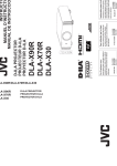
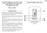
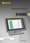
V0.3 Rev.0 Date:8/3/2012 Hardware:rev1.2 Firmware: V0.3 DISPLAY TFT 5.7” USER MANUAL AND PROGRAMMING OS: Windows Xp 1 CONTENTS: Technical Data ..................................................................................................................................... 3 Connection Scheme.............................................................................................................................. 4 Assembly Kit........................................................................................................................................ 8 Assembly Guide ................................................................................................................................... 8 Configuration Software: TFT display editor ........................................................................................ 9 Back Light .................................................................................................................................. 11 Gong ........................................................................................................................................... 12 Screen saver mode (index 05-06)............................................................................................. 12 Floor ........................................................................................................................................... 13 DATE-WEEKDAY-TIME ........................................................................................................ 13 Lift state ..................................................................................................................................... 14 Logo CE ..................................................................................................................................... 15 Customer Logo ........................................................................................................................... 15 Serial number ............................................................................................................................. 16 Capacity ..................................................................................................................................... 16 Temperature ............................................................................................................................... 16 2. Immagini di sfondo Tab ............................................................................................................. 17 3. Floor table e immagini Tab ........................................................................................................ 18 4. Esporta sulla SD-card Tab ......................................................................................................... 19 DISPLAY TFT 5.7” MENU ............................................................................................................ 4 ERROR LIST ................................................................................................................................. 20 2 Manuale display TFT 5.7” programmable Rev. n. 0 hardware ver1. 2 frw 0.3 software v2.0.1.2 Date: 08/03/2012 For a correct use of the card, please follow this procedure : 1. Check that the packaging is intact. If it isn’t, ask for the warranty to be activated according to the following warranty conditions. 2. When opening the packaging, avoid sharp objects, such as scissors or cutters because they can damage the card. 3. Handle the card only with a ground strip- the electrostatic charges can damage the card and compromise its life. Technical Data 5.7” 320xRGBx240 QWGA 115.2x86.4 [mm] 64K 0.36x0.36 [mm] 59 (-454) 12÷24 VDC ±10% Normally close or normally open 5W Min 0,4 max 1.2m/s Common cathode (common negative) From -20°C to +70°C From -30°C to +80°C DEMO-Magnetics sensors-Optical sensor Overload, out of service, alarm, acknowledged alarm signal, emergency, gong. From 512 MB up to 2GB, format FAT-32 .bmp or .jpeg Screen Resolution Viewing area (WxH) Color Pixel (WxH) Number of floor Power Supply Type of sensors Max. power supply Speed of plant Input activation Temperature working range Storage temperature range Working mode Specific inputs SD-CARD Image format REAR SD CARD FRONT CAA AA CAR AR FS OVL DISC SAL Segnalling SD CARD SOCKET SLOT BATTERY UP DW BUZZER ENTER V1 V2 ESC JP7 JP11 JP14 A B EMEM+ 12 / 24 Vdc Emergency light Power supply 12/ 24 Vdc B Rev .1.2 A MAGNETICS SENSORS/ OPTICAL SENSOR 3 DISPLAY TFT 5.7” MENU Turning on the TFT 5.7” display, the firmware version appears bottom right on the display. The management of the menu on the display is supported starting from firmware version 0.2 To enter the menu press the “ENTER” pushbutton. Down / Decrease Value UP / Increase Value Enter the Menu / Confirm Data Esc 1 10 2 11 Page 1 of 2 09 apr 2010 Time and day 09 29 ven 5 B.light normal 60% 6 B.light standby 120 s 00% 7 Volume 3 3 Date 4 8 Gong 0 9 Working mode MAGNO Read SD card NO Load Software NO 12 Low floor Page 2 of 2 32 Phasing floor 0 Language ENG 1.Date : allows to change the date (day/month /year); 2.Time and day: allows to change the time and the day of week; 3.B.light normal: allows to change the brightness of the display's backlight (00%= Backlight off , 100%= maximum brightness). 4.B.light standby: allows to set the time out to enter the standby mode and the brightness of the backlight in standby mode (00% = display off); 5.Volume: allows to change the buzzer's volume (0 = buzzer disabled); 6.Gong: allows to choose the type of gong; 7.Working mode: allows to choose the operating mode of the display (see working mode, index 02). NOTE: the field “8” and “9” work only with SD-CARD (min 512MB up to 2GB)inserted into the slot. Value Note MAGNO Magnetics sensors Normal open MAGNF Magnetics sensors Normal close OPTOO Optic sensor Normal open OPTOF Optic sensor Normal close CAN/SER Not used DEMO Simulation mode 8.ReadSD card: setting “SI” the display load the project that was previously exported in the SD-card. 9.CLoad Software: setting “SI” will start the firmware update of the TFT Display. Before starting with the firmware upgrade you must be sure that in the SD-card there is the file “DsplTft.hex”. 10.low floor: Allows to set a low floor, 180mm<X<400mm (set the first floor of the couple) 11. Phasing floor. Allows to choose the phasing floor (0 default) 12.Language.It’s possible set the menu language. 4 MAGNETICS SENSORS Working mode: MAGNO-MAGNC Piano N°+1 2D Min= 80mm CONTROL PANEL Impulsore superiore Upper sensor Impulseur supèrieur Impulsore inferiore Lower sensor Impulseur infèrieur 2D Min= 80mm D Min=40mm Floor n° SAL CAA AA CAR AR FS OVL DISC Not used Staffa fissata sul tetto cabina Bracket fixed to cabin in roof Etrier fixè sur le toit de la cabine V1 V2 TFT 200 JP7 JP11 JP14 2D Min= 80mm A B EMEM+ . 2D Min= 80mm 12/24 Vdc + 12 / 24 Vdc 2D Min= 80mm Main floor level Magnet 2D Min= 80mm 2D Min= 80mm PIN SAL DISC OVL FS AR CAR AA CAA DESCRIPTION Not used GONG Overload Out of service Alarm signal received (+) Alarm signal received (-) Alarm (+) Alarm (-) PIN V1 V2 JP7 EM+ JP7 EMJP11 JP14 DESCRIPTION Power supply (+) Power supply (-) Emergency light (+) Emergency light (-) Sensor B (inferior) Sensor A(superior) 5 CONFIGURATION OF A FLOOR VERY SHORT [180mm<X<400mm] LOW FLOOR BETWEEN 1 AND 2 NORMAL CONFIGURATION Floor n° n° Min=320 mm 1 D Max= 30mm 2D Min= 60mm Floor 2 400 ≤ X ≥ 180 mm 2D Min= 60mm 2 Menu Low floor=1 Floor 1 2D Min= 60mm Min=400mm 2D Min= 60mm 0 Phasing floor (0) 2D Min= 60mm MAGNET Aimant Aimant 2D Min= 60mm 6 OPTICAL SENSOR Working mode: OPTOO-OPTOF OPTICAL SENSOR CONFIGURATION NORMAL CLOSE NORMAL OPEN NC Set working mode”OPTOF” NO Set working mode”OPTOO” Modo “Normal”: DIP SWITCHES: (1 ON;2,3,4, OFF) Modo “ISO”: DIP SWITCHES: (3 ON;1,2,4, OFF) 1 2 3 4 1 on 2 3 4 on 3 Control panel 2 SAL CAA AA CAR AR FS OVL V1 V2 SD CARD SOCKET DISC Not used 1 TFT 200 JP7 JP11 JP14 A B EMEM+ . 20mm 12/24 Vdc 0 + 12 / 24 Vdc optical sensor A B GND +24 + 24 Vdc -1 PIN SAL DISC OVL FS AR CAR AA CAA DESCRIPTION Not used GONG Overload Out of service Alarm signal received (+) Alarm signal received (-) Alarm (+) Alarm (-) PIN V1 V2 JP7 EM+ JP7 EMJP11 JP14 DESCRIPTION Power supply (+) Power supply (-) Emergency light (+) Emergency light (-) Sensor B (inferior) Sensor A(superior) 7 SIGNALLING: Alarm active (AA-CAA) Alarm received (AR-CAR) Out of order (FS) Overload (OVL) Emergency light (JP7) Assembly Kit CODE: KIT-FIS-TFT5.7” - Plexiglass glass -4 spacers -4 hexagonal self-blocking nuts Assembly Guide ● Insert the glass ● Insert the four spacers in the screws ● Insert the TFT display. Please, be careful to the assembly direction (see image 1) ● Fix the display with the self-blocking nuts CONNECTOR ENCUMBRANCE CUT OUT CONNECTOR ENCUMBRANCE 8 Configuration Software: TFT display editor Recommended operating system: Windows XP The software is tab-structured for an easy and quick navigation. The software has 4 tabs: 1. Layout and working mode, 2. BackGround Images, 3. Floor Table and Images, 4. Export on the SD-CARD. In the menu bar[1] are available the following buttons: New Project: allows to create a new project with the “default” settings. Open Project: allows to open a project which has already been saved (.ssd file); Save Project: allows to save the project (.ssd file); Zoom: allow to enlarge or shrink the view of the print layout; Orientation: 0° (horizzontal) 90° (vertical) NOT USED. 9 1. Layout and Working Mode This is the main tab where it is possible to: view the screen layout of the display, the type of GONG amd the volume; rearrange the position of the fields of the screen: lift state, serial number, floor, CE logo, capacity, weekday time and date;choose the logo (Customer logo); choose the lift state icons (Out of Service, Overload, Alarm Active, Alarm Received, emergency); choose the arrows icons (up and down icons); choose the font and color of the floor number, day of the week, date and time, lift serial number, capacity; CUSTOMER LOGO TIME/DATA/Week day Serial number. N° Floor LIFT STATE CAPACITY CE LOGO Arrow direction It is possible to change the position of each icon of the display holding the left mouse button on an icon and moving the mouse. This is not possible for the “capacity” flield that is fixed and can not be moved. 10 PROGRAMMING Item Index Back light 00~01 gong 03~04 Screen saver- NOT USED! 05~26 NOT USED! Lift Up/Down arrow 27~35 Floor 36~42 Date-weekday-Time 43~84 Lift state 85~107 CE logo 108~113 Customer logo 114~119 Serial number 120~127 Capacity 128~135 Temperature NOT USED! 136~143 NOT USED! Back Light (index 00-01) It is possible to program the auto-off time of the back light (index 00). To disable this feature set the value '0' to adress '00' (the display will stay always lit). Index Item Value Note 00 Auto turn off lcd back light second 120 01 Display light level 60 Auto turn off time of the display back light (in seconds). 0 = feature disabled Light intensity of the display. 11 Gong (index 03-04) Index Item Value Note 03 Gong type Gong 0 Type of gong [0,1,2] 04 Gong volume 3 Volume of the display gong [0=disattivo, 5=vol. max] Screen saver mode (index 05-06) NOT USED! Colore fixed background and capacity (index 12) Value Index Item 12 Fixed background color 0x0000 (black) Note Change the background colour of the fields “Fixed background” and “capacity”. Default Background image (index 18-26) NOT USED! Lift Up/Down arrows (index 28~35) Index Item Value Note 28 Lift Up Down arrow left 0 X Position 29 Lift Up Down arrow top 0 Y Position 30 Lift Up Down arrow width 80 (pixel) Width 31 32 Lift Up Down arrow height Lift Up arrow image.0 68 (pixel) File path Height File path for the up arrow image 0 33 Lift Up arrow image.1 File path File path for the up arrow image 1 34 Lift Down arrow image.0 File path File path for the down arrow image 0 35 Lift Down arrow image.1 File path File path for the down arrow image 1 The indexes 28 and 29 allow to modify the position of the images of the arrows within the field “fixed used backgroud” (black background). The indexes 30 and 31 allow to modify the sizes of the images of the arrows. For each arrow (up and down arrow) can be used two images (index 32-33 e 34-35) which alternate during the normal operation. For example, in up direction, you will see the image loaded at index 32 alternating with the image loaded at index 33. 12 Floor (index 36~42) Index Item Value Note 36 Floor text font Font type Font Type - size 37 Floor text font color Colour 38 39 Floor text left Floor text top 0XF5F5F5 (Bianco) 0 100 40 Floor text width 80 Width 41 Floor text height 60 Height 42 Floor text preview text 36 Number of floor showed in the preview X Position Y Position NOTE: the software works with .bmp and .jpg images. DATE-WEEKDAY-TIME (index 43~84) Index Item Value Note 42 Floor text preview text 36 Number of floor preview 43 Date text used true True = on | false = off 44 Date text style 27-gen-2010 Date format: ● gg/mm/aaaa ● aaaa/mm/gg ● mm/gg 45 46 Date text font Date text font color Font name..size... Date's Font type-style-size Date's Font Colour 47 48 49 50 51 Date text left Date text top Date text width Date text height Date text January 52 Date text February Feb 53 Date text March Mar 54 Date text April Apr 55 Date text May Mag 56 Date text June Giu 57 Date text July Lug 58 Date text August Ago 59 Date text September Set 60 Date text October Ott 0FAEBD7 (Bianco) 0 127 80 16 Gen X Position Y Position Width Height Allow to change the 3 characters indicating the month (Max 3 characters for each month) 13 61 Date text November Nov 62 Date text Dicember Dic 63 Weekday text used True True = weekday visualization enabled False = weekday visualization disabled 64 65 Weekday text font Weekday text font color Font name..size.. 66 67 68 69 Weekday text left left Weekday text top Weekday text width Weekday text height 0FAEBD7 (Bianco) 0 165 80 16 Weekday Font type-style-size Weekday Font Colour 70 Weekday text monday Lunedì 71 Weekday text tuesday Martedì 72 Weekday text wednsday Mercoledì 73 Weekday text thursday Giovedì 74 Weekday text friday Venerdì 75 Weekday text saturday Sabato 76 Weekday text sunday Domenica 77 Time text used True 78 Time text font Font name..size.. 79 Time text font color Time's Font Colour 80 Time text left 0FAEBD7 (Bianco) 20 81 Time text top 148 Y position 82 Time text width 40 Width 83 Time text height 16 Height 84 Time text preview 00:00 At the startup, the software loads the current time of the PC. X Position Y Position Width Height The text indicating the day, can be changed with a new one. For example, writing 'MON' at index 58 makes the display show the string 'MON' every monday. True = Time enabled False= Time disabled Time's Font type – style - size X Position Lift state (index 85~107) Index 85 86 87 88 89 90 91 92 93 94 95 96 Item Lift state used Lift state left Lift state top Lift state width Lift state height Lift state maintain image 0 Lift state maintain image 1 Lift state full load image 0 Lift state full load image 1 Lift state out of order image.0 Lift state out of order image.1 Lift state overload image.0 Value true 116 196 176 34 NOT USED! NOT USED! NOT USED! NOT USED! File path File path File path Note True=on | false=off X Position Y Position Width Height NOT USED! NOT USED! NOT USED! NOT USED! Out of Order icon 0 Out of Order icon 1 Overload icon 0 14 97 98 99 100 101 102 103 104 105 106 107 Lift state overload image.1 Lift state fire image.0 Lift state fire image.1 Lift state alarm active image.0 Lift state alarm active image.1 Lift state alarm received image.0 Lift state alarm received image.1 Lift state power failure image.0 Lift state power failure image.1 Lift state VIP failure image.0 Lift state VIP failure image.1 File path NOT USED! NOT USED! File path File path File path File path File path File path NOT USED! NOT USED! Overload icon 1 NOT USED! NOT USED! Alarm Active icon 0 Alarm Active icon 1 Alarm Received icon 0 Alarm Received icon 1 Power Failure icon 0 Power Failure icon 1 NOT USED! NOT USED! NOTE: the software works with .bmp and .jpg images. Logo CE (index 108~113) Index Item Value Note 108 CE logo used True True=on | false=off 109 CE logo left 0 X Position 110 CE logo top 208 Y Position 111 112 CE logo width CE logo height 32 32 Width Height 113 CE logo image File path Path of CE mark image Customer Logo (index 114~119) Index Item Value Note 114 Customer logo used True True=on | false=off 115 Customer logo left 116 X Position 116 Customer logo top 0 Y Position 117 118 Customer logo width Customer logo height 176 40 Width Height 119 Customer logo image File path Path of logo image 15 Serial number (index 120~127) Index Item Value Note 120 Serial number used 121 Serial number font 122 Serial number font color 0FAEBD7(Bianco) Serial Number Font Colour 123 124 Serial number left Serial number top 0 188 X Position Y Position 125 Serial number width 80 Width 126 Serial number height 16 Height 127 Serial number text True Font name..size. Nr.0123456 True=on | false=off Font type – style - size System Serial Number Capacity (index 128~135) Index Item Value Note 128 Capacity used 129 Capacity font Font name..size. Capacity Font type – style - size 130 Capacity font color 0FAEBD7(Bianco) Capacity Font Colour 135 Capacity text 640 KG 6 PERS. Capacity of the system True True=on | false=off Temperature (index 136~142) NOT USED! 16 2. User backgrounf images In Tab 2, “immagini di sfondo” you can select and load the images which will be visualized at each floor. Pay attention please to the file type of the images that you want to use: the display works with .bmp and .jpg images. To improve the quality of the image visualization, we suggest the use of square images (for example 700x700 pixel). Double-clicking with the left mouse button on the field 'value' of the table, opens a window that allows to select the image to load. Select the format of the image (.bmp or .jpg), select the desired image and click the 'Apri' button. NOTA: the TFT 5.7” display supports up to 35 images. 17 3. Floor table and images Tab 3 “floor table e immagini” allows to associate the background images (loaded in tab 2) to several floors. Double-Clicking with the left mouse button under the column “index of background image” [2] fig.10, will open a drop-down window where you can choose the desired background for that floor, among those previously loaded (ref. ch. 2). In the first row of the table, there is a field [1] fig.10 where it is possible to set the number that the display have to show for the fist floor of the system, the other floor will be automatically recalculated. For example, if you want the display shows '-1' for the first floor of the system, then select the value '-1' in the field [1] shown. Associate a character to a foor Suppose we want to see the characters “GA” to floor '-1'. Just Double click with the left mouse button on the column “Floor text (2 bytes)” in the row corresponding to the desired floor, in our case '-1', and write the desired characters (max 2 characters). 18 4. Make and copy to SD-card The TFT 5.7” supports SD-CARD min 512MB up to 2 GB of memory. NOTE: Format the SD-CARD with FAT 32 file system. NOTE: The TFT Display work only with “exported” project. Once the project is finished and you want to load it on the SD-CARD for the TFT, you have to “export” it and not “save” it. In Tab “4.Esporta sulla SD-Card”, you can export your project directly to the SD-Card or choose a different path. To start the export procedure of the project on SD-CARD: -Select the path of the SD-CARD; -Click on the button “Export” . With the “Import” button you can load a project that was previously exported on the SD-CARD. 19 ERROR LIST Error 1 2 PROBABLE CAUSE The file Config.ini is not present in the SD-card The lenght of the Config.ini file is not correct Default Background... Error PROBABLE CAUSE Capacity Maxim load of the system... 50 ...missing parameters 51 ...errors in the coordinates 52 ...image not available 53 ...error in the image file CE Logo... 4 ...missing parameters 5 …wrong activation time 6 …wrong time period 55 ...missing parameters ...errors in the coordinates …errors in the coordinates 56 8 …image not available 57 ...image not available 9 …error in the image file Fixed background (black)… 58 ...error in the image file Customer Logo... 10 ...missing parameters 60 ...missing parameters 11 …errors in the coordinates Floor's background... 61 ...errors in the coordinates 62 ...image not available 14 ...missing parameters 63 15 …'used' field set to False ...error in the image file Serial Number... 16 …errors in the coordinates 65 ...missing parameters 17 …image not available Floor's number… 66 ...errors in the coordinates 67 ...image not available 20 ...missing parameters 68 21 ...errors in the coordinates ...error in the image file DATA... 22 …images not available 70 ...missing parameters …filename too long 71 ...errors in the coordinates …not enough images Images Table - Floor… 72 ...style not available 73 ...style is not valid 26 ...missing parameters 74 ...images not available 27 …error in the 'first floor' field 75 ...error in the numbers 28 …incomplete table Up / Down Arrows… 76 ...error in the separators 77 ...error in the month Time... 7 23 24 30 ...missing parameters 31 …coordinate errors 80 ...missing parameters …Up arrow image error 81 ...errors in the coordinates …Down arrow image error Alarm and status… 82 ...images not available 83 ...error in the numbers 35 ...missing parameters 84 36 …errors in the coordinates ...error in the separators Day of the Week... 37 …error in the Overload image file 86 …missing parameters 38 …error in the Full Load image file 87 …errors in the coordinates 39 …error in the Out of Service image file 88 …images not available 40 …error in the Alarm Active image file …error in the Alarm Received image file 89 …error in the image file Temperature... 90 …missing parameters 91 …errors in the coordinates 92 …images not available 93 …error in the numbers 94 …error in the separators 32 33 41 42 …error in the Emergency image file 43 …error in the Fire image file 44 …error in the Maintenece image file 45 …error in theVIP image file 20 History of version: VERSION FIRMWARE:V0.3 SLOT BATTERY 3V SD CARD UP UP TFT200 TFT200 DW DW ENTER ENTER ESC V1 V2 V1 V2 ESC NOTE: If a power failure occurs, the calendar (Date and Time) will be reset. JP7 JP11 JP14 Rev.1.2 A A B EMEM+ Rev.1.2 B EMEM+ JP7 JP11 JP14 SD CARD VERSION FIRMWARE:V0.2 Calendar ok! 21 22 23 Vega Srl Via degli appennini 11 C/da Capparuccia - 63020 Ponzano di Fermo (AP) – Italy P.Iva 01578140442 Tel. +39 0734. 631941 Interno 1 Fax +39 0734. 636098 www.vegalift.it 24