1
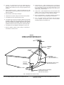
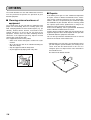
Model TT-15S1 User Guide
Turntable
CAUTION
RISK OF ELECTRIC SHOCK
DO NOT OPEN
CAUTION: TO REDUCE THE RISK OF ELECTRIC SHOCK,
DO NOT REMOVE COVER (OR BACK)
NO USER-SERVICEABLE PARTS INSIDE
REFER SERVICING TO QUALIFIED SERVICE PERSONNEL
The lightning flash with arrowhead symbol within an
equilateral triangle is intended to alert the user to the
presence of uninsulated “dangerous voltage” within the
product’s enclosure that may be of sufficient magnitude
to constitute a risk of electric shock to persons.
The exclamation point within an equilateral triangle is
intended to alert the user to the presence of important
operating and maintenance (servicing) instructions in
the literature accompanying the product.
WARNING
TO REDUCE THE RISK OF FIRE OR ELECTRIC SHOCK,
DO NOT EXPOSE THIS PRODUCT TO RAIN OR MOISTURE.
CAUTION: TO PREVENT ELECTRIC SHOCK, MATCH WIDE
BLADE OF PLUG TO WIDE SLOT, FULLY INSERT.
ATTENTION: POUR ÉVITER LES CHOC ÉLECTRIQUES,
INTRODUIRE LA LAME LA PLUS LARGE DE LA FICHE DANS
LA BORNE CORRESPONDANTE DE LA PRISE ET POUSSER
JUSQU’AU FOND.
NOTE:
This equipment has been tested and found to comply with the
limits for a Class B digital device, pursuant to Part 15 of the FCC
Rules. These limits are designed to provide reasonable
protection against harmful interference in a residential
installation. This equipment generates, uses and can radiate
radio frequency energy and, if not installed and used in
accordance with the instructions, may cause harmful interference
to radio communications. However, there is no guarantee that
interference will not occur in a particular installation. If this
equipment does cause harmful interference to radio or television
reception, which can be determined by tuning the equipment off
and on, the user is encouraged to try to correct the interference
by one or more of the following measures:
- Reorient or relocate the receiving antenna.
- Increase the separation between the equipment and receiver.
- Connect the equipment into an outlet on a circuit different
from that to which the receiver is connected.
- Consult the dealer or an experienced radio/TV technician
for help.
NOTE:
Changes or modifications not expressly approved by the party
responsible for compliance could void the user’s authority to
operate the equipment.
NOTE TO CATV SYSTEM INSTALLER:
This reminder is provided to call the CATV (Cable-TV) system installer’s attention to Section 820-40 of the NEC which provides guidelines
for proper grounding and, in particular, specifies that the cable ground shall be connected to the grounding system of the building, as close
to the point of cable entry as practical.
IMPORTANT SAFETY
INSTRUCTIONS
READ BEFORE OPERATING EQUIPMENT
This product was designed and manufactured to meet strict quality and
safety standards. There are, however, some installation and operation
precautions which you should be particularly aware of.
1. Read Instructions – All the safety and operating instructions
should be read before the product is operated.
2. Retain Instructions – The safety and operating instructions
should be retained for future reference.
12. Grounding or Polarization – This product may be equipped with a
polarized alternating-current line plug (a plug having one blade
wider than the other). This plug will fit into the power outlet only
one way. This is a safety feature. If you are unable to insert the
plug fully into the outlet, try reversing the plug. If the plug should
still fail to fit, contact your electrician to replace your obsolete
outlet. Do not defeat the safety purpose of the polarized plug.
3. Heed Warnings – All warnings on the product and in the
operating instructions should be adhered to.
4. Follow Instructions – All operating and use instructions should be
followed.
5. Cleaning – Unplug this product from the wall outlet before
cleaning. Do not use liquid cleaners or aerosol cleaners. Use a
damp cloth for cleaning.
6. Attachments – Do not use attachments not recommended by the
product manufacturer as they may cause hazards.
7. Water and Moisture – Do not use this product near water-for
example, near a bath tub, wash bowl, kitchen sink, or laundry
tub, in a wet basement, or near a swimming pool, and the like.
8. Accessories – Do not place this product on an unstable cart,
stand, tripod, bracket, or table. The product may fall, causing
serious injury to a child or adult, and serious damage to the
product. Use only with a cart, stand, tripod, bracket, or table
recommended by the manufacturer, or sold with the product. Any
mounting of the product should follow the manufacturer’s
instructions, and should use a mounting accessory
recommended by the manufacturer.
9. A product and cart combination should be moved with care.
Quick stops, excessive force, and uneven surfaces may cause
the product and cart combination to overturn.
AC POLARIZED PLUG
13. Mains Cord Protection – Mains cord should be routed so that
they are not likely to be walked on or pinched by items placed
upon or against them, paying particular attention to cords at
plugs, convenience receptacles, and the point where they exit
from the product.
14. Protective Attachment Plug – The product is equipped with an
attachment plug having overload protection. This is a safety
feature. See Instruction Manual for replacement or resetting of
protective device. If replacement of the plug is required, be sure
the service technician has used a replacement plug specified by
the manufacturer that has the same overload protection as the
original plug.
15. Outdoor Antenna Grounding – If an outside antenna or cable
system is connected to the product, be sure the antenna or cable
system is grounded so as to provide some protection against
voltage surges and built-up static charges. Article 810 of the
National Electrical Code, ANSI/NFPA 70, provides information
with regard to proper grounding of the mast and supporting
structure, grounding of the lead-in wire to an antenna discharge
unit, size of grounding conductors, location of antenna-discharge
unit, connection to grounding electrodes, and requirements for
the grounding electrode. See Figure 1.
16. Lightning – For added protection for this product during a
lightning storm, or when it is left unattended and unused for long
periods of time, unplug it from the wall outlet and disconnect the
antenna or cable system. This will prevent damage to the
product due to lightning and power-line surges.
10. Ventilation – Slots and openings in the cabinet are provided for
ventilation and to ensure reliable operation of the product and to
protect it from overheating, and these openings must not be
blocked or covered. The openings should never be blocked by
placing the product on a bed, sofa, rug, or other similar surface.
This product should not be placed in a built-in installation such as
a bookcase or rack unless proper ventilation is provided or the
manufacturer’s instructions have been adhered to.
11. Power Sources – This product should be operated only from the
type of power source indicated on the marking label. If you are
not sure of the type of power supply to your home, consult your
product dealer or local power company. For products intended
to operate from battery power, or other sources, refer to the
operating instructions.
17. Power Lines – An outside antenna system should not be located
in the vicinity of overhead power lines or other electric light or
power circuits, or where it can fall into such power lines or
circuits. When installing an outside antenna system, extreme
care should be taken to keep from touching such power lines or
circuits as contact with them might be fatal.
18. Overloading – Do not overload wall outlets, extension cords, or
integral convenience receptacles as this can result in a risk of fire
or electric shock.
19. Object and Liquid Entry – Never push objects of any kind into
this product through openings as they may touch dangerous
voltage points or short-out parts that could result in a fire or
electric shock. Never spill liquid of any kind on the product.
20. Servicing – Do not attempt to service this product yourself as
opening or removing covers may expose you to dangerous
voltage or other hazards. Refer all servicing to qualified service
personnel.
21. Damage Requiring Service – Unplug this product from the wall
outlet and refer servicing to qualified service personnel under the
following conditions:
22. Replacement Parts – When replacement parts are required, be
sure the service technician has used replacement parts specified
by the manufacturer or have the same characteristics as the
original part. Unauthorized substitutions may result in fire,
electric shock, or other hazards.
23. Safety Check – Upon completion of any service or repairs to this
product, ask the service technician to perform safety checks to
determine that the product is in proper operating condition.
a. When the Mains cord or plug is damaged.
b. If liquid has been spilled, or objects have fallen into the product.
c. If the product has been exposed to rain or water.
d. If the product does not operate normally by following the operating
instructions. Adjust only those controls that are covered by the
operating instructions as an improper adjustment of other controls
may result in damage and will often require extensive work by a
qualified technician to restore the product to its normal operation.
24. Wall or Ceiling Mounting – The product should be mounted to a
wall or ceiling only as recommended by the manufacturer.
25. Heat – The product should be situated away from heat sources
such as radiators, heat registers, stoves, or other products
(including amplifiers) that produce heat.
e. If the product has been dropped or damaged in any way, and
f. When the product exhibits a distinct change in performance –
this indicates a need for service.
FIGURE 1
EXAMPLE OF ANTENNA GROUNDING AS PER
NATIONAL ELECTRICAL CODE, ANSI/NFPA 70
ANTENNA
LEAD IN
WIRE
GROUND
CLAMP
ANTENNA
DISCHARGE UNIT
(NEC SECTION 810-20)
ELECTRIC
SERVICE
EQUIPMENT
GROUNDING CONDUCTORS
(NEC SECTION 810-21)
GROUND CLAMPS
POWER SERVICE GROUNDING
ELECTRODE SYSTEM
(NEC ART 250, PART H)
NEC - NATIONAL ELECTRICAL CODE
This Class B digital apparatus complies with Canadian ICES-003.
Cet appareil numérique de la Classe B est conforme à la norme
NMB-003 du Canada.
CONTENTS
CONTENTS ............................................................................................................................................1
BEFORE USE .........................................................................................................................................2
ACCESSORIES ......................................................................................................................................3
ASSEMBLING AND ADJUSTING...........................................................................................................5
NAMES AND FUNCTIONS...................................................................................................................10
CONNECTIONS AND OPERATION.....................................................................................................11
TROUBLE SHOOTING .........................................................................................................................12
SPECIFICATIONS AND EXTERNAL DIMENSIONS DIAGRAM ..........................................................13
OTHERS ...............................................................................................................................................14
1
BEFORE USE
This section must be read before any connection is made to
the mains supply.
7 Equipment Main Power Setting
7 Caution: Do not lose the bearing.
(View from underneath the turntable chassis)
Your Marantz product has been prepared to comply with the
household power and safety requirements that exist in your
area.
TT-15S1 can be powered by 120V AC only.
7 Copyright
Recording and playback of any material may require
consent. For further information refer to the following:
- Copyright Act 1956
- Dramatic and Musical Performers Act 1958
- Performers Protection Acts 1963 and 1972
- Any subsequent statutory enactments and orders
7 Do Not Locate in the Following
Places
To ensure long-lasting use, do not locate the TT-15S1 where:
• Exposed to direct sunlight.
• Near to sources of heat such as heaters.
• Highly humid or poorly ventilated.
• Dusty.
• Subjected to mechanical vibrations.
• On wobbly, inclined or otherwise unstable surfaces
• Radiated heat is blocked such as in cramped audio racks.
To ensure proper heat radiation, ensure the below
clearance from walls and other equipment.
Front
Turntable chassis
Center shaft hole
Bearing
Center shaft
There is a bearing located inside the center shaft hole in the
turntable chassis. When the turntable leaves the factory, the
center shaft hole is covered with tape to prevent the bearing
from falling out. Sometimes after removing the tape, the
bearing falls out when the turntable is turned over. If the
center shaft is inserted when there is no bearing in the
center shaft hole, the turntable will not rotate. Therefore,
make sure that the bearing does not fall out of the center
shaft hole when assembling the turntable.
Furthermore, if the turntable is disassembled for
transportation etc. cover the center shaft hole with tape etc.
to prevent the bearing from falling out.
7 Before using
• Thoroughly remove dust or dirt from the
stylus point and record.
0.2m
0.2m
0.2m
If you play records when there is dirt/dust on the stylus,
not only will the stylus have poor contact with the record
causing poor sound quality, it will also increase the rate
of wear of both the stylus and record. Gently remove
dirt/dust by brushing with a soft tipped brush from the
base of the stylus to the tip. Also wipe the record with a
good quality record cleaner.
Side
• Install the turntable chassis and turntable
so that they are level.
0.2m
0.2m
0.2m
It is possible to adjust the height of the legs by rotating
them. However, as there are only 3 legs, the height may
not be adjustable in some cases.
In such cases, adjust the rack itself so that it is horizontal.
• About howling and hum
Howling occurs when sound from the speaker or vibration is
transmitted to the player and is picked up by the cartridge
again. If howling occurs when the volume is increased,
check the positions of the speakers and turntable, and
move them to locations where neither vibration nor sound is
transmitted to the turntable. Hum noise occurs because of
electromagnetic waves that are generated from other
electronic devices. Check the position of other electronic
devices that are near to the turntable, especially the
amplifier. Also, hum or noise occurs if the ground is not
connected correctly. Check that the ground wire is securely
connected to the GND terminal on the amp/mixer.
2
ACCESSORIES
Before using the turntable, please make sure that you have all of the following accessories.
1. Turntable chassis
5. Motor
2. Center shaft
6. Motor pulley (for 60Hz areas)
3. Tone arm
7. Gloves (pair)
4. Turntable
8. Ground wire
3
ACCESSORIES
9. 2 Drive belts (1 spare belt)
13. Record clamp (“Clever clamp” produced by
Southern Engineering)
10. Bearing oil
14. Counter weight
11. Turntable sheet
15. Tone arm height adjustment sheet
12. 3 Allen wrenches (large/medium/small)
1 adjustment screwdriver
4
16. Cartridge (MM type) by Clearaudio
ASSEMBLING AND ADJUSTING
1. Installing the ground wire
4. Attaching the tone arm
Connect the ground wire to the turntable shaft base.
a)
Pass the Phono cable that is connected to the tone arm
through the tone arm attachment hole.
Turntable shaft base
Tone arm
phono cable
Ground wire
Turntable chassis
b)
2. Inserting the center shaft
Insert the center shaft into the turntable chassis.
Determine the height and direction of the tone arm
attachment position.
b-1) Height
Bear in mind that the height position of the tone arm is
different depending on whether or not the turntable
sheet is used.
Center shaft
Turntable chassis
•
When using the turntable sheet
The correct height position is achieved when the
counter weight and tone arm height adjustment sheet
are placed beneath the arm lifter.
With turntable sheet
Arm lifter
3. Installing the turntable
Place the turntable onto the center shaft.
Turntable
Counter weight
Tone arm height
adjustment sheet
Center shaft
•
When not using the turntable sheet
The correct height position is achieved when just the
counter weight is placed beneath the arm lifter.
(Tone arm height adjustment sheet is not used.)
No turntable sheet
Arm lifter
Counter weight
5
ASSEMBLING AND ADJUSTING
5. Attaching the cartridge
b-2) Direction
The direction position is correct when the tone arm is
parallel with the side of the turntable base.
a)
Use the Allen wrench (medium) to remove the head
shell from the tone arm.
Allen wrench (medium)
Tone arm
Tone arm
Head shell
Based side
of turntable
Parallel
b)
Attach the cartridge to the head shell.
b-3) When you have determined the height and direction of
the tone arm attachment position, tighten the tone arm
fixing screw using the Allen wrench (large).
Screw
Head shell
Cartridge
Allen wrench (large)
Remove
After fixing the tone arm in place, remove the counter
weight and tone arm height adjustment sheet.
6
• When attaching the cartridge that was included with the
turntable, use the aluminum screw and slotted
screwdriver that are also included.
• When attaching a different cartridge, choose a cartridge
that is compatible with the cartridge weight range for the
tone arm.
Compatible cartridge weight: 3-18g
ASSEMBLING AND ADJUSTING
c)
Attach the cartridge that you attached in the previous
step to the tone arm.
6. Adjusting arm balance
a)
Remove the anti-skating adjustment screw.
Screw
Tone arm
Head shell
Cartridge
Anti-skating
adjustment screw
•
When using the included cartridge
Attach to the front attachment hole position on the tone
arm.
b)
Attach the counter weight to the back of the arm.
Counter weight
Tone arm
•
When using a different cartridge
Attach the cartridge so that it is 32mm from the stylus
tip.
c)
Remove the cartridge cover.
32mm
d)
Connect the 4 tone arm wires to their respective
terminals on the attached cartridge.
For the included cartridge
White
Blue
Cartridge cover
Red
Green
Caution:
When using a different cartridge, refer to the cartridge
instruction manual to connect the wires.
Make sure that the cartridge stylus tip does not touch the
turntable etc. and that the stylus tip does not get
damaged.
Caution:
Be careful when connecting the wires, as they are thin
and break easily.
It is easy to connect the wires if you use tweezers etc.
7
ASSEMBLING AND ADJUSTING
Tone arm
Rotating the counter weight by 1 scale graduation adds
0.1g of pressure. Therefore, as the counter weight has
5 graduations, one complete turn will add 0.5g of
pressure.
Counter
weight
0
0.
4
0 .1
As the recommended stylus pressure for the included
cartridge is 2.2g, rotate the counter weight 4 complete
turns and 2 scale graduations from the reference point
at balance adjustment to reach the correct stylus
pressure position.
Lifter lever
e)
3
0.
Find the
balance
2
Lower the lifter lever, and rotate the counter weight to
balance the tone arm so that it is parallel with the
turntable.
0.
d)
After finding the balance, raise the lifter lever and attach
the anti-skating adjustment screw.
Counter weight
0.1
0.4
0
Rotate 4 complete turns and
2 graduation points
from the reference point.
Stylus pressure 2.2g
Anti-skating
adjustment screw
When using a different stylus, check the recommended
stylus pressure and adjust to the correct stylus
pressure.
7. Stylus pressure adjustment
Adjust to the recommended stylus pressure of the
cartridge being used.
When the tone arm is balanced, rotate the counter
weight in the direction of the arrow using the counter
weight “0” point display as a reference point.
8. Anti-skating adjustment
Adjust the anti-skating adjustment screw in line with the
stylus pressure of the cartridge being used.
For the included cartridge, adjust so that the screw
position is approximately half way out.
0.1
0.4
Reference point
Counter weight
Screw half way position
Anti-skating
adjustment screws
8
ASSEMBLING AND ADJUSTING
9. Attaching the motor pulley
11. Installing the belt
Attach the motor pulley to the motor.
Use one of the belts included and attach it between the
motor pulley and turntable.
Using the adjustment screwdriver included to fix the
pulley’s 3 plastic screws.
When attaching the belt, hook it over the central slot.
Be careful not to turn the screws with too much force,
as they are made from plastic and can break easily.
(There are 2 belts included with the turntable. Please
keep one as a spare.)
Central slot
Included screwdriver
for adjustment
When attaching the pulley, fix with approximately 3mm
space between the pulley and motor.
3mm
The positions for attaching the motor pulley belt are
different when playing 45 or 33 rpm records.
Change the position of the belt to suit the record that
you want to play.
Attach to the
lower side
33 rpm
Attach to the
upper side
45 rpm
Caution:
10. Installing the motor
From underneath the turntable chassis, place the motor in
the hole section at the back left of the turntable chassis.
When changing the position of the belt, use the gloves
included, and be careful not to damage the belt in any
way.
(Do not fix it to the turntable base)
Does not touch
Caution:
When installing the motor, in order to prevent motor
vibrations from being transmitted to the turntable base,
install the motor so that it does not touch the base.
9
NAMES AND FUNCTIONS
q
!0
w
!1
o
e
i
r
u
t
y
q Power switch (OFF, ON)
When it is switched ON, the turntable rotates.
w Pulley
This is changed to suit the rpm speed of the record to be
played.
33 1/3 rpm record ....................................[Lower side]
45 rpm record ..........................................[Upper side]
e Belt
r Turntable
t Turntable sheet
y Cartridge
u Tone arm
i Lifter lever
This is used to raise and lower the tone arm.
10
o Anti-skating knob
When a record is being played, a certain amount of force
is exerted on the stylus that pulls it towards the center.
This knob is used to perform adjustments that cancel out
that force.
!0 Counter weight
This is used to balance the toner arm and to adjust the
stylus pressure.
!1 Record clamp
This is effective in holding the record when records are
being played without a turntable sheet, or when playing
warped records.
Use it as shown in the diagram.
CONNECTIONS AND OPERATION
Amplifier
Power
switch
White
Red
TT-15S1
7 Connections
6. Lift the lifter lever, then use the head shell finger hook to
Make sure that the power supply to both this turntable and
the amplifier are OFF before you start connecting.
7. Lower the lifter lever.
move the tonearm to the play position of the record.
The tonearm slowly lowers the stylus onto the record,
and the record starts to play.
1. Connect the PHONO cables (L: white, R: red) that are
connected to the toner arm to the corresponding L and
R [PHONO] input terminals on your amplifier.
2. Connect both the ground wire that is connected to the
bottom of the turntable and GND cable that is
connected to the toner arm to the GND terminal (ground
terminal) on your amplifier.
3. Plug the motor power cord into an AC 120V outlet.
Caution
If your amplifier etc. has power outlets on the back panel,
plug the turntable into one of these outlets. In this case,
refer to the instruction manual for amplifier, etc. and
check that the power outlet has enough power capacity.
7 Operation
7
Starting to play records
1. Plug the turntable power cable into an AC outlet.
2. Turn on the amplifier, and select input to [PHONO].
Caution
• Do not allow the turntable to be jolted or vibrated while
playing a record.
• Always stop the turntable when changing records.
• Always turn down the amplifier volume when placing the
stylus on or removing it from the record.
7
When the record has finished
1. Gently raise the lifter lever.
The tone arm raises, and the stylus separates from the
record.
2. Return the tone arm to the arm rest using the head shell
finger hook.
3. Lock the tone arm in the arm rest.
4. Switch the power button OFF.
The turntable stops rotating.
Also, set the amplifier phono equalizer to either [MM] or
[MC] to suit the attached cartridge. (If you are using the
included cartridge, set to [MM])
3. Set a record on the turntable.
* If you are playing an EP record, use a commercially
available EP adapter.
4. Attach the belt to the motor pulley in the correct position
for the chosen record.
5. Switch the power button ON.
The turntable will begin to rotate at the speed selected
in operation 4 above.
Caution
In order to reduce noise, the motor torque has been set
to the minimum level in this turntable. Therefore, the
turntable sometimes does not rotate when the power is
switched on. If this happens, gently rotate the turntable a
little in the clockwise direction by hand.
11
TROUBLE SHOOTING
If you think a malfunction has occurred, first check the
points listed below.
7 Check Items
7
Are each of the connections correct?
The stylus won’t lower onto the record.
7
Are you operating the turntable correctly
as described in this instruction manual?
• Is the tone arm height adjusted correctly?
If the turntable does not operate correctly, check all of the
items in the following table.
However, if none of the items in the following table
correspond to the problem, it is possible there is a fault with
your turntable. In this case, turn off the power, un-plug the
power cord from the AC outlet, and contact your dealer.
If you do not remember where you bought this turntable,
contact the Marantz Authorized Service Center.
7
About the included cartridge
You cannot replace the stylus in the cartridge that is
included with this turntable.
If you wish to exchange the cartridge itself, contact the
Marantz Authorized Dealer.
• Is the stylus pressure adjusted correctly?
• Is the arm balanced correctly?
There is no sound.
• Are the cartridge and head shell connected correctly?
• Is the output cord connected to the amplifier correctly?
• Are the amplifier knobs adjusted and switched correctly?
A humming noise is emitted.
• Is the output cord ground wire connected to the amplifier?
• Is the output cord plug connected securely?
• Is the head shell fixed securely with the lock nut?
The stylus jumps.
• Is the stylus pressure adjusted to the correct stylus
pressure?
• Is the record warped or scratched?
• Is there a lot of dust collected on the stylus?
The arm stops progressing half way through
the record.
• Is the record scratched?
• Is there something touching the arm?
The sound is too quiet. Or too loud.
• Is the amplifier connection switching suitable for the type
of cartridge being used (MC/MM)?
12
SPECIFICATIONS AND EXTERNAL DIMENSIONS DIAGRAM
440
350
110
350
7 Turntable section
RPM
................................................33 1/3 rpm, 45 rpm
7 Included Cartridge (Clearaudio)
Frequency response...................................20Hz - 20 kHz
Turntable ............................................High density acrylic
3.6 mV
˜
Channel separation ............................................ > 30 dB
Turntable depth ......................................................28 mm
Channel balance..................................................< 0.2 dB
RPM deviation .......................................................±0.2 %
Recommended stylus pressure................................ 2.2 g
S/N ratio...................................................................80 dB
Impedance............................................................0.66 kΩ
Drive system ..........................................Belt drive system
Output voltage (1kHz, 5cm/s)............................
Cantilever ..........................................................Aluminum
7 Tone Arm section
Arm type ........................................2 point radial tone arm
Effective length......................................................239mm
Cartridge weight ....................................................... 6.0 g
7 General Specifications
Overhang ................................................................17mm
Power supply............................................AC120V, 60 Hz
Stylus pressure adjustable range ....0-5g(1 Graduation = 0.1g)
Power consumption .....................................................5W
Compatible cartridge weight ......33-18g (excluding head shell)
Dimensions
....Width 440mm x depth 350mm x height 110mm
(Excluding tone arm)
Net weight ......................8.9kg(including tone arm/motor)
13
OTHERS
The section describes the care and maintenance tasks that
must be performed to optimize the operation of your
Marantz equipment.
7 Cleaning external surfaces of
equipment
The exterior finish of your unit will last indefinitely with
proper care and cleaning, Never use scouring pads, steel
wool, scourging powders or harsh chemical agents (e.g., lye
solution), alcohol, thinner, benzine, insecticide or other
volatile substances as these wil mar the finish of the
equipment. Likewise, never use cloths containing chemical
substances. If the equipment gets dirty, wipe the external
surfaces with a soft, lint-free cloth.
If the equipment becomes heavily soiled:
• dilute some neutral detergents suitable for acrylic
material.
• dip a soft, lint-free cloth in the solution and wring the
cloth till it is damp.
• wipe the equipment with the damp cloth.
• dry the equipment by wiping it with a dry cloth.
7 Repairs
In the unlikely event your TT-15S1 should need adjustment
or repairs, contact a Marantz Authorized Service Center.
Their factory trained technicians have the knowledge,
facilities, and access to replacement parts needed for repair
and calibration of your turntable. After the warranty period
has expired, repairs will be performed for a charge if the
equipment can be returned to normal operation.
In the event of difficulty, refer to your Marantz Authorized
Dealer or Marantz Authorized Service Center.
If writing, please include the model and serial number of the
equipment together with a full description of what you think
is abnormal about the equipment's behaviour.
You can find your Marantz Authorized Dealer or Service
Center on our website “www.marantz.com”.
• Approximately every two years you can lubricate (only if
you will recognize speed variations) the bearing of the
center shaft with the delivered oil. In this case it is
enough to put 4 or 5 drops into the center shaft hole in
the turntable chassis.
Be careful not to add too much oil.
14
www.marantz.com
You can find your nearest Marantz Authorized Dealer on our website.
U.S.A.
Marantz America, Inc.
1100 Maplewood Drive, Itasca, IL 60143, U.S.A.
is a registered trademark.
Printed in USA
11/2005 00M31BW851250 mzh-d