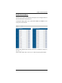
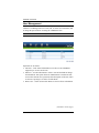
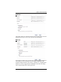
1
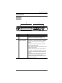
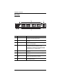
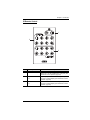
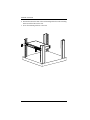
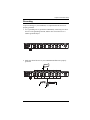
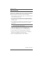
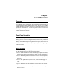
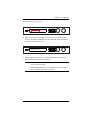
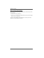
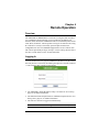
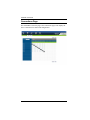
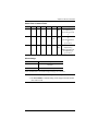
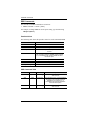
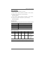
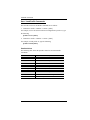
8x8 HDMI Matrix Switch VM0808H User Manual www.aten.com VM0808H User Manual FCC Information This is an FCC Class A product. In a domestic environment this product may cause radio interference in which case the user may be required to take adequate measures. This equipment has been tested and found to comply with the limits for a Class A digital device, pursuant to Part 15 of the FCC Rules. These limits are designed to provide reasonable protection against harmful interference when the equipment is operated in a commercial environment. This equipment generates, uses and can radiate radio frequency energy and, if not installed and used in accordance with the instruction manual, may cause harmful interference to radio communications. Operation of this equipment in a residential area is likely to cause harmful interference in which case the user will be required to correct the interference at his own expense. RoHS This product is RoHS compliant. Safety This product has been classified as Information Technology Equipment. SJ/T 11364-2006 The following contains information that relates to China. ii VM0808H User Manual User Information Online Registration Be sure to register your product at our online support center: International http://support.aten.com North America http://www.aten-usa.com/product_registration Telephone Support For telephone support, call this number: International 886-2-8692-6959 China 86-10-5255-0110 Japan 81-3-5615-5811 Korea 82-2-467-6789 North America 1-888-999-ATEN ext 4988 United Kingdom 44-8-4481-58923 User Notice All information, documentation, and specifications contained in this manual are subject to change without prior notification by the manufacturer. The manufacturer makes no representations or warranties, either expressed or implied, with respect to the contents hereof and specifically disclaims any warranties as to merchantability or fitness for any particular purpose. Any of the manufacturer's software described in this manual is sold or licensed as is. Should the programs prove defective following their purchase, the buyer (and not the manufacturer, its distributor, or its dealer), assumes the entire cost of all necessary servicing, repair and any incidental or consequential damages resulting from any defect in the software. The manufacturer of this system is not responsible for any radio and/or TV interference caused by unauthorized modifications to this device. It is the responsibility of the user to correct such interference. The manufacturer is not responsible for any damage incurred in the operation of this system if the correct operational voltage setting was not selected prior to operation. PLEASE VERIFY THAT THE VOLTAGE SETTING IS CORRECT BEFORE USE. iii VM0808H User Manual Package Contents The VM0808H package consists of: 1 VM0808H 8x8 HDMI Matrix Switch 1 Power Cord 1 IR Remote Control 1 IR Receiver 1 Mounting Kit 1 User Instructions* Check to make sure that all the components are present and that nothing got damaged in shipping. If you encounter a problem, contact your dealer. Read this manual thoroughly and follow the installation and operation procedures carefully to prevent any damage to the unit, and/or any of the devices connected to it. * Features may have been added to the VM0808H since this manual was printed. Please visit our website to download the most up-to-date version. © Copyright 2010–2012 ATEN® International Co., Ltd. Manual Part No. PAPE-0349-AT1G Manual Date: 2012-05-21 ATEN and the ATEN logo are registered trademarks of ATEN International Co., Ltd. All rights reserved. All other brand names and trademarks are the registered property of their respective owners. iv VM0808H User Manual Contents FCC Information . . . . . . . . . . . . . . . . . . . . . . . . . . . . . . . . . . . . . . . . . . . . . ii RoHS. . . . . . . . . . . . . . . . . . . . . . . . . . . . . . . . . . . . . . . . . . . . . . . . . . . . . . ii Safety . . . . . . . . . . . . . . . . . . . . . . . . . . . . . . . . . . . . . . . . . . . . . . . . . . . . . ii SJ/T 11364-2006. . . . . . . . . . . . . . . . . . . . . . . . . . . . . . . . . . . . . . . . . . . . . ii User Information . . . . . . . . . . . . . . . . . . . . . . . . . . . . . . . . . . . . . . . . . . . . .iii Online Registration . . . . . . . . . . . . . . . . . . . . . . . . . . . . . . . . . . . . . . . .iii Telephone Support . . . . . . . . . . . . . . . . . . . . . . . . . . . . . . . . . . . . . . . .iii User Notice . . . . . . . . . . . . . . . . . . . . . . . . . . . . . . . . . . . . . . . . . . . . . .iii Package Contents . . . . . . . . . . . . . . . . . . . . . . . . . . . . . . . . . . . . . . . . . . iv Contents . . . . . . . . . . . . . . . . . . . . . . . . . . . . . . . . . . . . . . . . . . . . . . . . . . . v About this Manual . . . . . . . . . . . . . . . . . . . . . . . . . . . . . . . . . . . . . . . . . .viii Conventions . . . . . . . . . . . . . . . . . . . . . . . . . . . . . . . . . . . . . . . . . . . . . . . ix Product Information. . . . . . . . . . . . . . . . . . . . . . . . . . . . . . . . . . . . . . . . . . ix 1. Introduction Overview . . . . . . . . . . . . . . . . . . . . . . . . . . . . . . . . . . . . . . . . . . . . . . . . . . . 1 Features . . . . . . . . . . . . . . . . . . . . . . . . . . . . . . . . . . . . . . . . . . . . . . . . . . . 2 Requirements . . . . . . . . . . . . . . . . . . . . . . . . . . . . . . . . . . . . . . . . . . . . . . . 3 Source Devices . . . . . . . . . . . . . . . . . . . . . . . . . . . . . . . . . . . . . . . . . . 3 Display Devices . . . . . . . . . . . . . . . . . . . . . . . . . . . . . . . . . . . . . . . . . . 3 Cables . . . . . . . . . . . . . . . . . . . . . . . . . . . . . . . . . . . . . . . . . . . . . . . . . 3 Source Device Operating Systems . . . . . . . . . . . . . . . . . . . . . . . . . . . 4 Components . . . . . . . . . . . . . . . . . . . . . . . . . . . . . . . . . . . . . . . . . . . . . . . . 5 Front View . . . . . . . . . . . . . . . . . . . . . . . . . . . . . . . . . . . . . . . . . . . . . . 5 Rear View . . . . . . . . . . . . . . . . . . . . . . . . . . . . . . . . . . . . . . . . . . . . . . . 6 IR Remote Control . . . . . . . . . . . . . . . . . . . . . . . . . . . . . . . . . . . . . . . . 7 2. Hardware Setup Rack Mounting . . . . . . . . . . . . . . . . . . . . . . . . . . . . . . . . . . . . . . . . . . . . . . 9 Grounding . . . . . . . . . . . . . . . . . . . . . . . . . . . . . . . . . . . . . . . . . . . . . . . . 11 Cable Connection . . . . . . . . . . . . . . . . . . . . . . . . . . . . . . . . . . . . . . . . . . . 12 Installation Diagram . . . . . . . . . . . . . . . . . . . . . . . . . . . . . . . . . . . . . . 13 3. Local Operation Overview . . . . . . . . . . . . . . . . . . . . . . . . . . . . . . . . . . . . . . . . . . . . . . . . . . 15 Front Panel Operation. . . . . . . . . . . . . . . . . . . . . . . . . . . . . . . . . . . . . . . . 15 Basic Navigation . . . . . . . . . . . . . . . . . . . . . . . . . . . . . . . . . . . . . . . . . 15 Menu Organization . . . . . . . . . . . . . . . . . . . . . . . . . . . . . . . . . . . . . . . 16 Enter Password . . . . . . . . . . . . . . . . . . . . . . . . . . . . . . . . . . . . . . . . . 17 Main Page . . . . . . . . . . . . . . . . . . . . . . . . . . . . . . . . . . . . . . . . . . . . . 18 Profiles. . . . . . . . . . . . . . . . . . . . . . . . . . . . . . . . . . . . . . . . . . . . . . 18 Video In Selection . . . . . . . . . . . . . . . . . . . . . . . . . . . . . . . . . . . . . 18 Set IP Port . . . . . . . . . . . . . . . . . . . . . . . . . . . . . . . . . . . . . . . . . . . . . 19 v VM0808H User Manual IP Address . . . . . . . . . . . . . . . . . . . . . . . . . . . . . . . . . . . . . . . . . . . 19 Subnet Mask . . . . . . . . . . . . . . . . . . . . . . . . . . . . . . . . . . . . . . . . . 20 Gateway . . . . . . . . . . . . . . . . . . . . . . . . . . . . . . . . . . . . . . . . . . . . 20 Default IP Settings. . . . . . . . . . . . . . . . . . . . . . . . . . . . . . . . . . . . . 21 Save and Reset / Exit . . . . . . . . . . . . . . . . . . . . . . . . . . . . . . . . . . 21 Set Serial Port . . . . . . . . . . . . . . . . . . . . . . . . . . . . . . . . . . . . . . . . . . 22 Default Serial Settings . . . . . . . . . . . . . . . . . . . . . . . . . . . . . . . . . . 22 Baud Rate . . . . . . . . . . . . . . . . . . . . . . . . . . . . . . . . . . . . . . . . . . . 23 Operation Mode . . . . . . . . . . . . . . . . . . . . . . . . . . . . . . . . . . . . . . . . . 24 Power on Detection . . . . . . . . . . . . . . . . . . . . . . . . . . . . . . . . . . . . 24 EDID . . . . . . . . . . . . . . . . . . . . . . . . . . . . . . . . . . . . . . . . . . . . . . . 25 Security Mode . . . . . . . . . . . . . . . . . . . . . . . . . . . . . . . . . . . . . . . . . . 26 Password Settings. . . . . . . . . . . . . . . . . . . . . . . . . . . . . . . . . . . . . 26 Save / Load Profile . . . . . . . . . . . . . . . . . . . . . . . . . . . . . . . . . . . . . . . 28 IR Remote Control Operation . . . . . . . . . . . . . . . . . . . . . . . . . . . . . . . . . 29 Change the Input source of an Output display . . . . . . . . . . . . . . . . . . 29 Power on/off individual Output displays . . . . . . . . . . . . . . . . . . . . . . . 29 Power on/off all Output displays . . . . . . . . . . . . . . . . . . . . . . . . . . . . . 30 4. Remote Operation Overview. . . . . . . . . . . . . . . . . . . . . . . . . . . . . . . . . . . . . . . . . . . . . . . . . . 31 Logging In . . . . . . . . . . . . . . . . . . . . . . . . . . . . . . . . . . . . . . . . . . . . . . . . . 31 Connections Page . . . . . . . . . . . . . . . . . . . . . . . . . . . . . . . . . . . . . . . . . . 32 Toolbar . . . . . . . . . . . . . . . . . . . . . . . . . . . . . . . . . . . . . . . . . . . . . . . . 33 Configuring Connections . . . . . . . . . . . . . . . . . . . . . . . . . . . . . . . . . . 34 Status Colors . . . . . . . . . . . . . . . . . . . . . . . . . . . . . . . . . . . . . . . . . 34 Save / Load Connection Profiles . . . . . . . . . . . . . . . . . . . . . . . . . . . . 35 Viewing Port Information . . . . . . . . . . . . . . . . . . . . . . . . . . . . . . . . . . 35 Setup . . . . . . . . . . . . . . . . . . . . . . . . . . . . . . . . . . . . . . . . . . . . . . . . . . . . 36 IP Setup . . . . . . . . . . . . . . . . . . . . . . . . . . . . . . . . . . . . . . . . . . . . . . . 36 Serial Setup . . . . . . . . . . . . . . . . . . . . . . . . . . . . . . . . . . . . . . . . . . . . 37 Port Name . . . . . . . . . . . . . . . . . . . . . . . . . . . . . . . . . . . . . . . . . . . . . 38 Firmware . . . . . . . . . . . . . . . . . . . . . . . . . . . . . . . . . . . . . . . . . . . . . . . . . 39 Profile Selection . . . . . . . . . . . . . . . . . . . . . . . . . . . . . . . . . . . . . . . . . . . . 40 Add/Delete Selection Profile . . . . . . . . . . . . . . . . . . . . . . . . . . . . . . . . 40 Profile Selection Name . . . . . . . . . . . . . . . . . . . . . . . . . . . . . . . . . . . . 41 User Management . . . . . . . . . . . . . . . . . . . . . . . . . . . . . . . . . . . . . . . . . . 42 Add User . . . . . . . . . . . . . . . . . . . . . . . . . . . . . . . . . . . . . . . . . . . . . . . 43 Edit User . . . . . . . . . . . . . . . . . . . . . . . . . . . . . . . . . . . . . . . . . . . . . . . 43 Privileges . . . . . . . . . . . . . . . . . . . . . . . . . . . . . . . . . . . . . . . . . . . . . . 44 5. RS-232 Commands Serial Control Protocol Commands . . . . . . . . . . . . . . . . . . . . . . . . . . . . . 45 Configuring the Serial Port . . . . . . . . . . . . . . . . . . . . . . . . . . . . . . . . . 45 Switch Port Commands: . . . . . . . . . . . . . . . . . . . . . . . . . . . . . . . . . . . 45 EDID Commands: . . . . . . . . . . . . . . . . . . . . . . . . . . . . . . . . . . . . . . . . 48 vi VM0808H User Manual Mute Commands: . . . . . . . . . . . . . . . . . . . . . . . . . . . . . . . . . . . . . . . . 49 Save / Load Profile Commands: . . . . . . . . . . . . . . . . . . . . . . . . . . . . . 50 Power On Detection Commands . . . . . . . . . . . . . . . . . . . . . . . . . . . . . 51 Appendix Safety Instructions. . . . . . . . . . . . . . . . . . . . . . . . . . . . . . . . . . . . . . . . . . . 53 General . . . . . . . . . . . . . . . . . . . . . . . . . . . . . . . . . . . . . . . . . . . . . . . . 53 Rack Mounting . . . . . . . . . . . . . . . . . . . . . . . . . . . . . . . . . . . . . . . . . . 55 Technical Support . . . . . . . . . . . . . . . . . . . . . . . . . . . . . . . . . . . . . . . . . . 56 International . . . . . . . . . . . . . . . . . . . . . . . . . . . . . . . . . . . . . . . . . . . . 56 North America . . . . . . . . . . . . . . . . . . . . . . . . . . . . . . . . . . . . . . . . . . 56 Specifications . . . . . . . . . . . . . . . . . . . . . . . . . . . . . . . . . . . . . . . . . . . . . . 57 Limited Warranty . . . . . . . . . . . . . . . . . . . . . . . . . . . . . . . . . . . . . . . . . . . . 58 vii VM0808H User Manual About this Manual This User Manual is provided to help you get the most from your VM0808H system. It covers all aspects of installation, configuration and operation. An overview of the information found in the manual is provided below. Chapter 1, Introduction, introduces you to the VM0808H system. Its purpose, features and benefits are presented, and its front and back panel components are described. Chapter 2, Hardware Setup, describes how to set up your VM0808H installation. Chapter 3, Local Operation, explains the fundamental concepts involved in operating the VM0808H at the local site via the front panel LCD display, using tuner dials, pushbuttons, and the IR remote control. Chapter 4, Remote Operation, provides a complete description of the VM0808H's Browser Graphical User Interface (GUI), and how to use it to remotely configure and operate the VM0808H. Chapter 5, RS-232 Protocol Commands, provides a complete list of the serial control protocol commands used when utilizing the RS-232 Serial Port so that an extra source device can function further as transmitter and receiver. An Appendix, provides specifications and other technical information regarding the VM0808H. viii VM0808H User Manual Conventions This manual uses the following conventions: Monospaced Indicates text that you should key in. [] Indicates keys you should press. For example, [Enter] means to press the Enter key. If keys need to be chorded, they appear together in the same bracket with a plus sign between them: [Ctrl+Alt]. 1. Numbered lists represent procedures with sequential steps. ♦ Bullet lists provide information, but do not involve sequential steps. → Indicates selecting the option (on a menu or dialog box, for example), that comes next. For example, Start → Run means to open the Start menu, and then select Run. Indicates critical information. Product Information For information about all ATEN products and how they can help you connect without limits, visit ATEN on the Web or contact an ATEN Authorized Reseller. Visit ATEN on the Web for a list of locations and telephone numbers: International http://www.aten.com North America http://www.aten-usa.com ix VM0808H User Manual This Page Intentionally Left Blank x Chapter 1 Introduction Overview The ATEN VanCryst VM0808H 8x8 HDMI Matrix Switch is a distinct HDMI solution that offers an easy and affordable way to route any of 8 HDMI video sources to any of 8 HDMI displays, and view them in any arrangement. As a matrix switch the VM0808H allows eight HDMI source devices to cross connect to eight HDMI displays at the same time, while giving you independent input/output control of each in any array possible. The VM0808H gives the ultimate flexibility and control for any HDMI multi-display installation. Convenient configuration and operation is done via Graphical User Interface (GUI) using any web browser, locally by front panel LCD display with easy to use tuner dials, pushbuttons and IR Remote Control, or via high-end system controllers using the built in RS-232 serial controller. The VM0808H unit can be controlled over a standard TCP/IP connection, and seamlessly integrates with any existing network for easy remote access. Furthermore, for complete system integration, RS-232 control is standard with the VM0808H’s built-in bi-directional RS-232 serial port that allows the switch to be controlled through a high-end controller, PC, and/or home automation/home theater software package. With easy operation, simple setup, dynamic display, and convenient control features the VM0808H is the only HDMI solution that gives a multi-display installation everything it needs. 1 VM0808H User Manual Features Connects any of 8 HDMI sources to any of 8 HDMI displays Long Distance Transmission - supports up to 20 meters (24 AWG HDMI standard cable) HDMI (3D, Deep Color) and HDCP compatible Easily switch between multiple sources and multiple displays Local Operation: Front panel LCD display Tuner Dials and Pushbuttons IR Remote Control Serial controller Remote Operation: Browser Graphical User Interface (GUI) Superior video quality – HDTV resolution of 480p, 720p, 1080i, and 1080p (1920 x 1080), VGA, SVGA, SXGA, UXGA and WUXGA (1920 x 1200) Supports Dolby True HD and DTS HD Master audio Signaling rates up to 2.25 Gbits in support of 1080p display Feature EDID Expert technology to set up different configurations via different EDID modes Power on Detection - If an HDMI source is powered off, the VM0808H can automatically switch to the next powered-on source Firmware upgradeable Rack Mountable 2 Chapter 1. Introduction Requirements The following equipment is required for a complete VM0808H installation: Source Devices HDMI Type A output connector(s) Note: A DVI/HDMI adapter is required when connecting a DVI source device. Display Devices Display devices or receivers with an HDMI Type A input connector Cables 1 HDMI cable for each source device you will be connecting. 1 HDMI cable for each display device you will be connecting. Note: No cables are included in this package. We strongly recommend that you purchase high-quality cables of appropriate length since this will affect the quality of the audio and video display. Contact your dealer to purchase the correct cable sets. 3 VM0808H User Manual Source Device Operating Systems Supported operating systems are shown in the table, below: OS Windows Linux UNIX Novell Version 2000 and higher RedHat 6.0 and higher SuSE 8.2 and higher Mandriva (Mandrake) 9.0 and higher AIX 4.3 and higher FreeBSD 3.51 and higher Sun Solaris 8 and higher Netware 5.0 and higher Mac OS 9 and higher DOS 6.2 and higher 4 Chapter 1. Introduction Components Front View 2 1 No. Component MENU ESC PROFILE ENTER OUT IN Description 1 LCD Display The LCD display shows the various options for configuring and operating the VM0808H. For full details, see Front Panel Operation, page 15. 2 Front Panel Tuner Dials & Pushbuttons Use the tuner dials and pushbuttons to navigate the LCD display to configure and operate the VM0808H. MENU – Press to invoke the Menu page/Main Screen PROFILE – Press to switch between the video source Profile Selection list ESC – Press to cancel the current selection or exit without saving changes ENTER – Press to confirm the current selection Tuner Dials - IN & OUT to navigate up, down, left, and right or scroll selected options within the LCD display. For full details, see Front Panel Operation, page 15. Note: The MENU and PROFILE front panel pushbuttons have built-in LEDs that light to indicate they have been selected. 5 VM0808H User Manual Rear View 6 3 1 No. 6 7 4 8 2 5 Component Description 1 Power Socket This is a standard 3-pin AC power socket. The power cord from an AC source plugs in here. 2 Power Switch This is a standard rocker switch that powers the unit on and off. 3 Grounding Terminal The grounding wire attaches here. See Grounding, page 11, for further details. 4 Ethernet Port In order to access the VM0808H’s Browser Graphical User Interface (GUI), the VM0808H must be connected to your network. The cable that connects the VM0808H to your LAN plugs in here. See Cable Connection, page 12, for further details 5 HDMI Input Ports The cables from your HDMI source devices plug into these ports. 6 HDMI Output Ports The cables from your HDMI display devices plug into these ports. 7 External IR Receiver Port 3.5 mm Mini Stereo Jack which connects the IR Receiver unit included with your product. 8 RS-232 Serial Port This serial remote port is for input source selection and high-end system control. Chapter 1. Introduction IR Remote Control 1 2 3 No. Component Description 1 Power ON/OFF Use the ON and OFF pushbuttons to turn the Output displays on or off- by individual port, or all ports. (see IR Remote Control Operation, page 29) 2 Output Pushbuttons Output display Pushbutton 1–8 to change an Input source of an Output display. (see IR Remote Control Operation, page 29) 1–8 3 Input Pushbuttons 1–8 Input source Pushbutton 1–8 to change an Input source of an Output display. (see IR Remote Control Operation, page 29) 7 VM0808H User Manual This Page Intentionally Left Blank 8 Chapter 2 Hardware Setup 1. Important safety information regarding the placement of this device is provided on page 53. Please review it before proceeding. 2. Make sure that the power to all devices connected to the installation are turned off. You must unplug the power cords of any computers that have the Keyboard Power On function. Rack Mounting The VM0808H can be mounted in a 19” (1U) system rack. For the most convenient front panel pushbutton configuration and operation at the local site, mount the unit at the front of the rack, as follows: 1. Use the M3 x 8 Phillips head hex screws supplied with the Rack Mount Kit to screw the rack mounting brackets onto the front of the unit. Phillips Head Hex M3 x 8 (Continues on next page.) 9 VM0808H User Manual 2. Position the unit in the front of the rack and align the holes in the mounting brackets with the holes in the rack. 3. Screw the mounting brackets to the rack. 10 Chapter 2. Hardware Setup Grounding To prevent damage to your installation, it is important that all devices are properly grounded. 1. Use a grounding wire to ground the VM0808H by connecting one end of the wire to the grounding terminal, and the other end of the wire to a suitable grounded object. 2. Make sure that all devices in your VM0808H installation are properly grounded. 11 VM0808H User Manual Cable Connection Installation of the VM0808H is simply a matter of connecting the appropriate cables. Refer to the installation diagram on the following page (the numbers in the diagram correspond to the steps below), and do the following: 1. If using the Remote Operation features, plug a Cat-5e cable from the LAN into the VM0808H’s Ethernet port. 2. If you are using the serial control function, use an appropriate RS-232 serial cable to connect the computer or serial controller to the VM0808H’s female RS-232 port. 3. Use a grounding wire to ground the unit by connecting one end of the wire to the grounding terminal, and the other end of the wire to a suitable grounded object. Note: Do not omit this step. Proper grounding helps to prevent damage to the unit from surges or static electricity. 4. Connect up to 8 HDMI video sources to the HDMI Input ports 5. Connect up to 8 HDMI display devices to the HDMI Output ports 6. Connect the IR Receiver into the External IR Receiver Input Port 7. Plug the power cord supplied with the package into the VM0808H’s 3prong AC socket, and then into an AC power source. 8. Power on the VM0808H and all devices in the installation. (Continues on next page.) 12 Chapter 2. Hardware Setup Installation Diagram 5 6 7 1 3 2 4 13 VM0808H User Manual This Page Intentionally Left Blank 14 Chapter 3 Local Operation Overview The VM0808H can be configured and operated locally on the front panel LCD via tuner dials, pushbuttons and IR Remote Control; remotely over a standard TCP/IP connection via graphical user interface (GUI) using a web browser; or by a RS-232 serial controller. The local front panel operation is discussed in this chapter, Over-IP operation is discussed in Chapter 4, and RS-232 serial control is discussed in Chapter 5. Front Panel Operation The VM0808H front panel features pushbuttons, tuner dials, and an LCD display panel for convenient configuration and operation locally. This allows you to perform operations such as selecting which source displays on which display, configuring the IP port, configuring the serial port, setting Power On Detection and EDID modes, selecting security settings, and loading/saving connection profiles. Basic Navigation The VM0808H’s front panel display operation is easy and convenient. Please note the following front panel button and dial operations: Use the MENU pushbutton to access the Menu page options: Set IP Port, Set Serial Port, Operation Mode, Security Mode, and Save/Load Profile. Use the PROFILE pushbutton to switch between the connection profiles which have been added to the Profile Selection list (see Profile Selection, page 40) Use the ESC pushbutton to go back a level, return to the Main page, or exit. Use the ENTER or tuner dial pushbuttons to select options and confirm operations. Use the tuner IN and OUT dials to cycle forward or backward through the menus or options. 15 VM0808H User Manual Menu Organization Use the MENU pushbutton to switch between the Main Screen and Menu page. From the Main screen press the MENU pushbutton to access the Menu page and cycle through the menu options using the tuner dials, starting from Set IP Port, in the order show in the table, below: Menu Page Sub-Menu Page(s) Password Main Page Set IP Port Select Video IN 1-8, or N/A Profile Pressing the front panel PROFILE pushbutton cycles through the connection Profiles added to the Profile Selection list. (See Profile Selection, page 40) IP Address Subnet Mask Save and Reset / Exit Gateway Default IP Settings Yes / No Set Serial Port Default Serial Setting Yes / No Baud Rate 9600 / 19200 / 38400 / 115200 Operation Mode Power On Detection Off / On Security Mode Save / Load Profile EDID Default / Port1 / Remix Password Required Yes / No Change Password Old Password Save to a Profile No 0–31 Call a Saved Profile No 16 New Password Chapter 3. Local Operation Enter Password If the VM0808H has been configured to require a password for local operation (see Security Mode, page 26), the password screen appears when the VM0808H is powered on, and the cursor flashes on the first digit. Enter a 4digit password to continue to the Main Screen. Note: If you are accessing the VM0808H for the first time, the default password is 1234. MENU ESC PROFILE ENTER OUT IN Enter Password: 0000 To enter a password, do the following: 1. Turn the front panel OUT dial left or right to move the cursor position. 2. Turn the front panel IN dial left or right to cycle through the numbers. 3. Press and Release the OUT, IN, or ENTER pushbutton to confirm the password and continue to the Main Screen. Note: 1. If you enter an incorrect password, re-enter the correct password over the incorrect string. 2. If Password Required (see Security Mode, page 26) is enabled, the LCD displays time-out is 5 minutes. 17 VM0808H User Manual Main Page The Main screen displays Output Ports 1–8 in sequential order across the top. The Input source displaying on each Output port is shown directly beneath it. From the Main screen, you can set the Input to Output connections that route the signals from a selected Input port to the selected Output port. To do so you simply change the Input source port associated for each Output display. Profiles From the Main screen; pressing the PROFILE pushbutton switches between the connection profiles added to the Profile Selection list (see Profile Selection, page 40). If a connection profile is in use, it is shown from the main page on the lower right corner of the LCD display. OUTPUT INPUT MENU ESC PROFILE ENTER OUT IN 01 02 03 04 05 06 07 08 01 02 03 04 05 06 07 08 F00 Video In Selection To select which input source displays on each output port, from the main screen do the following: 1. Turn the OUT dial to select an output port’s corresponding input port. OUTPUT INPUT 01 02 03 04 05 06 07 08 01 02 03 [04] 05 06 07 08 MENU ESC PROFILE ENTER OUT IN F00 2. When the cursor [ ] highlights the selected input port you want to change, use the IN dial to cycle through the available input sources. Options are: Ports 1–8, NA (none) 3. Press the OUT, IN, or ENTER pushbutton to confirm your selection. The signal from the selected input port is now tied to the output port above it. 4. Repeat steps 1–3 for all required ports. 18 Chapter 3. Local Operation Set IP Port To configure the VM0808H’s IP port settings, from the Menu page, turn the front panel OUT/IN dial to move the cursor to the Set IP Port position, and use the OUT, IN, or ENTER pushbutton to select Set IP Port. MENU ESC PROFILE ENTER OUT IN Set IP Port Set Serial Port The sub-menu provides four options: IP Address; Subnet Mask; Gateway; and Default IP Settings; as follows: IP Address To set the VM0808H’s IP address, do the following: 1. Select IP Address from the Set IP Port submenu. The cursor flashes on the first number: MENU ESC PROFILE ENTER OUT IN IP Address: 192.168.0.60 Subnet Mask: 255.255.255.0 2. Turn the front panel IN dial left or right to cycle through and change each number. 3. Turn the front panel OUT dial left or right to move [ ] the cursor to each position. 4. Press the OUT, IN, or ENTER pushbutton to confirm the IP address. 5. Press ESC to return to the previous step without change. Note: The default IP address is 192.168.0.60 19 VM0808H User Manual Subnet Mask To set the VM0808H’s Subnet Mask, do the following: 1. Select Subnet Mask from the Set IP Port submenu. The cursor flashes on the first number: MENU ESC PROFILE ENTER OUT IN IP Address: 192.168.0.60 Subnet Mask: 255.255.255.0 2. Turn the front panel IN dial left or right to cycle through and change each number. 3. Turn the front panel OUT dial left or right to move [ ] the cursor to each position. 4. Press the OUT, IN, or ENTER pushbutton to confirm the Subnet Mask. 5. Press ESC to return to the previous step without change. Note: The default Subnet Mask is 255.255.255.0 Gateway To set the VM0808H’s Gateway, do the following: 1. Select Gateway from the Set IP Port submenu. The cursor flashes on the first number: MENU ESC PROFILE ENTER OUT IN Gateway: 192.168.0.1 Default IP Setting: No 2. Turn the front panel IN dial left or right to cycle through and change each number. 3. Turn the front panel OUT dial left or right to move [ ] the cursor to each position. 20 Chapter 3. Local Operation 4. Press the OUT, IN, or ENTER pushbutton to confirm the Gateway. 5. Press ESC to return to the previous step without change. Note: The default Gateway is 192.168.0.1 Default IP Settings To use / not use the VM0808H’s Default IP Settings, do the following: 1. Select Default IP Settings from the Set IP Port submenu. The cursor flashes on the entry: MENU ESC PROFILE ENTER OUT IN Gateway: 192.168.0.1 Default IP Setting: NO 2. Turn the front panel IN dial left or right to select Yes or No. 3. Press and Release the OUT, IN, or ENTER pushbutton to confirm the change. Save and Reset / Exit After each operation, you can either: MENU ESC PROFILE ENTER OUT IN Save and Reset the Device Exit without Save Save and Reset the Device to save all changes and restart the VM0808H; Exit without Save to ignore changes and return to the Menu; or Press ESC to return to the previous step without change. 21 VM0808H User Manual Set Serial Port To configure the VM0808H’s serial port settings, select Set Serial Port from the Menu page. MENU ESC PROFILE ENTER OUT IN Set IP Port Set Serial Port The sub-menu provides two options: Default Serial Settings, and Baud Rate, as follows: Default Serial Settings To use / not use the VM0808H’s Default Serial Settings, do the following: 1. Select Default Serial Settings from the Set Serial Port submenu. The cursor flashes on the entry. MENU ESC PROFILE ENTER OUT IN Default Serial Setting: NO Baud Rate: 19200 2. Turn the front panel IN/OUT dial left or right to select Yes or No. 3. Press and Release the OUT, IN, or ENTER pushbutton to confirm the change. Note: The default serial setting is No. 22 Chapter 3. Local Operation Baud Rate To set the VM0808H’s baud rate, do the following: 1. Select Baud Rate from the Set Serial Port submenu. The cursor flashes on the first number: MENU ESC PROFILE ENTER OUT IN Default Serial Setting: NO Baud Rate: 19200 2. Turn the front panel IN/OUT dial to cycle through the options. Baud Rate options are 9600, 19200, 38400, and 115200. 3. Press and release the OUT, IN, or ENTER pushbutton to confirm the Baud Rate. Note: The default baud rate is 19200. 23 VM0808H User Manual Operation Mode The Power On Detection and EDID features are adjusted from the Operation Mode menu. The Power on Detection mode automatically switches an Output port to the next powered-on source if its video source is powered off. EDID (extended display identification data) is used to automatically or manually setup different video configurations via EDID modes to utilize the best resolution across different monitors. To adjust the Power On Detection or EDID mode, from the Main page do the following: Power on Detection 1. Use the MENU button to access the Menu page, turn the OUT/IN dial to scroll down and select [ENTER] Operation Mode: MENU ESC PROFILE ENTER OUT IN Operation Mode Security Mode 2. With the arrow on Power On Detection, press and release the OUT, IN, or ENTER pushbutton to access the Power On Detection options. MENU ESC PROFILE ENTER OUT IN Power On Detection: ON EDID: Default 3. Turn the front panel OUT/IN dial to cycle through On or Off. 4. Press and Release the OUT, IN, or ENTER pushbutton to confirm the change. 24 Chapter 3. Local Operation EDID 1. Use the MENU button to access the Menu page, turn the OUT/IN dial to scroll down and select [ENTER] Operation Mode: MENU ESC PROFILE ENTER OUT IN Operation Mode Security Mode 2. Turn the IN/OUT dial to move the arrow to the EDID position, and press the OUT, IN, or ENTER pushbutton to select EDID. MENU ESC PROFILE ENTER OUT IN Power on Detection: ON EDID: Default 3. Turn the front panel OUT/IN dial to cycle through the options; Default, Port1, or Remix. 4. Press and Release the OUT, IN, or ENTER pushbutton to confirm the change. EDID Option Description Default The default EDID will be passed to all video sources. Port1 The EDID from port1 will be passed to all video sources. Remix Uses the EDID of each connected display according to its connection when the VM0808H is first powered on, or immediately after pressing ENTER to select the Remix option. Note: The default EDID setting is Default. 25 VM0808H User Manual Security Mode The Security Mode page allows you to configure the VM0808H’s password related settings; Password Required and Change Password. The Password Required option sets the VM0808H to require a password for local operation after the units LCD display times out (default: 5 minutes) or is powered off/on. The Change Password option allows you to set a new password for the VM0808H. Password Settings To configure the VM0808H’s password settings, from the Main screen do the following: 1. Use the MENU button to access the Menu page, turn the OUT/IN dial to scroll down and select [ENTER] Security Mode. MENU ESC PROFILE ENTER OUT IN Operation Mode Security Mode 2. To set the VM0808H to require a password for local operation, select [ENTER] Password Required, and turn the IN/OUT dial to select Yes or No and press the OUT, IN, or ENTER pushbutton to confirm. MENU ESC PROFILE ENTER OUT IN Password Required: YES Change Password 3. To change the password, use the IN/OUT dial to move the arrow to Change Password and press the OUT, IN, or ENTER pushbutton to select. (Continues on next page.) 26 Chapter 3. Local Operation (Continued from previous page.) MENU ESC PROFILE ENTER OUT IN Password Required: YES Change Password 4. Enter the old password (see Enter Password, page 17). Then, press the OUT, IN, or ENTER pushbutton to create a New Password, and enter the new password in the same way. MENU ESC PROFILE ENTER OUT IN Old Password: 1234 New Password: 0000 5. Press and Release the OUT, IN, or ENTER pushbutton to confirm the password and continue to the Main Screen. Note: 1. If you enter an incorrect password, re-enter the correct password over the incorrect string. 2. If Password Required (see Security Mode, page 26) is enabled, the LCD displays time-out is 5 minutes. 27 VM0808H User Manual Save / Load Profile The VM0808H allows you to store up to 32 (numbered 0–31) different connection profiles that can be saved and recalled later. When profiles are saved, they are saved according to the current connection configuration on the Main page. When you load a profile the change is immediate and the profile number is shown in the lower right corner of the LCD display. To save/load profiles, from the Main page do the following: 1. Use the MENU button to access the Menu page, turn the OUT/IN dial to scroll down and select [ENTER] Save/Load Profile. MENU ESC PROFILE ENTER OUT IN Save/Load Profile 2. To save the current connection configuration as a profile, select [ENTER] Save to a Profile No, turn the IN/OUT dial to cycle through the numbers (0–31), and press the OUT, IN, or ENTER pushbutton to save the profile as the number you select. MENU ESC PROFILE ENTER OUT IN Save to a Profile No. 00 Call a saved Profile No. 00 3. To load a saved Profile, select [ENTER] Call a Saved Profile No, turn the IN/OUT dial to cycle through the profiles (0–31) and press the OUT, IN, or ENTER pushbutton to select the profile to load. MENU ESC PROFILE ENTER Save to a Profile No. 00 Call a Saved Profile No. 00 28 OUT IN Chapter 3. Local Operation IR Remote Control Operation The remote control allows you to change the Output port status of each display using the IR remote control device included with your VM0808H. You can use the remote control to: change the Input source of any Output display, power on/off individual Output displays, or power on/off all Output displays simultaneously. Before using the remote control you must first plug the IR External Receiver into the rear of the VM0808H and place the receiver where the IR signal can be reached (see External IR Receiver Port, page 6). Change the Input source of an Output display To change the Input source of an Output display, with the remote control, do the following: 1. Press the OUTPUT port number (1–8) you want to change. 2. Within 2 seconds press the INPUT port number (1–8) you want the OUTPUT port to display.* 3. Repeat steps 1-2 to change additional ports. *For the change to occur the INPUT must be pressed within 2 seconds of pressing the OUTPUT number. Power on/off individual Output displays To power on/off individual Output displays, with the remote control, do the following: 1. Press the OUTPUT port number (1–8) you want to power on/off. 2. Within 2 seconds press the ON or OFF pushbutton.* 3. Repeat steps 1-2 to change the power status back on/off. *If the ON or OFF pushbutton is not pushed within two seconds of pushing the OUTPUT’s port number, all displays will be brought to a powered on or off status, respectively. 29 VM0808H User Manual Power on/off all Output displays To power on/off all Output displays simultaneously, with the remote control, do the following: 1. Press the ON or OFF pushbutton.* 2. Repeat step 1 to simultaneously change back the power status of all Output ports, to on or off, respectively. *The ON or OFF pushbuttons bring all displays to the same power status, regardless of the individual power statuses. 30 Chapter 4 Remote Operation Overview The VM0808H 8x8 HDMI Matrix Switch can be configured and controlled over a standard TCP/IP connection via its own Browser Graphical User Interface (GUI). Because the VM0808H can be accessed from anywhere on the LAN, WAN, or Internet, remote operators can log in via Web browsers using IE 7 and above. Security is ensured by password protection and user configurable time-out. The VM0808H supports three levels of remote users with various operational privileges, and up to 32 users can log into the GUI at one time. For full details, see the sections that follow. Logging In To access the Browser GUI, type the VM0808H’s IP address into the address bar of any browser. If a Security Alert dialog box appears, accept the certificate - it can be trusted. The welcome screen appears: The VM0808H’s default IP address is http://192.168.0.60. See IP Setup, page 36, for further information. The default username and password are: administrator/password. See User Management, page 42, for further information. The same user can not be logged in simultaneously. Note: The VM0808H username supports lower case letters only. 31 VM0808H User Manual Connections Page The VM0808H’s GUI main page is the Connections page. This displays all active connections for control and configuration: 32 Chapter 4. Remote Operation Toolbar Icon Description Connections This page displays the VM0808H’s active connections and enables you to control them. Setup This page enables you to configure the VM0808H’s IP settings, serial settings and port names. Firmware The page enables you to upgrade the VM0808H’s firmware. Profile This page allows you to add, delete and name connection profiles to the Selection Profile List, to use with the front panel PROFILE pushbutton. User Management This page enables you to add, edit and delete- user information, permissions, and passwords. Save/Load Profiles This menu option allows you to save and load stored profiles. Exit This icon ends the session and closes the Web interface. 33 VM0808H User Manual Configuring Connections To configure a connection, from the connections page do the following: 1. Select the radio button at the corresponding intersection of the input/ output ports you want to connect, to connect each input source to an output display. Note: Multiple connections can be changed simultaneously; simply select all the connections you want to configure. 2. Click the Submit button. The display reloads with the new status changes. Or, click the Clear button to revert to the stored configuration. Status Colors Connections display in colors to indicate their status, as follows: Gray – Connected White – Not Connected Note: The latest connections will load automatically when the VM0808H is reset. 34 Chapter 4. Remote Operation Save / Load Connection Profiles The VM0808H allows you to store up to 32 (numbered 00–31) differently configured connection profiles that can be saved and recalled later by either connection method (locally via the unit’s front panel pushbuttons and over IP via the GUI). Use the Save button to save the current connection profile. Use the drop-down list to select a saved connection profile and then click the Load button to switch to that profile. Note: Profile 00 is the default. Viewing Port Information The input ports can be sorted by port name or port number. Use the drop-down menu to select. Move your cursor over the Output Port number to see the port name displayed. See Port Name, page 38, for further information. 35 VM0808H User Manual Setup Click the Setup icon to configure the VM0808H’s IP and serial settings, and to name all the ports in your installation. IP Setup The Web Setup settings enable you to configure the VM0808H’s Web interface connection. Changes take a few seconds and automatically redirect you to the IP address specified. Enter values and then click Save or Clear. Click Default Setting to use the following defaults: IP Address – 192.168.0.60 Subnet Mask – 255.255.255.0 Default Gateway – 192.168.0.1 Website Timeout* – 5 minutes *This option controls how long an inactive web connection stays logged in to the VM0808H. Any changes will take effect immediately. 36 Chapter 4. Remote Operation Serial Setup The Serial Setup settings enable you to configure the VM0808H’s serial connection. Use the drop-down menu to select the value and then click Save or Clear. Click Default Setting to use the following defaults: Baud Rate – 19200 37 VM0808H User Manual Port Name The Port Name page enables Administrators and Super Users to change the display name of the input and output ports. To change the display name, enter a value and click Save. Click Clear to revert to the previous stored name. •Port Name: Input/Output Port Names can be the same. (Enter max 16 Characters, Using: 0-9, a-z, A-Z, _, -). •Input Name: Enter name, Click “save” to name the given port. •Output Name: Enter name, Click “save” to name the given port. 38 Chapter 4. Remote Operation Firmware Click the Firmware icon to view information about the VM0808H’s firmware version and to upgrade. This is an Administrator function only To upgrade the VM0808H’s firmware, do the following: 1. Use the Browse button to locate the firmware upgrade file. 2. Click Upgrade Firmware to start the upgrade. Note: Check the box to enable the utility to compare the VM0808H’s current firmware version with that of the upgrade files. If it finds that the VM0808H’s firmware version is the same or higher than the selected upgrade version, it brings up a dialog box informing you of the situation and gives you the option to Continue or Cancel. 39 VM0808H User Manual Profile Selection The profile selection page allows you to set a series of connections profiles, that can be cycled through using the front panel PROFILE pushbutton. Once you have added connection profiles to the Profile Selection List, you can press the front panel PROFILE pushbutton to switch between the profiles which have been added to the Profile List. Click the Profile icon to add, delete, or name connection profiles to the Profile Selection List. Add/Delete Selection Profile To Add a profile to the Profile List, do the following: 1. From the Profile drop-down menu, select the connection profile (00-31) you want to add. 2. Click the Add button. By default new profiles are added to the bottom of the Profile List. To Delete a connection profile from the Profile List, do the following: 1. Select the radio button of the profile you want to delete. 2. Click the Delete button. 40 Chapter 4. Remote Operation Profile Selection Name The Name page enables Administrators and Super Users to change the name of the selection profiles in the profile list. To change the display name, enter a value and click Save. Click Clear to revert to the previous stored name. •Profile Name: Names can be the same. (Enter max 16 Characters, Using: 0-9, a-z, A-Z, _, -). •Profile Name: Enter name, Click “save” to name the given profile number. 41 VM0808H User Manual User Management Click the User Management icon to add, edit, or delete user information, and to change the passwords for accessing the VM0808H’s GUI. Note: This is an Administrator only function. Operations are as follows: Add User – Click Add to add another user to the list. The VM0808H supports up to 32 users at one time. Edit User – Use the radio button to select a user and click Edit to change the information. This option allows an Administrator to rename the user, set/reset the selected user’s password, add a description of the user, and to set the user’s privileges. See below for full details. Delete User – Select user and click Delete to remove all user information. (Continues on next page.) 42 Chapter 4. Remote Operation Add User Click Add, to add a user, fill in the username, password, description, select the appropriate privileges (see Privileges, page 44), and click Submit. Edit User Use this page to rename a user, set/reset a user’s password, add a description of a user, and to set a user’s privileges for accessing the VM0808H’s GUI. Usernames and passwords are case sensitive, and must be 5–16 alphanumeric characters. If a user is logged into the VM0808H’s GUI, their user settings can’t be edited, and the boxes will be grayed out. 43 VM0808H User Manual Privileges Use the Edit User function to set a user’s privileges. The three available levels are as follows: Administrator – this level provides full access and control of the VM0808H functions in addition to full User Management privileges Super User – this level provides full access and control with no User Management privileges User – this level provides basic functions only (create connections, save and recall presets) 44 Chapter 5 RS-232 Commands Serial Control Protocol Commands This chapter provides a complete list of the serial control protocol commands used when utilizing the RS-232 Serial Port so that an extra source device can function further as transmitter and receiver. Configuring the Serial Port The controller’s serial port should be configured as follows: RS-232 Serial Control Protocol Settings Baud Rate 19200 (Default) Data Bit 8 bits Parity None Stop Bit 1 Bit Flow Control None Switch Port Commands: The formulas for Switch Port commands are as follows: 1. Switch Command + Input Command + Port number + Output Command + Port Number + Control + [Enter] For example, to switch input port 02 to output port 05, type the following: sw i02 o05 [Enter] 2. Switch Command + Output Command + Port Number + Control + [Enter] For example, to turn off output on port 03, type the following: sw o03 off [Enter] 3. Switch Command + Output Command + Port Number + Control + [Enter] For example, to switch output port 04 to the next port, type the following: sw o04 + [Enter] 45 VM0808H User Manual Possible Values The following table shows the possible values for switch commands: Command sw Description Switch command Input Command i Description Input command Input Port Number xx Description 01-08 port (default is 01) Output Command o Description Output Command Output Port Number yy * Description 01-08 port (default is 01) All output ports Control 46 Description on Turn on off Turn off + Next port - Previous port Enter Description [Enter] Enter and send out the command Chapter 5. RS-232 Commands Switch Port Command Table: Cmd In N1 Out N2 sw i xx o yy C2 * Enter Description Enter Key Switch Input Port xx to Output Port yy (xx:01~08; yy:01~08, *) sw o yy on * off Enter Key Turn on Output Port yy Turn off Output Port yy (yy:01~08, *) sw o yy + * - Enter Key Switch Next Input to Output Port yy Switch Previous Input to Output Port yy (yy:01~08, *) Acknowledge: Ack Description Command OK Command is correct and function executed Command Incorrect Unavailable command or parameters After commands are sent acknowledge messages are returned. Note: 1. Each command string can be separated with a space. 2. The Port Number command string can be skipped, and the default value will be used. 47 VM0808H User Manual EDID Commands: The formulas for EDID commands are as follows: 1. EDID Command + Control + [Enter] For example, to change EDID to use the port1 setting, type the following: edid port1 [Enter] Possible Values The following table shows the possible values for switch commands:EDID Command Description edid EDID mode selection Control Description port1 The EDID from port1 will be passed to all video sources. remix Uses the EDID of each connected display according to its connection when the VM0808H is first powered on, or immediately after pressing ENTER to select the Remix option. default The default EDID will be passed to all video sources. Enter Description [Enter Key] Send out command EDID Command Table Command Control Enter Description edid port1 [Enter Key] The EDID from port1 will be passed to all video sources. edid remix [Enter Key] Uses the EDID of each connected display according to its connection when the VM0808H is first powered on, or immediately after pressing ENTER to select the Remix option. edid default [Enter Key] The default EDID will be passed to all video sources. 48 Chapter 5. RS-232 Commands Mute Commands: The formulas for Mute commands are as follows: 1. Mute Command + Output Command + Port Number + Control + [Enter] For example, to mute output port 05, type the following: mute o05 on [Enter] 2. Mute Command + Output Command + Port Number + Control + [Enter] For example, turn on audio at output port 05, type the following: mute o05 off [Enter] Possible Values The following table shows the possible values for mute commands:Commands Command mute Description Mute selected output port Control Description on Mute on; audio from selected output port is disabled off Mute off; audio output enabled (default) Mute Command Table Command Output Num2 Control Enter Description mute o yy on [Enter Key] Mute Output Port yy (yy:01~08, *) (Default: *) mute o yy off [Enter Key] Turn on Audio at Output Port yy (yy:01~08, *) (Default: *) Note:Each command string can be separated with a space. 49 VM0808H User Manual Save / Load Profile Commands: The formulas for Save/Load Profile commands are as follows: 1. Command + Profile + Number + Control + [Enter] For example, to save the current connection configuration to profile 12, type the following: profile f 12 save [Enter] 2. Command + Profile + Number + Control + [Enter] For example, to load profile 12, type the following: profile f 12 load [Enter] Possible Values The following table shows the possible values for Save/load Profile commands: Command profile Description Save / Load profile Profile f Description Profile Profile Number yy Control 50 Description 00-31 (default is 00) Description save Save the current connection configuration load Load a saved profile Chapter 5. RS-232 Commands Profile Command Table: Command Profile Num1 Control Enter Description profile f yy save [Enter Key] Save current connection configuration to profile yy (yy:00~31) (Default: 00) profile f yy load [Enter Key] Load saved profile yy (yy:00~31) Default: 00) Acknowledge: Ack Description Command OK Command is correct and function executed Command Incorrect Unavailable command or parameters After commands are sent acknowledge messages are returned. Power On Detection Commands The formula for the Power On Detection command is as follows: 1. Command + Control [Enter] For example, to turn off the Power On Detection feature, input the following: pod off [Enter] Possible Values The following tables show the possible values for the Power on Detection commands: Command pod Description Power On Detection function Control Description on Enable power on detection function off Disable power on detection function 51 VM0808H User Manual Power on Detection Command Table: Command Control Enter Description pod on [Enter] Turn on power on detection (default) pod off [Enter] Turn on power off detection Acknowledge: Ack Description Command OK Command is correct and function executed Command Incorrect Unavailable command or parameters After commands are sent acknowledge messages are returned. 52 Appendix Safety Instructions General Read all of these instructions. Save them for future reference. Follow all warnings and instructions marked on the device. Do not place the device on any unstable surface (cart, stand, table, etc.). If the device falls, serious damage will result. Do not use the device near water. Do not place the device near, or over, radiators or heat registers. The device cabinet is provided with slots and openings to allow for adequate ventilation. To ensure reliable operation, and to protect against overheating, these openings must never be blocked or covered. The device should never be placed on a soft surface (bed, sofa, rug, etc.) as this will block its ventilation openings. Likewise, the device should not be placed in a built in enclosure unless adequate ventilation has been provided. Never spill liquid of any kind on the device. Unplug the device from the wall outlet before cleaning. Do not use liquid or aerosol cleaners. Use a damp cloth for cleaning. The device should be operated from the type of power source indicated on the marking label. If you are not sure of the type of power available, consult your dealer or local power company. The device is designed for IT power distribution systems with 230V phase-to-phase voltage. To prevent damage to your installation it is important that all devices are properly grounded. The device is equipped with a 3-wire grounding type plug. This is a safety feature. If you are unable to insert the plug into the outlet, contact your electrician to replace your obsolete outlet. Do not attempt to defeat the purpose of the grounding-type plug. Always follow your local/national wiring codes. Do not allow anything to rest on the power cord or cables. Route the power cord and cables so that they cannot be stepped on or tripped over. 53 VM0808H User Manual If an extension cord is used with this device make sure that the total of the ampere ratings of all products used on this cord does not exceed the extension cord ampere rating. Make sure that the total of all products plugged into the wall outlet does not exceed 15 amperes. To help protect your system from sudden, transient increases and decreases in electrical power, use a surge suppressor, line conditioner, or un-interruptible power supply (UPS). Position system cables and power cables carefully; Be sure that nothing rests on any cables. Never push objects of any kind into or through cabinet slots. They may touch dangerous voltage points or short out parts resulting in a risk of fire or electrical shock. Do not attempt to service the device yourself. Refer all servicing to qualified service personnel. If the following conditions occur, unplug the device from the wall outlet and bring it to qualified service personnel for repair. The power cord or plug has become damaged or frayed. Liquid has been spilled into the device. The device has been exposed to rain or water. The device has been dropped, or the cabinet has been damaged. The device exhibits a distinct change in performance, indicating a need for service. The device does not operate normally when the operating instructions are followed. Only adjust those controls that are covered in the operating instructions. Improper adjustment of other controls may result in damage that will require extensive work by a qualified technician to repair. 54 Appendix Rack Mounting Before working on the rack, make sure that the stabilizers are secured to the rack, extended to the floor, and that the full weight of the rack rests on the floor. Install front and side stabilizers on a single rack or front stabilizers for joined multiple racks before working on the rack. Always load the rack from the bottom up, and load the heaviest item in the rack first. Make sure that the rack is level and stable before extending a device from the rack. Do not overload the AC supply branch circuit that provides power to the rack. The total rack load should not exceed 80 percent of the branch circuit rating. Make sure that all equipment used on the rack – including power strips and other electrical connectors – is properly grounded. Ensure that proper airflow is provided to devices in the rack. Ensure that the operating ambient temperature of the rack environment does not exceed the maximum ambient temperature specified for the equipment by the manufacturer. Do not step on or stand on any device when servicing other devices in a rack. 55 VM0808H User Manual Technical Support International For online technical support – including troubleshooting, documentation, and software updates: http://support.aten.com For telephone support, see Telephone Support, page iii: North America Email Support Online Technical Support [email protected] Troubleshooting Documentation Software Updates Telephone Support http://www.aten-usa.com/support 1-888-999-ATEN ext 4988 When you contact us, please have the following information ready beforehand: Product model number, serial number, and date of purchase. Your computer configuration, including operating system, revision level, expansion cards, and software. Any error messages displayed at the time the error occurred. The sequence of operations that led up to the error. Any other information you feel may be of help. 56 Appendix Specifications Function Connectors HDMI In 8 x HDMI Type A Female (Black) HDMI Out 8 x HDMI Type A Female (Black) Ethernet 1 x RJ-45 Female RS-232 1 x DB-9 Female (Black) IR Input Port Power Switches LEDs 1 x 3-prong AC Socket 1 x Tuner Button Out 1 x Tuner Button Esc 1 x Pushbutton Menu 1 x Pushbutton Profile 1 x Pushbutton Enter 1 x Pushbutton Power 1 x Rocker Menu 1 (Green) Profile 1 (Green) 100–240VAC; 50-60Hz; 1A Power Consumption Operating Temp. Storage Temp. Humidity Physical Properties 1 x Mini Stereo Jack Female (Black) In I/P Rating Environment VM0808H 120V / 32W; 230V / 34W 0–50ºC -20–60ºC 0–80% RH, Non-condensing Housing Metal Weight 4.01 kg Dimensions (L x W x H) 43.24 x 27.12 x 4.40 cm 57 VM0808H User Manual Limited Warranty IN NO EVENT SHALL THE DIRECT VENDOR'S LIABILITY EXCEED THE PRICE PAID FOR THE PRODUCT FROM DIRECT, INDIRECT, SPECIAL, INCIDENTAL, OR CONSEQUENTIAL DAMAGES RESULTING FROM THE USE OF THE PRODUCT, DISK, OR ITS DOCUMENTATION. The direct vendor makes no warranty or representation, expressed, implied, or statutory with respect to the contents or use of this documentation, and especially disclaims its quality, performance, merchantability, or fitness for any particular purpose. The direct vendor also reserves the right to revise or update the device or documentation without obligation to notify any individual or entity of such revisions, or update. For further inquiries, please contact your direct vendor. 58