1
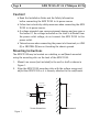
INSTALLATION GUIDE AXIS T8125 AC 24 V Midspan 60 W ENGLISH Legal Considerations Australia - This digital equipment fulfills the requirements for RF emission according to the Class B limit of AS/NZS CISPR 22. Electromagnetic Compatibility (EMC) Korea - ࢇ̛̛Еɼࢽࡈ%̗ࢷળࢶଢ̛̛Ի۰ ࣯Իɼࢽ߾۰ࡈیଜЕʨࡶּࢶࡳԻଜֲֻҘ एࠇ߾۰ࡈیଟܹݡТЬ Video and audio surveillance can be prohibited by laws that vary from country to country. Check the laws in your local region before using this product for surveillance purposes. This equipment has been designed and tested to fulfill applicable standards for: • Radio frequency emission when installed according to the instructions and used in its intended environment. • Immunity to electrical and electromagnetic phenomena when installed according to the instructions and used in its intended environment. USA - This equipment has been tested using a shielded network cable (STP) and found to comply with the limits for a Class B digital device, pursuant to part 15 of the FCC Rules. These limits are designed to provide reasonable protection against harmful interference in a residential installation. This equipment generates, uses and can radiate radio frequency energy and, if not installed and used in accordance with the instructions, may cause harmful interference to radio communications. However, there is no guarantee that interference will not occur in a particular installation. If this equipment does cause harmful interference to radio or television reception, which can be determined by turning the equipment off and on, the user is encouraged to try to correct the interference by one or more of the following measures: • Reorient or relocate the receiving antenna. • Increase the separation between the equipment and receiver. • Connect the equipment into an outlet on a circuit different from that to which the receiver is connected. • Consult the dealer or an experienced radio/TV technician for help. Europe - This digital equipment fulfills the requirements for RF emission according to the Class B limit of EN 55022. This product fulfills the requirements for immunity according to EN 55024 residential and commercial environments. Canada - This Class B digital apparatus complies with Canadian ICES-003. Japan - この装置は、クラスB 情報技術装置です。 この装置は、家庭環境で使用することを目 的として いますが、この装置がラジオやテレビジョン受信機 に近接して使用されると、 受信障害を引き起こすこ とがあります。 取扱説明書に従って正しい取り扱い をして下さい。 Safety This product complies with IEC/EN/UL 60950-1, Safety of Information Technology Equipment. Trademark The product described in this Installation Guide is a licensed product of PowerDsine. RoHS This product complies with both the European RoHS directive, 2002/95/EC, and the Chinese RoHS regulations, ACPEIP. WEEE Directive The European Union has enacted a Directive 2002/96/EC on Waste Electrical and Electronic Equipment (WEEE Directive). This directive is applicable in the European Union member states. The WEEE marking on this product (see right) or its documentation indicates that the product must not be disposed of together with household waste. To prevent possible harm to human health and/or the environment, the product must be disposed of in an approved and environmentally safe recycling process. For further information on how to dispose of this product correctly, contact the product supplier, or the local authority responsible for waste disposal in your area. Business users should contact the product supplier for information on how to dispose of this product correctly. This product should not be mixed with other commercial waste. Support Should you require any technical assistance, please contact your Axis reseller. If your questions cannot be answered immediately, your reseller will forward your queries through the appropriate channels to ensure a rapid response. If you are connected to the Internet, you can: • download user documentation and software updates • find answers to resolved problems in the FAQ database. Search by product, category, or phrase • report problems to Axis support staff by logging in to your private support area • chat with Axis support staff (selected countries only) • visit Axis Support at www.axis.com/techsup/ Liability Every care has been taken in the preparation of this document. Please inform your local Axis office of any inaccuracies or omissions. Axis Communications AB cannot be held responsible for any technical or typographical errors and reserves the right to make changes to the product and documentation without prior notice. Axis Communications AB makes no warranty of any kind with regard to the material contained within this document, including, but not limited to, the implied warranties of merchantability and fitness for a particular purpose. Axis Communications AB shall not be liable nor responsible for incidental or consequential damages in connection with the furnishing, performance or use of this material. This product is only to be used for its intended purpose. Safeguards Please read through this Installation Guide carefully before installing the product. Keep the Installation Guide for further reference. • • • • • • • • Store the Axis product in a dry and ventilated environment. Avoid exposing the Axis product to vibration, shocks or heavy pressure and do not install the camera on unstable brackets, unstable or vibrating surfaces or walls, since this could cause damage to the product. Only use applicable tools when installing the Axis product; excessive force could cause damage to the product. Do not use chemicals, caustic agents, or aerosol cleaners. Use a damp cloth for cleaning. Use only accessories that comply with technical specification of the product. These can be provided by Axis or a third party. Use only spare parts provided by or recommended by Axis. Do not attempt to repair the product by yourself, contact Axis or your Axis reseller for service matters. This Axis product must be used in compliance with local laws and regulations. To use this Axis product outdoors, it shall be installed in an approved outdoor housing. The Axis product should be installed by a trained professional. Observe relevant national and local regulations for the installation. Transportation • When transporting the Axis product, use the original packaging or equivalent to prevent damage to the product. ENGLISH • • AXIS T8125 AC 24 V Midspan 60 W Page 7 AXIS T8125 AC 24 V Midspan 60 W Installation Guide Safety Information AC Power inlet set: • The 24 V AC power source must be near the AXIS T8125 and easily accessible. To remove AC power from the AXIS T8125, disconnect the 24 V AC power inlet from either the 24 V AC power source or the AXIS T8125 power connector. • The AXIS T8125 DATA IN and DATA & POWER OUT interfaces are qualified as SELV (Safety Extra-Low Voltage) circuits according to IEC 60950-1. These interfaces can only be connected to SELV interfaces on other equipment. Note: The AXIS T8125 "DATA IN" and "DATA & POWER OUT" ports are shielded RJ45 data sockets. They cannot be used as Plain Old Telephone Service (POTS) sockets. Only RJ45 data connectors may be connected to these sockets. ENGLISH • The power connector supplied with the AXIS T8125 has 2 terminals; LINE (L) and NEUTRAL (N). See Figure 2. • The power inlet cables must be rated for a minimum current capacity of 6 amps (12 AWG for each terminal or 2X16 AWG for each terminal). • Before connecting power inlet cables to the connector terminals, verify that the power source is turned OFF. • Only for improved EMI performance, connect chassis ground connection to "Earth Ground" connection at the working area. Note: There is no safety hazard when the chassis ground connection is not connected to the “Earth Ground”. Page 8 AXIS T8125 AC 24 V Midspan 60 W Caution! • Read the Installation Guide and the Safety Information before connecting the AXIS T8125 to its power source. • Follow basic electricity safety measures when connecting the AXIS T8125 to its power source. • A voltage mismatch can cause equipment damage and may pose a fire hazard. If the voltage indicated on the label is different from the power outlet voltage, do not connect the AXIS T8125 to this power outlet. • Take extra care when connecting the power inlet terminals, so LINE (L) or NEUTRAL (N) are not touching the chassis ground. Mounting Instructions The AXIS T8125 may be located on a desktop, or wall/bench mounted using the mounting slots on the back of the AXIS T8125. 1. 2. Mount two screws (not included) in the wall or shelf as shown in Figure 1. Align the AXIS T8125 mounting slots with the surface screws and adjust the AXIS T8125 so it is securely attached to the wall/bench. 1.5 - 2 mm (0.06” - 0.08”) 3 mm (0.12”) 5.8 - 7 mm (0.23” - 0.27”) 91.7 mm (3.61”) 2 mm (0.08”) Screw dimensions Figure 1 Screw placement AXIS T8125 AC 24 V Midspan 60 W Page 9 Functions and Features • Alt A: pins 1, 2 (-) & 3, 6 (+) • Alt B: 4, 5 (+) and 7, 8 (-) Preliminary Steps • Ensure that 24 V AC is applied to the AXIS T8125. Use cables of 12 AWG for each terminal or 2X16 AWG for each terminal, with an appropriate separate ground connection (when needed). • Ensure that the output Ethernet cable is connected to the DATA & POWER OUT port. • Verify that a power-ready Ethernet compatible device is connected. • Do not cover the AXIS T8125 or block the airflow to the PoE with any foreign objects. Keep the AXIS T8125 away from excessive heat and humidity, and free from vibration, dust and direct sunlight. • Ensure that the cable length from Ethernet network source to the terminal does not exceed 100 meters (333 feet). The AXIS T8125 is not a repeater and does not amplify the Ethernet data signal. • Use a splitter if desired. Ensure that the splitter is connected close to the terminal and not on the AXIS T8125. • No “on-off” switch exists; simply plug the AXIS T8125 into a 24 V AC power source. Caution! Do not use cross-over cable between the AXIS T8125 Output port and the load device. ENGLISH The high-power Gigabit single-port PoE (Power over Ethernet) AXIS T8125 Midspan injects power over data-carrying Ethernet cabling. It maintains the IEEE802.3at draft 3.2 and IEEE802.3af standard, while doubling the output power (60 W). The AXIS T8125 DATA & POWER Output port is designed to carry Gigabit Ethernet data & power over a standard CAT5e cable or higher, delivered through all 4-pairs: Page 10 AXIS T8125 AC 24 V Midspan 60 W Installing the Unit 1. 2. 3. 4. 5. 6. Verify that the 24 V AC power source is turned off. Connect cables to the AXIS T8125 Input terminal connector (12 AWG for each terminal or 2X16 AWG for each terminal). After connecting the cables to the terminal connector securely tighten all 4 connector screws. See Figure 3. Connect the cables from the data switch's patch panel to the Input Ethernet port (DATA IN). See Figure 4. Connect the terminal to the output terminal port (DATA & POWER OUT). See Figure 4. Turn on the 24 V AC power source and verify appropriate leds indication. See table on page 12. AXIS T8125 AC 24 V Midspan 60 W LINE Page 11 NEUTRAL 2x cable inlet screws ENGLISH Figure 2 Chassis 24 AC Input connection terminal block 2x connector screws Terminal connector Figure 3 AC input connectivity indication (Main LED) Figure 4 Port connectivity indication (Port LED) Output Input terminal port terminal port (DATA & POWER OUT) (DATA IN) Page 12 AXIS T8125 AC 24 V Midspan 60 W Indicators Main LED Green OFF Power OFF indication Port LED Green Power ON indication (power is active) OFF Behavior Disconnected. No connection or no load is connected Green ON Power supplied over data and spare pairs Blinking green at 1Hz rate Port was powered at four pairs, then the port was over loaded or short circuited Specifications Environmental Specification Mode Operating Storage Temperature -10°C to 40°C 14°F to 104°F -20°C to 70°C -4°F to 158°F Relative Humidity Max 95% (no condensation allowed) Electrical Specification Input Voltage 24 V AC +/- 20% (50/60 Hz) Input Current (VIN@24 V AC +/- 20% Max 6 A Available Output Power Max 60 W Nominal Output Voltage 53.5 to 55.5 V DC AXIS T8125 AC 24 V Midspan 60 W Page 13 Ethernet Interface RJ45 female socket Input (DATA IN) RJ45 female socket, with DC Output (DATA & POWER OUT): voltage on wire pairs 1-2, 3-6, 4-5 Ethernet 10/100/1000Base-T, plus 55 V DC & 7-8. ENGLISH Troubleshooting Symptom Corrective Steps 1. The AXIS T8125 2. does not power up. 3. 1. 2. A port indicator is 3. not lit and the 4. AXIS T8125 does not operate 5. 6. 7. 1. 2. The end device operates, but there 3. is no data link 4. 5. Remove and re-apply power to the device and check the indicators during power up sequence. Verify that the voltage at the power inlet is in the range 24 V AC +/- 20%. Verify that the power inlet cable is functional. Verify that the powered device is designed for PoE operation. Verify that you are using a standard Category 5/5e/6, straight-wired cable, with four pairs. Ensure that the input Ethernet cable is connected to the DATA IN port. Verify that the powered device is connected to the DATA & POWER port. If an external power splitter is in use, verify that it works. Verify that there is no short over on any of the twisted pair cables or over the RJ45 connectors. If possible reconnect the same powered device into a different midspan. Verify that the port indicator on the front panel is continuously lit. Verify that for this link, you are using standard UTP/FTP Category 5 straight (non-crossover) cabling, with all four pairs. Verify that the Ethernet cable length is less than 100 meters from the Ethernet source to the load/remote terminal. If an external power splitter is in use, verify that it works. If possible reconnect the same powered device into a different midspan. Page 14 AXIS T8125 AC 24 V Midspan 60 W Warranty For information about Axis' product warranty and thereto related information, see www.axis.com/warranty Installation Guide AXIS T8125 AC 24 V Midspan 60 W © Axis Communications AB, 2012-2013 Ver.1.0 Printed: March 2013 Part No. 48970


![MC40 Regulatory Guide [English] (P/N 72-166942](http://vs1.manualzilla.com/store/data/006355558_1-b53cce277e35f96f7b0742696fce8bd1-150x150.png)