1
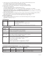
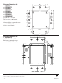
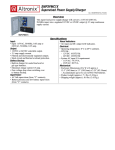
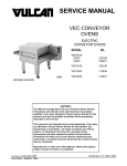
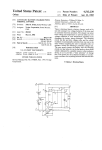
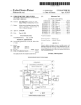
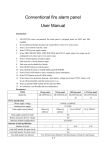
SMP3CTX Series - Installation Guide
Al
tro
M nix
od
el
Nu
m
be
r
Ac
c
Di esso
s r
M tribu y Po
od ti w
u o e
Nu le(s n r
)
m
b
Fu er o
f
se
d O Ou
ut tput
PT
pu
s
C
Ou ts
In
tp
d
u
Ra ivid ts
tin ual
g O
Su (am utp
p) ut
pe
rv
11 ised
In 5VA
pu C
tC /2
ur 30
re VA
12
nt C
/
(a
2
Ou 4V
m
p)
tp D
ut C
T
Cu o
r re tal
nt
(a
m
p)
SMP3CTX Series Power Supply Configuration Reference Chart:
SMP3CTX
-
1
-
-
-
-
.65 / .35 2.5
SMP3PMCTX
-
1
-
-
-
x
.65 / .35 2.5
SMP3PMCTXX
-
1
-
-
-
x
.65 / .35 2.5
PD4
4
x
-
3.5
x
.65 / .35 2.5
PD4CB
4
-
x
2.5
x
.65 / .35 2.5
PD8
8
x
-
3.5
x
.65 / .35 2.5
SMP3PMP8CB
PD8CB
8
-
x
2.5
x
.65 / .35 2.5
SMP3PMP16
PD16W
16
x
-
3.5
x
.65 / .35 2.5
PD16WCB 16
-
x
2.5
x
.65 / .35 2.5
SMP3PMP4
SMP3PMP4CB
SMP3PMP8
SMP3PMP16CB
Overview:
These units will convert a 115VAC or 230VAC, 50/60Hz input, into a regulated 12VDC or 24VDC output up 2.5 amp of
continuous load current (see specifications).
Specifications:
•
•
•
•
•
Universal 115/230VAC input.
Maximum charge current .5 amp.
Filtered and electronically regulated outputs.
Built-in charger for sealed lead acid or gel type batteries.
Automatic switch over to stand-by battery when
AC fails (zero voltage drop).
• AC input and DC output LED indicators.
• Short circuit and thermal overload protection.
• Complete with power supply, power distribution module
(when applicable), enclosure, cam lock & battery leads.
• Power on-off switch.
Supervised models only:
• AC fail supervision (form "C" contacts).
• Low battery supervision (form "C" contacts).
Power Supply Voltage Output Specifications: *
Output VDC
Switch Position
Max. Load DC
12VDC
SW1 - Closed (Fig. 1b, pg. 3)
2.5 amp
24VDC
SW1 - Open (Fig. 1b, pg. 3)
2.5 amp
*Specified at 25˚ C ambient.
Installation Instructions:
Wiring methods shall be in accordance with the National Electrical Code/NFPA 70/NFPA 72/ANSI, and with all local
codes and authorities having jurisdiction. Product is intended for indoor use only.
1. Mount unit in desired location. Mark and predrill holes in the wall to line up with the top two keyholes in the
enclosure. Install two upper fasteners and screws in the wall with the screw heads protruding. Place the enclosure’s
upper keyholes over the two upper screws, level and secure. Mark the position of the lower two holes. Remove the
enclosure. Drill the lower holes and install the three fasteners. Place the enclosure’s upper keyholes over the two
upper screws. Install the two lower screws and make sure to tighten all screws (Enclosure Dimensions, pg. 4).
Secure enclosure to earth ground.
2. Set SW1 on the power supply board to the desired DC output voltage
(Power Supply Voltage Output Specification Chart).
SMP3CTXseries
-1-
3. Connect AC power to terminals marked [L & N], connect ground to terminal marked [G] (if used).
Use 18 AWG or larger for all power connections (Battery, DC output).
Use 22 AWG to 18 AWG for power limited circuits (AC Fail/Low Battery reporting).
4. Measure output voltage before connecting devices. This helps avoid potential damage.
5. Connect devices to be powered:
a. For Power Supply Board connect to terminals marked [– DC +].
b. For Power Distribution Module(s) connect devices to be powered to terminal pairs 1 to 4 marked
[1P & 1N thru 4P & 4N] (Fig. 2, pg. 3), 1 to 8 marked [1P & 1N thru 8P & 8N] (Fig. 3, pg. 3), or 1 to 16 marked
[1P & 1N thru 16P & 16N] (Fig. 4, pg. 3) carefully observing correct polarity.
*Note: Power switch is used to disconnect the L (HOT) terminal from the rest of the board. When servicing the unit,
AC mains should be removed.
6. When using stand-by batteries, they must be lead acid or gel type. Connect battery to terminals marked [– BAT +]
(battery leads included). Use two (2) 12VDC batteries connected in series for 24VDC operation.
Note: When batteries are not used a loss of AC will result in the loss of output voltage.
For supervised models only:
7. Connect appropriate signaling notification devices to AC Fail & Low Bat supervisory relay outputs
marked [NC, C, NO] (Fig. 1a, pg. 3).
LED Diagnostics:
Red (DC)
Green (AC)
Power Supply Status
ON
ON
OFF
OFF
ON
OFF
ON
OFF
Normal operating condition.
Loss of AC, Stand-by battery supplying power.
No DC output.
Loss of AC. Discharged or no stand-by battery. No DC output.
Terminal Identification:
Terminal
Legend
Function/Description
L, G, N
Connect 115VAC/230VAC to these terminals:
L to Hot, N to Neutral, G to ground (if used).
– DC +
12VDC / 24VDC @ 2.5 amp continuous non-power limited output.
*AC FAIL
NC, C, NO
Indicates loss of AC power, e.g. connect to audible device or alarm
panel. Relay normally energized when AC power is present.
Contact rating 1 amp @ 120VAC / 28VDC.
*Low Battery
NC, C, NO
Indicates low battery condition, e.g. connect to alarm panel.
Relay normally energized when DC power is present.
Contact rating 1 amp @ 120VAC / 28VDC
Low battery threshold:
12VDC output threshold set @ approximately 10.5VDC,
24VDC output threshold set @ approximately 21VDC.
– BAT +
Stand-by battery connections. Maximum charge rate .5 amp.
*Note: Supervised models only
PD4/PD4CB/PD8/PD8CB/PD16W/PD16WCB - Power Distribution Module
PD4/PD4CB
1P to 4P
1N to 4N
-2-
Terminal Legend
PD8/PD8CB
PD16W/PD16WCB
1P to 8P
1P to16P
1N to 8N
1N to 16N
Function/
Description
Positive DC power outputs.
Negative DC power outputs.
SMP3CTXseries
Fig. 1
CAUTION: De-energize unit prior to servicing.
OFF
ON
5A 250V
L
N
Green
Lead
Power Supply
Board
AC FAIL
NC
115/230VAC
power
mains
Power
Distribution
Module(s)
NC C
NO
LOW BAT
C NO
NO
NC
NC C
AC FAIL
C NO
Fig. 1a
INPUT
G
Wire
Strap
(from
Enclosure
to Door)
LOW BAT
--- DC +
OPEN - 24VDC
CLOSED - 12VDC
--- BAT +
Fig. 1b
OPEN - 24VDC
CLOSED - 12VDC
12VDC Rechargeable Battery
(optional)
12VDC Rechargeable Battery
(optional)
CAUTION: When power supply board is set for 12VDC use only one (1) 12VDC
stand-by battery.
Power Distribution Module(s):
Fig. 2
F1
F1
Used on
PTC Models
F2
F3
F4
Fig. 4
1P, 2P,3P,4P = FUSED OUTPUT
S
1N, 2N, 3N, 4N = OMMON
C
OUTPUT
S
1 2 3 4 5 6 7 8
LED
2N
3P
3N
4P
4N
INPUT
P
O U T P UST
N
2P
P OW E R
N
DC Output to devices
From Power Supply
Board
(Factory Installed)
N
1N
9 10 11 12 13 14 15 16
P
P
1P
C O MM O N
common
outputs
protected
outputs
XFMR Input
S
Used on
PTC Models
Fig. 3
OFF
SW1
1
2
3
4
5
6
7
8
ON
1
P
D1
FUSED
POWER
OUTPUTS
R1
LED
3.5A 250V
N
INPUT
COMMON
POWER
OUTPUTS
DC Output to devices
SMP3CTXseries
For continuous protection against risk of fire
replace fuses with same type and rating.
From Power Supply
Board
(Factory Installed)
-3-
Enclosure Dimensions for:
• SMP3CTX
• SMP3PMCTX
• SMP3PMP4
• SMP3PMP4CB
• SMP3PMP8
• SMP3PMP8CB
• SMP3PMP16
• SMP3PMP16CB
1.40"
4.85"
4.85"
1.40"
1.20"
3.25"
Top
12.50"
1.20"
0.75"
1.20"
11.00"
0.75"
0.9375"
1.40"
1.40"
5.10"
5.10"
13.5”H x 13”W x 3.25”D
Enclosure accommodates up to
two (2) 12VDC/7AH batteries.
Left
Also available to accommodate up to
two (2) 12VDC/12AH batteries
(please contact Altronix).
Right
5.10"
6.5625"
0.9375"
3.25"
3.25"
Bottom
3.25"
1.00"
1.00"
1.00"
Enclosure Dimensions for:
• SMP3PMCTXX
1.500"
10.50"
4.615"
4.615"
1.00"
1.500"
1.750"
15.5”H x 12.23”W x 4.5”D
Enclosure accommodates up to
two (2) 12VDC/12AH batteries.
1.375"
1.125"
4.500"
12.230"
1.250"
4.500"
1.100"
1.250"
1.100"
0.910"
0.910"
1.500"
1.500"
2.000"
15.500"
2.000"
5.000"
5.000"
0.790"
1.250"
1.100"
1.250"
1.750"
1.500"
4.615"
4.615"
1.500"
Altronix is not responsible for any typographical errors. Product specifications are subject to change without notice.
Altronix Corp.
140 58th Street, Brooklyn, New York 11220 USA, 718-567-8181, fax: 718-567-9056
web site: www.altronix.com, e-mail: [email protected], Made in U.S.A.
H02J
IISMP3CTX series - Rev. 051105
-4-
MEMBER
SMP3CTXseries