1
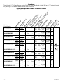
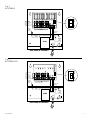
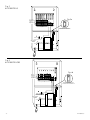
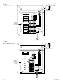
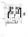
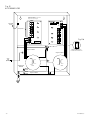
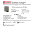
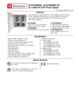
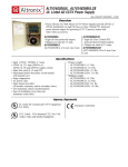
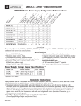
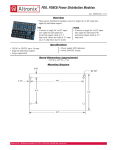
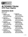
ALTV248UL3 Series CCTV Power Supplies Installation Guide Models Include: • ALTV248UL3 • ALTV248ULCB3 • ALTV248175UL3 • ALTV248175ULCB3 • ALTV248300UL3 • ALTV248300ULCB3 • ALTV248300ULM3 • ALTV248300ULCBM3 • ALTV248600UL3 • ALTV248600ULCB3 - - - - - - - - - - - - - - - 24VAC @ 3.5 amp (85VA) - or 28VAC @ 3 amp (85VA). Eight (8) Fuse Protected Outputs. - Factory installed 3-wire linecord. - 24VAC @ 7 amp (175VA) - or 28VAC @ 6.25 amp (175VA). Eight (8) Fuse Protected Outputs. - Factory installed 3-wire linecord. - 24VAC @ 12.5 amp (300VA) - or 28VAC @ 10 amp (280VA). Eight (8) Fuse Protected Outputs. - Factory installed 3-wire linecord. - 24VAC @ 12.5 amp (300VA) - or 28VAC @ 10 amp (280VA). Eight (8) Fuse Protected Outputs. - Factory installed 3-wire linecord. - 24VAC @ 25 amp (600VA) - or 28VAC @ 20 amp (560VA). Eight (8) Fuse Protected Outputs. - Factory installed 3-wire linecord. - 24VAC @ 3.5 amp (85VA) or 28VAC @ 3 amp (85VA). Eight (8) PTC Protected Outputs. Factory installed 3-wire linecord. 24VAC @ 7 amp (175VA) or 28VAC @ 6.25 amp (175VA). Eight (8) PTC Protected Outputs. Factory installed 3-wire linecord. 24VAC @ 12.5 amp (300VA) or 28VAC @ 10 amp (280VA). Eight (8) PTC Protected Outputs. Factory installed 3-wire linecord. 24VAC @ 12.5 amp (300VA) or 28VAC @ 10 amp (280VA). Eight (8) PTC Protected Outputs. Factory installed 3-wire linecord. 24VAC @ 25 amp (600VA) or 28VAC @ 20 amp (560VA) Eight (8) PTC Protected Outputs. Factory installed 3-wire linecord. Rev. 040506 Overview: These Altronix CCTV Power Supplies provide 24VAC or 28VAC distributed via eight (8) fuse or PTC protected outputs for powering CCTV Cameras, heaters and other video accessories. ALTV248UL3 ALTV248ULCB3 ALTV248175UL3 ALTV248175ULCB3 ALTV248300UL3 ALTV248300ULCB3 ALTV248300ULM3 ALTV248300ULCBM3 ALTV248600UL3 ALTV248600ULCB3 - 2 - To t tp Ou Altronix Model Number ut Vo lta ge al (P Out ow pu er) t C ur Nu ren m t be PT r o f C po Pro Outp w u (C er l tecte ts las im d s 3 ite Ou Fu fo d fo tpu se r W r ts Pr et Dry (Cla ot e cte loc loc ss In di d C atio ati 2 vi ns on d las no ua s 1 ). s). tt lO Fu o e ut Ou xc pu se tp e t ut Ra ed C s ur tin t o r M e g t a n s lo t( ain ut m Fu pu ax se t c pe Ra ur r ren ou t in Pr g t ) t pu im s t a r Fu y I se nRa lin tin e 11 gs 5V A In C p 5 Ag ut C 0/6 u 0H e Li ncy rren z sti t ng s Eight (8) Output ALTV248UL Reference Chart: 24VAC 3.5 amp 28VAC 3 amp 24VAC 3.5 amp 28VAC 3 amp 24VAC 7 amp 28VAC 6.25 amp 24VAC 7 amp 28VAC 6.25 amp 24VAC 12.5 amp 28VAC 10 amp 24VAC 12.5 amp 28VAC 10 amp 24VAC 12.5 amp 28VAC 10 amp 24VAC 12.5 amp 28VAC 10 amp 24VAC 25 amp 28VAC 20 amp 24VAC 25 amp 28VAC 20 amp 8 --- Yes 3.5 amp 3.5 amp 5 amp/ 3.5 amp/ .9 250V 250V amp 8 Yes --- 2.5 amp --- 5 amp/ 3.5 amp/ .9 250V 250V amp 8 --- Yes 3.5 amp 8 Yes --- 2.5 amp 8 --- Yes 3.5 amp 3.5 15 amp/ amp 32V 3.5 10 amp/ 3.5 amp/ 1.76 amp 250V 250V amp --- 10 amp/ 3.5 amp/ 1.76 250V 250V amp --- 2.7 amp 15 amp/ 32V --- 2.7 amp 3.5 15 amp/ amp 32V --- 2.7 amp 15 amp/ 32V --- 2.7 amp 3.5 15 amp/ amp 32V --- 5.4 amp 15 amp/ 32V --- 5.4 amp 8 Yes --- 2.5 amp 8 --- Yes 3.5 amp 8 Yes --- 2.5 amp 8 --- Yes 3.5 amp 8 Yes --- 2.5 amp --- --- --- ALTV248UL3series Specification: • UL Listed for Commercial CCTV Equipment (UL 2044). Enclosure Dimensions: CUL Listed - CSA Standard C22.2 No.1-98, Audio, Video and Similar Equipment. •Surge suppression. •AC power LED indicator. •Power ON/OFF switch (ALTV248UL3, ALTV248ULCB3). •Illuminated power disconnect circuit breaker with manual reset (all other models). •Unit maintains camera synchronization. •Ease of installation saves time & eliminates costly labor. •Spare fuses included (on fuse protected models). •Factory installed 3-wire line cord. ALTV248UL3 and ALTV248ULCB3: 8.5”H x 7.5”W x 3.5”D ALTV248300ULM3, and ALTV248300ULCBM3: 8.5”H x 7.5”W x 3.75”D ALTV248175UL3, ALTV248175ULCB3, ALTV248300UL3 and ALTV248300ULCB3: 12”H x 7.75”W x 4.5”D ALTV248600UL3 and ALTV248600ULCB3: 13.5”H x 13”W x 3.25”D Installation Instructions: Wiring methods shall be in accordance with the National Electrical Code/NFPA 70/NFPA 72/ANSI, and with all local codes and authorities having jurisdiction. Product is intended for indoor use only. 1. Mount unit in desired location. Mark and predrill holes in the wall to line up with the top two keyholes in the enclosure. Install two upper fasteners and screws in the wall with the screw heads protruding. Place the enclosure’s upper keyholes over the two upper screws, level and secure. Mark the position of the lower two holes. Remove the enclosure. Drill the lower holes and install the three fasteners. Place the enclosure’s upper keyholes over the two upper screws. Install the two lower screws and make sure to tighten all screws (Enclosure Dimensions, pg. 11, 12). Secure enclosure to earth ground. 2. Set power switch on power distribution board marked [PD] to OFF position for models ALTV248UL3 or ALTV248ULCB3 (Figs. 1a, 2a, pg. 5). Set power disconnect circuit breaker to OFF position for all other models (Figs. 3a-10a, pgs. 6-10). 3. All units are factory set for 24VAC operation. For 28VAC operation adjust unit prior to mounting and applying power as follows: Change the wire position so that the wire marked [28V] is connected to the terminal marked [P] and the wire marked [24V] is connected to the terminal marked [S]. Note: ALTV248ULCB3 set for 28VAC operation is not Class 2 Rated, not power limited. 4. Connect AC power to the black and white flying leads of the transformer(s) (Figs. 1-10, pgs. 5-10), secure green lead to earth ground. Use 18 AWG or larger for all power connections. Keep power limited (PTC protected outputs only) wiring separate from non-power limited wiring. Minimum .25” spacing must be provided. Use separate knockouts. 5. Set power switch on power distribution board marked [PD] to ON position for models ALTV248UL3 or ALTV248ULCB3 (Figs. 1a, 2a, pg. 5). Set power disconnect circuit breaker to RESET (ON) position for all other models (Figs. 3a-10a, pgs. 6-10). 6. Measure output voltage before connecting devices. This helps avoid potential damage. Terminals marked [1P - 8P] are of the same polarity. CAUTION: Determine the maximum operating voltage of the equipment being powered before adjusting the output voltage. 7. Set power switch on power distribution board marked [PD] to OFF position for models ALTV248UL3 or ALTV248ULCB3 (Figs. 1a, 2a, pg. 5). Set power disconnect circuit breaker to OFF position for all other models (Figs. 3a-10a, pgs. 6-10). 8. Connect devices to terminals marked [1P - 1N through 4P - 4N] on PD4/PD4CB board (Figs. 9, 10, pgs. 9, 10) or terminals marked [1P - 1N through 8P - 8N] on PD8/PD8CB board (Figs. 1-8, pgs. 5-8), carefully observing polarity. 9. Set power switch on power distribution board marked [PD] to ON position for models ALTV248UL3 or ALTV248ULCB3 (Figs. 1a, 2a, pg. 5). Set power disconnect circuit breaker to RESET (ON) position for all other models (Figs. 3a-10a, pgs. 6-10). 10.Green LED will illuminate when power is present. 11.Upon completion of wiring, secure enclosure door with screws (supplied). Installation of cam lock is optional. Caution: Equipment to be installed/serviced by authorized/trained personnel only. Shut branch circuit power before installing/servicing equipment. ALTV248UL3series -3- WARNING: To reduce the risk of fire or electric shock, do not expose the unit to rain or moisture. This installation should be made by qualified service personnel and should conform to all local codes and in accordance with the National Electrical Code. Use 75º C or higher rated UL insulated wiring for connecting the unit to the mains. Replace fuses with the same type and rating (refer to Eight (8) Output ALTV248UL3 Reference Chart, pg. 2). Terminal Identification: PD4 - Power Distribution Module Terminal Legend Function/Description 1P - 4P AC output 1N - 4N AC output PD8 - Power Distribution Module Terminal Legend Function/Description 1P - 8P AC output 1N - 8N AC output The lightning flash with arrow head symbol within an equilateral triangle is intended to alert the user to the presence of an insulated “DANGEROUS VOLTAGE” within the products enclosure that may be of sufficient magnitude to constitute an electric shock. The exclamation point within an equilateral triangle is intended to alert the user to the presence of important operating and maintenance (servicing) instructions in the literature accompanying the appliance. CAUTION: To reduce the risk of electric shock do not open enclosure. There are no user serviceable parts inside. Refer servicing to qualified service personnel. - 4 - ALTV248UL3series OFF OFF MAIN FUSE Fig. 1 ALTV248UL3 ON 24VAC or 28VAC output 1 (Follow same procedure using terminals 2P & N through 8P & N outputs 2 through 8) POWER OUTPUTS ON FUSED COMMON POWER Primary In-line Fuse N OUTPUTS P S Class 1 Outputs non-power limited non-power limited Black Lead Black Lead 115VAC Input 50/60 Hz. XFMR White Lead Green Lead (Ground) Back Panel of Enclosure F3 F4 F5 F6 F7 F8 OFF F2 OFF F1 MAIN FUSE Fig. 2 ALTV248ULCB3 P D1 POWER LED R1 OUTPUTS N ON FUSED INPUT COMMON Primary In-line Fuse ON 24VAC or 28VAC output 1 (Follow same procedure using terminals 2P & N through 8P & N outputs 2 through 8) POWER OUTPUTS N P S 24VAC configuration Class 2 Not Wet/Class 3 Wet 28VAC configuration Class 1 non-power limited non-power limited Black Lead Black Lead 115VAC Input 50/60 Hz. XFMR White Lead Green Lead (Ground) Back Panel of Enclosure ALTV248UL3series -5- MAIN FUSE Fig. 3 ALTV248175UL3 24VAC or 28VAC output 1 (Follow same procedure using terminals 2P & N through 8P & N outputs 2 through 8) FUSED POWER COMMON POWER Fig. 3a OUTPUTS N OUTPUTS P S non-power limited Class 1 Outputs Illuminated Power Disconnect Circuit Breaker with manual reset Black Lead 115VAC input 50/60 Hz White Lead XFMR Green Lead (ground) F1 F2 F3 F4 F5 F6 F7 MAIN FUSE Fig. 4 ALTV248175ULCB3 F8 Fig. 4a 24VAC or 28VAC output 1 (Follow same procedure using terminals 2P & N through 8P & N outputs 2 through 8) P D1 FUSED POWER LED R1 OUTPUTS N INPUT COMMON POWER N OUTPUTS 24VAC configuration Class 2 Not Wet/Class 3 Wet P S non-power limited Illuminated Power Disconnect Circuit Breaker with manual reset Black Lead 115VAC input 50/60 Hz White Lead XFMR Green Lead (ground) - 6 - ALTV248UL3series MAIN FUSE Fig. 5 ALTV248300UL3 24VAC or 28VAC output 1 (Follow same procedure using terminals 2P & N through 8P & N outputs 2 through 8) P Fig. 5a D1 FUSED POWER N LED R1 OUTPUTS INPUT COMMON POWER OUTPUTS N P S non-power limited Class 1 Outputs Illuminated Power Disconnect Circuit Breaker with manual reset 115VAC input 50/60 Hz White Lead XFMR* Green Lead (ground) Fig. 6 ALTV248300ULCB3 24VAC or 28VAC output 1 (Follow same procedure using terminals 2P & N through 8P & N outputs 2 through 8) Fig. 6a 24VAC configuration Class 2 Not Wet/Class 3 Wet non-power limited Illuminated Power Disconnect Circuit Breaker with manual reset 115VAC input 50/60 Hz White Lead XFMR* ALTV248UL3series Green Lead (ground) -7- Fig. 7 ALTV248300ULM3 Fig. 7a INPUT Illuminated Power Disconnect Circuit Breaker with manual reset COMMON POWER POWER OUTPUTS 7 6 5 4 FUSED 3 Black Lead 115VAC Input, 50/60 Hz. White Lead P N 1 2 XFMR* OUTPUTS 8 N D1 R1 P S LED MAIN FUSE Transformer underneath power supply board Fig. 8 ALTV248300ULCBM3 Fig. 8a LED MAIN FUSE D1 OUTPUTS COMMON Black Lead 115VAC Input, 50/60 Hz. White Lead N P F1 FUSED F2 XFMR* - 8 - POWER OUTPUTS POWER F4 F3 Transformer underneath power supply board F5 F6 N F7 R1 P F8 S INPUT Illuminated Power Disconnect Circuit Breaker with manual reset ALTV248UL3series Fig. 9 ALTV248600UL3 MAIN FUSE N P S Connected to Door INPUT 24VAC or 28VAC fused ( Follow same procedure using terminals 2P & N thru 4P & N outputs 2 thru 4). Class 1 outputs N P Fig. 9a S INPUT MAIN FUSE non-power limited Illuminated Power Disconnect Circuit Breaker with manual reset non-power limited Green Lead (Ground) 115VAC input, 50/60 Hz. XFMR* XFMR* Black Lead White Lead ALTV248UL3series non-power limited -9- Fig. 10 ALTV248600ULCB3 INPUT 24VAC or 28VAC output 1 (Follow same procedure using terminals 2P & N through 4P & N outputs 2 through 4) N P S Connected to Door 24VAC configuration Class 2 Not Wet/Class 3 Wet N P Fig. 10a S INPUT non-power limited Illuminated Power Disconnect Circuit Breaker with manual reset non-power limited Green Lead (Ground) 115VAC input, 50/60 Hz. XFMR* XFMR* Black Lead White Lead - 10 - non-power limited ALTV248UL3series Enclosure Dimensions for: • ALTV248UL3 • ALTV248ULCB3 8.5”H x 7.5”W x 3.5”D Enclosure Dimensions for: • ALTV248300ULM3 • ALTV248300ULCBM3 8.5”H x 7.5”W x 3.75”D 3.63" 1.25" 3.85" 7.25" 1.25" 0.60" 0.60" 1.25" 0.90" 1.00" 0.90" 8.13" 1.00" 8.13" 8.13" 1.75" 1.00" 1.00" 1.25" 0.60" 0.60" 3.85" 7.25" 3.85" 1.00" 1.00" 1.00" 7.25" ALTV248UL3series - 11 - Enclosure Dimensions for: • ALTV248175UL3 • ALTV248175ULCB3 • ALTV248300UL3 • ALTV248300ULCB3 7.50" 4.50" 12”H x 7.25”W x 4.5”D 1.25" 0.50" 0.50" 1.11" 1.50" 1.25" 1.11" 1.50" 3.50" 12" 3.50" 12" 2.50" 12" 5.88" 3.50" 1.13" 1.00" 4.50" 7.50" 4.50" 4.50" 1.00" 1.00" 0.88" 5.75" 0.88" 7.50" Enclosure Dimensions for: • ALTV248600UL3 • ALTV248600ULCB3 13.5”H x 13”W x 3.25”D Altronix is not responsible for any typographical errors. Altronix Corp. 140 58th Street, Brooklyn, New York 11220 USA, 718-567-8181, fax: 718-567-9056 web site: www.altronix.com, e-mail: [email protected], Lifetime Warranty, Made in U.S.A. II1ALTV248UL3Series H04I - 12 - MEMBER ALTV248UL3series