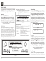
1
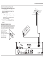
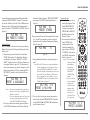
McIntosh Laboratory, Inc. 2 Chambers Street Binghamton, New York MR87 AM/FM Tuner Owner’s Manual 13903-2699 Phone: 607-723-3512 www.mcintoshlabs.com The lightning flash with arrowhead, within an equilateral triangle, is intended to alert the user to the presence of uninsulated “dangerous voltage” within the product’s enclosure that may be of sufficient magnitude to constitute a risk of electric shock to persons. WARNING - TO REDUCE RISK OF FIRE OR ELECTRICAL SHOCK, DO NOT EXPOSE THIS EQUIPMENT TO RAIN OR MOISTURE. IMPORTANT SAFETY INSTRUCTIONS! PLEASE READ THEM BEFORE OPERATING THIS EQUIPMENT. 1. Read these instructions. 2. Keep these instructions. 3. Heed all warnings. 4. Follow all instructions. 5. Do not use this apparatus near water. 6. Clean only with a dry cloth. 7. Do not block any ventilation openings. Install in accordance with the manufacturer’s instructions. 8. Do not install near any heat sources such as radiators, heat registers, stoves, or other apparatus (including amplifiers) that produce heat. 9. Do not defeat the safety purpose of the polarized or grounding-type plug. A polarized plug has two blades with one wider than the other. A grounding type plug has two blades and a 2 The exclamation point within an equilateral triangle is intended to alert the user to the presence of important operating and maintenance (servicing) instructions in the literature accompanying the appliance. NO USER-SERVICEABLE PARTS INSIDE. REFER SERVICING TO QUALIFIED PERSONNEL. third grounding prong. The wide blade or the third prong are provided for your safety. If the provided plug does not fit into your outlet, consult an electrician for replacement of the obsolete outlet. 10. Protect the power cord from being walked on or pinched particularly at plugs, convenience receptacles, and the point where they exit from the apparatus. 11. Only use attachments/accessories specified by the manufacturer. 12. Use only with the cart, stand, tripod, bracket, or table specified by the manufacturer, or sold with the apparatus. When a cart is used, use caution when moving the cart/ apparatus combination to avoid injury from tip-over. 13. Unplug this apparatus during lightning storms or when unused for long periods of time. 14. Refer all servicing to qualified service personnel. Servicing is required when the apparatus has been damaged in any way, such as power- To prevent the risk of electric shock, do not remove cover or back. No user-serviceable parts inside. supply cord or plug is damaged, liquid has been spilled or objects have fallen into the apparatus, the apparatus has been exposed to rain or moisture, does not operate normally, or has been dropped. 15. Do not expose this equipment to dripping or splashing and ensure that no objects filled with liquids, such as vases, are placed on the equipment. 16. To completely disconnect this equipment from the a.c. mains, disconnect the power supply cord plug from the a.c. receptacle. 17. The mains plug of the power supply cord shall remain readily operable. 18. Do not expose batteries to excessive heat such as sunshine, fire or the like. 19. Connect mains power supply cord only to a mains socket outlet with a protective earthing connection. Outdoor Antenna Grounding If an outside antenna or cable system is connected to the product, be sure the antenna or cable system is grounded so as to provide some protection against voltage surges and built-up static charge. Article 810 of the National Electrical Code, ANSI/ NFPA 70, provides information with reguards to proper grounding of the mast and supporting structure, grounding of the lead-in wire to an antenna discharge unit, and size of ground conductors, location of antenna-discharge unit, connection to ground electrodes and requirements for the grounding electrode. Example of antenna grounding as per National Electrical Code, ANSI/NFPA 70 Table of Contents Thank You Safety Instructions................................................... 2-3 Table of Contents........................................................ 3 Thank You and Please Take a Moment....................... 3 Technical Assistance................................................... 3 Customer Service and General Information............... 4 Connector and Cable Information.............................. 4 Introduction................................................................. 5 Performance Features................................................. 5 Dimensions................................................................. 6 Installation.................................................................. 7 Your decision to own this McIntosh MR87 AM/FM Tuner ranks you at the very top among discriminating music listeners. You now have “The Best.” The McIntosh dedication to “Quality,” is assurance that you will receive many years of musical enjoyment from this unit. Please take a short time to read the information in this manual. We want you to be as familiar as possible with all the features and functions of your new McIntosh. Connections: Rear Panel and RAA2 Connections........................... 8 How to Connect Antennas.......................................... 9 How to Connect the MR87.................................. 10-11 Please Take A Moment Remote Control: Remote Control Push-buttons................................... 12 How to use the Remote Control................................ 13 Front Panel and Setup: Front Panel Displays, Controls and Push-buttons..... 14 Setup.................................................................... 15-19 Operation: How to Operate the MR87...................................20-23 Additional Information: Photos...................................................................24-25 Specifications............................................................ 26 Packing Instruction................................................... 27 Copyright 2009 © by McIntosh Laboratory, Inc. The serial number, purchase date and McIntosh Dealer name are important to you for possible insurance claim or future service. The spaces below have been provided for you to record that information: Serial Number:________________________________ Purchase Date:_ _______________________________ Dealer Name:_ ________________________________ Technical Assistance If at any time you have questions about your McIntosh product, contact your McIntosh Dealer who is familiar with your McIntosh equipment and any other brands that may be part of your system. If you or your Dealer wish additional help concerning a suspected problem, you can receive technical assistance for all McIntosh products at: McIntosh Laboratory, Inc. 2 Chambers Street Binghamton, New York 13903 Phone: 607-723-3512 Fax: 607-724-0549 3 Customer Service If it is determined that your McIntosh product is in need of repair, you can return it to your Dealer. You can also return it to the McIntosh Laboratory Service Department. For assistance on factory repair return procedure, contact the McIntosh Service Department at: McIntosh Laboratory, Inc. 2 Chambers Street Binghamton, New York 13903 Phone: 607-723-3515 Fax: 607-723-1917 General Information 1. For additional connection information, refer to the owner’s manual(s) for any component(s) connected to the MR87 AM/FM Tuner. 2. The Main AC Power going to the MR87 and any other McIntosh Component(s) should not be applied until all the system components are connected together. Failure to do so could result in malfunctioning of some or all of the system’s normal operations. When the MR87 and other McIntosh Components are in their Standby Power Off Mode, the Microprocessor’s Circuitry inside each component is active and communication is occurring between them. 3. The Balanced and Unbalanced Outputs may be used simultaneously. 4. The Remote Control Supplied with the MR87 Tuner is capable of operating other components. For additional information go to www.mcintoshlabs. com. 5. When discarding the unit, comply with local rules or regulations. Batteries should never be thrown away or incinerated but disposed of in accordance 4 with the local regulations concerning battery disposal. 7. For additional information on the MR87 and other McIntosh Products please visit the McIntosh Web Site at www.mcintoshlabs.com. Connector and Cable Information XLR Connectors Below is the Pin configuration for the XLR Balanced Output Connectors on the MR87. Refer to the diagrams for connections: PIN 1: Shield/Ground PIN 2: + Signal PIN 1 PIN 3: - Signal PIN 2 PIN 3 Power Control Connectors The MR87 Power Control Input/Output Jacks receive/ send Power On/Off Signals when connected to other McIntosh Components. A 1/8 Power inch stereo mini phone plug Control is used for connection to the N/C Power Control Input/Output on the MR87. Ground Note: The Data and Power Control Connecting Cable is available from the McIntosh Parts Department: Data and Power Control Cable Part No. 170-202 Six foot, shielded 2 conductor, with 1/8 inch stereo mini phone plugs on each end. Data and IR Input Port Connectors The MR87 Data In Port receives Remote Control Signals. A 1/8 Data Signal inch stereo mini phone plug is N/C used for connection. The IR Port Data also use a 1/8 inch stereo mini Ground phone plug and allow the connection of other brand IR Receivers IR Data to the MR87. Control N/C Ground RAA2 Connectors Pin No. 1. 2. 3. 4. 5. 6. 7. 8. Wire Color White/Orange Orange Pin 8 White/Green Blue White/Blue Pin 1 Green White/Brown Brown *Cable outer shield Pin 1 *Cable outer shield Pin 8 Note: The RAA2 Connecting Cable is available from the McIntosh Parts Department: RAA2 Antenna Cable Part No. 171844 Twenty foot, shielded 8 conductor, with a shielded RJ45 connector on each end. General Information, Cable Information, Introduction and Performance Features Introduction The MR87 AM/FM Tuner is an elegant instrument for superb reception from Radio Stations. The MR87 uses the latest in technology for the best sound quality, along with the convenient operation of a Dial Glass with Tuning Pointer used in classic McIntosh Analog Tuners. Performance Features • Digital Audio Outputs There are Coaxial and Optical Digital Outputs for external decoding of the PCM Signal. • Multifunction Fluorescent Display The Front Panel Display indicates various setup and tuner functions. • Special FM RF Circuitry The MR87 RF Circuitry receives strong local FM Station Signals without distortion and receives even the weakest of FM Signals with low noise. • Information Service The MR87 will indicate various text information such as Station Call Sign, Music Genre, Artist Name and Song Title when transmitted by the Radio Station. • RAA2 External AM Antenna The RAA2 External AM Antenna allows placement of the AM Antenna for the best reception. • Remote Control with External Sensor Input The Remote Control provides control of the MR87 operating functions and other McIntosh Source Components. Enjoy your McIntosh System from other rooms in your home by connecting external sensors. • Preset Stations and Permanent Memory The MR87 Tuner stores up to twenty AM and FM Station presets and they are retained in Permanent Memory. • Flywheel Tuning and Electronic Dial Pointer The Smooth Acting Weighted Tuning mechanism with Glass Dial and Illuminated Electronic Pointer recall the classic McIntosh tuner designs of the 60’s and 70’s while a full complement of RS232 control with metadata support makes the MR87 the go-to multiformat broadcast audio source for today’s whole-house systems. • Balanced Outputs The Balanced Outputs allow connection of the MR87 to a Preamplifier using long cable lengths without a loss in sound quality. • Fiber Optic Solid State Front Panel Illumination The even Illumination of the Front Panel is accomplished by the combination of custom designed Fiber Optic Light Diffusers and extra long life Light Emitting Diodes (LEDs). •Glass Front Panel and Super Mirror Chassis Finish The famous McIntosh Illuminated Glass Front Panel and the Stainless Steel Chassis with Super Mirror Finish ensures the pristine beauty of the MR87 will be retained for many years. • Power Control Output and Trigger Assignment A Power Control connection for convenient Turn-On of McIntosh Power Components and Accessories is included. • Special Power Supply Fully regulated Power Supplies and a special R-Core Power Transformer ensure stable noise free operation even though the power line varies. • Gold Plated Connectors The MR87 Digital and Analog Audio Connectors are gold plated for superior corrosion resistance and high electrical conductivity. 5 Dimensions Dimensions The following dimensions can assist in determining the best location for your MR87. Front View of the MR87 17-1/2" 44.45cm P1 91.5 MHz ST ¦ Pink Floyd: Money 5-3/8" 13.69cm 6" 15.24cm Side View of the MR87 15-7/8" 40.32cm 5/8" 1.59cm 14-1/2" 36.83cm 3/16" 0.48cm Rear View of the MR87 17" 13/16" 2.06cm 43.18cm 2" 4-5/8" 11.75cm 13-1/4" 33.65cm 6 5.08cm 10-9/16" 26.83cm 1-15/16" 4.92cm 4-13/16" 12.22cm Installation Installation The MR87 can be placed upright on a table or shelf, standing on its four feet. It also can be custom installed in a piece of furniture or cabinet of your choice. The four feet may be removed from the bottom of the MR87 when it is custom installed as outlined below. The four feet together with the mounting screws should be retained for possible future use if the MR87 is removed from the custom installation and used free standing. The required panel cutout, ventilation cutout and unit dimensions are shown. Always provide adequate ventilation for your MR87. Cool operation ensures the longest possible operating life for any electronic instrument. Do not install the MR87 directly above a heat generating component such as a high powered amplifier. If all the components are installed in a single cabinet, a quiet running ventilation fan can be a definite asset in maintaining all the system components at the coolest possible operating temperature. When the MR87 is placed free-standing on a flat surface, allow at least 2 inches (5.08cm) above the top, 2 inches (5.08cm) below the bottom and 2 inches (5.08cm) on each side of the Tuner, so airflow is not obstructed. Allow 19-1/2 inches (49.53cm) depth behind the front panel. Allow 1-7/16 inch (3.66cm) in front of the mounting panel for knob clearance. A custom cabinet installation should provide the minimum spacing dimensions for cool operation. Allow at least 2 inches (5.08cm) above the top, 2 inches (5.08cm) below the bottom and 2 inches (5.08cm) on each side of the Tuner, so airflow is not obstructed. The Custom Cabinet should be open backed and at least 12 inches (30.48cm) away from any surface such as a wall. Be sure to cut out a ventilation hole in the mounting shelf according to the dimensions in the drawing. Allow 1-7/16 inch (3.66cm) in front of the mounting panel for knob clearance. 17-1/16" 43.34cm MR87 Front Panel Custom Cabinet Cutout 4-7/8" 12.38cm P1 91.5 MHz ST ¦ Pink Floyd: Money Cabinet Front Panel Cutout Opening for Custom Mounting Cabinet Front Panel 2" 5.08cm MR87 Side View in Custom Cabinet Custom Cabinet has an open back and at least 12” (30.48cm) away from any surface such as a wall Cutout Opening for Ventilation Support Shelf 1" MR87 Bottom View in Custom Cabinet 2.54cm Chassis Spacers 1-1/8" 2.86cm 11" 27.94cm 15" 38.1cm 15" 38.1cm Cutout Opening for Ventilation 1-3/4" 4.45cm Note: Center the cutout Horizontally on the unit. For purposes of clarity, the above illustration is not drawn to scale. 12-5/16" 31.27cm 7 Rear Panel and RAA2 Connections RS232 connector for communications with an external control device POWER CONTROL IN receives signals from a McIntosh component (5-15 Volts ON, 0 Volts OFF). POWER CONTROL OUT sends out (12 Volts ON) signal to another McIntosh Component when the MR87 is On. Used for upgrading the MR87 Firmware IR INput for connecting an IR Receiver COAXIAL AND OPTICAL DIGITAL AUDIO OUTPUTS send signals to a Preamplifier or Control Center with a D/A Converter or a decoder Connect the MR87 power cord to a live AC outlet. Refer to information on the back panel of your MR87 to determine the correct voltage for your unit 8 DATA IN receives operating data from a McIntosh Preamplifier or Control Center Connect to the RAA2 AM ANT connector on MR87 using the supplied cable AM ANT (Antenna) connector allows a McIntosh RAA2 Remote Antenna to be connected BALANCED AUDIO OUTPUTS supply analog audio signals to Balanced Inputs of other components UNBALANCED AUDIO OUTPUTS supply analog audio signals to Unbalanced Inputs of other components 75 OHM FM ANT (Antenna) connects to an external FM Antenna or cable How to Connect Antennas How to Connect Antenna Components 1. Using the supplied shielded cable, connect one end into the RAA2 AM Antenna jack and the other end of the same cable into the MR87 Tuner jack labeled RAA2 AM ANT. FM Antenna Note: If a longer length cable needs to be used between the MR87 and the RAA2 AM Antenna, use an 8 conductor straight-thru cable with an outer shield and RJ45 connectors on each end (shielded CAT5, CAT5e or CAT6 patch cable). 2. Connect a 75 ohm coax cable from a FM Antenna or cable system to the MR87, 75 OHM FM ANT Connector. Mounting the RAA2 AM Antenna Tune to a station with the weakest signal and orient the RAA2 Antenna for maximum signal with minimum noise and distortion. After the location is determined, the RAA2 AM Antenna may be secured to a suitable surface by using two #6 1-3/4 to 2 inches (4.44 to 5.08cm) long screws, refer to the illustration to the right. 9 How to Connect the MR87 The MR87 has the ability to be remotely switched On/ Off from a McIntosh Preamplifier or A/V Control Center via the Power Control connection. The MR87 Data Port Connection allows for the remote operation of basic functions using the Preamplifier or A/V Control Center Remote Control. With an appropriate IR Sensor connected to the MR87, remote control operation is possible from another room and/or when the MR87 is located in a cabinet with the doors closed. The connection instructions below, together with the MR87 Connection Diagram located on the opposite page, is an example of a typical audio or audio/ video system. Your system may vary from this, however the actual components would be connected in a similar manner. For additional information refer to “Connector and Cable Information” on pages 4 and 5. Power Control Connections: 1. Connect a Control Cable from the Preamplifier or A/V Control Center appropriate Jack (Tuner/Trigger 4, Power Control or Trigger) to the POWER CONTROL IN Jack on the McIntosh MR87 Tuner. 2. Optionally, connect a Control Cable from the MR87 Tuner POWER CONTROL OUT jack to the next McIntosh Source Component Power Control In Jack. Data Control Connections: 3. Connect a Control Cable from the Preamplifier or A/V Control Center to the appropriate Data Port Out Jack (Tuner/ 4) to the McIntosh MR87 Tuner DATA IN Jack. Sensor Connections: 4. Optionally, connect an appropriate IR Sensor to the McIntosh MR87 Tuner IR IN Jack. 10 Digital Audio Connections: 5. Optionally, connect a Cable from the McIntosh MR87 Tuner OPTICAL or COAXIAL to the appropriate Optical or Coaxial Input (Tuner/ 9) on the Preamplifier or A/V Control Center. Note: Coaxial connections may be used instead of the Optical Connections. 6. Optionally, connect a Cable from the McIntosh MR87 Tuner remaining DIGITAL Output to the appropriate Optical or Coaxial Input on another Preamplifier or A/V Control Center. Analog Audio Connections: 7. Connect Balanced Cables from the McIntosh MR87 Tuner BALANCED OUTPUT Connectors to the appropriate (Tuner/Balanced Audio In 2) Preamplifier or A/V Control Center Balanced Input Connectors. 8. Optionally, connect an Audio Cable from the MR87 Tuner UNBALanced OUTPUT Jacks to the appropriate (Tuner/Stereo Audio In 4) Preamplifier or A/V Control Center Balanced Input Jacks. Note: Preamplifiers require either a Balanced or Unbalanced audio connection. A/V Control Centers usually require unbalanced connections for proper operation of Zone B and the record output, with Balanced connections as optional. AC Power Cords Connections: 9. Connect the McIntosh MR87 Tuner AC Power Cord to a live AC outlet. How to Connect the MR87 A/V Control Center Connect to AC Outlet 11 Remote Control Push-Buttons Press to Power the MR87 ON or OFF Press to select the AM, or FM Tuning Bands Press to go down through the stored Tuner Presets Press to go up through the stored Tuner Presets Press to Seek down the dial to find the next station Press to Seek up the dial to find the next station Press for manual tuning up the dial on AM/FM Press for manual tuning down the dial on AM/FM Press to complete the desired direct entry function Press to activate the Signal Display Mode Press to select the various information from the Radio Station Press to direct select the AM or FM Tuning Bands Press to direct access a stored preset and the AM/FM Station Frequency Used to activate the Preset Direct Access Mode Note: Push-buttons whose function is not identified above are for use with other McIntosh Products. 12 How to use the Remote Control How to use the Remote Control The Remote Control is capable of performing basic Operating Functions for the MR87 AM/FM Tuner. Note: Refer to the “How to Operate” Section of this manual for additional information using this Remote Control, starting on page 20. Manual Tuning Use the BAND Push-button to select AM or FM. Press the DIRECTIONAL Upp or Downq Pushbutton to move from station to station (AM or FM). Direct Station Access To access a desired Station perform the following: 1. Press the BAND Push-button to select AM or FM desired Preset. 2. Using the 0 through 9 numeric Push-buttons enter the Frequency Number of the Station (for AM or FM). Note: When entering a FM Station, there is no need to enter the decimal point. Automatic Tuning Use the BAND Push-button to select AM or FM. Press the SEEK 7 down or 8 up the dial Push-button to move to the next station (AM or FM). Preset Tuning Use the BAND Push-button to select AM or FM. Press the PRESET 9 down or : up the dial Pushbutton and the MR87 will stop on the next Station in Preset Memory. Note: For information on entering a Station into memory, refer to pages 20 thru 22. Direct Preset Access To access the desired Station previously assigned to a Preset stored in memory, perform the following: 1. Press the BAND Push-button to select AM or FM desired Preset. 2. Press the PRESET Push-button. 3. Using the 0 through 9 numeric Push-buttons enter the Preset Number. Note: When selecting a Preset 1 through 9 and there are more than ten Presets entered into memory for the given Band (AM or FM) there is a two second delay before the MR87 will go to the single digit Preset. 13 Front Panel Displays, Controls, and Push-buttons SIGNAL Push-button with indicator, activates display of multipath interference and background noise level PRESET/MENU Control selects Presets for listening or storing the desired radio station. Also used to select various menus when in the setup mode IR Sensor receives commands from a Remote Control Indicates the active Tuning Band AM or FM, also indicates STEREO reception Electronic Pointer Indicates the FM and AM Station tuning dial location TUNE/ADJUST Control selects the desired radio station. Also used to select various items when in the setup mode P1 91.5 MHz ST ¦ Pink Floyd: Money DISPLAY selects from various information when transmitted by the Radio Station such as program type, music format artist/song name and is shown on the Information Display 14 MONO/SETUP Push-button with indicator, combines the Left and Right Channel signals for Monophonic Sound on FM Stations, used to enter/exit the Setup Mode INFORMATION DISPLAY indicates various Operational Functions and Setup Mode Settings STORE/EXIT Push-button with indicator, used to enter and clear stations in Preset Menmory; it is also used for various functions in the Setup Mode. BAND Push-button is used to select the AM or FM tuning band SEEK Push-buttons, used to find the next station STANDBY/ON Push-button with indicator, switches the MR87 ON or OFF (Standby) and resets the microprocessors Setup How to Operate the Tuner Setup Mode Your McIntosh MR87 has been factory configured for default operating settings that will allow immediate enjoyment of superb audio from AM and FM, Radio Stations without the need for further adjustments. Proceed to “How to Operate the MR87 Tuner” at this time unless you wish to make changes to the MR87 factory default settings. A Setup Feature is provided to customize the operating settings using the Front Panel Information Display. Refer to the MR87 Front Panel Illustration on the opposite page while performing the following steps. Note: If the MR87 is currently On, proceed to step 2. 1. Press the STANDBY/ON Push-button to switch On the MR87. The MR87 will go through a brief startup initialization with the Front Panel Information Display indicating the last tuned station. Note: The first time the MR87 is switched On the Tuner will default to the FM Band and is tuned to 87.5MHz. 2. Press the MONO/SETUP Push-button until the Front Panel Information Display indicates McIntosh MR87 V__.___ firmware version, refer to figure 1. AM Scan Sensitivity SETUP Push-button. The LED above the STORE/ EXIT Push-button will extinguish and the Front Panel Display will revert back to its normal display. Refer to figure 2. 91.5 MHz ST ¦ Figure 2 Default Settings The Default Settings Chart below indicates the Function Name, Default Setting and the Page Number for additional information. Depending on reception conditions1 the received AM Station Signals can vary from totally listenable to just barely listenable. The MR87 AM Tuner Circuitry incorporates a Variable Sensitivity Control allowing you to determine the listening quality of AM Stations it will stop on during the Scanning Mode. To accomplish this perform the following steps: 1. Press the MONO/SETUP Push-button until the Setup Mode is active. Then rotate the PRESET/ MENU Control to select Setup Menu item “AM SCAN SENSITIVITY”. Refer to figure 3. AM SCAN SENSITIVITY LESS MORE || MR87 Default Settings Function Name Setting Page no. V_.__ 15 AM Scan Sensitivity Midway 15 FM Scan Sensitivity Midway 16 Stereo Blend Normal 16 Deemphasis _ _ µS 16 Clear Presets McIntosh MR87 None 17 Dial Brightness 15 17 McIntosh MR87 V1.00 Display Brightness 3 17 Display Auto Fade Off 17 Figure 1 Remote IR Sensor On 18 The firmware version numbers identify the type of operational functioning of the MR87 Tuner. At this time the LEDs above the STORE/EXIT Push-button will be illuminated. 3. Rotate the MENU (PRESET) Control and notice the Setup Mode goes forward through fourteen different possible adjustment selections and two informational displays. 4. To exit from the Setup Mode, press the MONO/ Remote Power IR Disable 18 Norm 18 Remote Codes Comm Port Baud Rate Tuner Type Tuner Region Tuner Radio Text 1 115,200 18 TM_ _ _ _ _ _ _ _ 19 ______ 19 On 19 In order to change the Tuner Radio Text Setup Setting the Tuner Region needs to be set to “USA” and active. Refer to Tuner Region on page 19. 1 Figure 3 2. Rotate the TUNE/ADJUST Control clockwise to increase the Scan Sensitivity (more stations received, however some might not be listenable or it will stop scanning on just interference), refer to figure 4. AM SCAN SENSITIVITY LESS ýýýýý MORE Figure 4 Rotate the TUNE/ADJUST Control counterclockwise to decrease the Scan Sensitivity (less stations received, most will be listenable), refer to figure 5. AM SCAN SENSITIVITY LESS ýýýýýý MORE Figure 5 1 Distance from the radio station, radio station power output, sources of interference, placement of the AM Antenna, atmospheric conditions and the time of day (AM vs. PM). 15 AM Scan Sensitivity, con’t 3. Proceed to the next Setup Menu Item or press the MONO/SETUP Push-button to exit the Setup Mode. “How to operate the Tuner” starts on page 20. FM Scan Sensitivity stations received, most will be listenable), refer to figure 5. FM SCAN SENSITIVITY LESS ýýýýýý MORE Figure 8 Depending on reception conditions the received FM Station Signals can vary from totally listenable to just barely listenable. The MR87 FM Tuner Circuitry incorporates a Variable Sensitivity Control allowing you to determine the listening quality of FM Stations it will stop on during the Scanning Mode. To accomplish this perform the following steps: 1. Press the MONO/SETUP Push-button until the Setup Mode is active. Then rotate the PRESET/ MENU Control to select Setup Menu item “FM SCAN SENSITIVITY”. Refer to figure 3. 2 FM SCAN SENSITIVITY LESS MORE || Figure 6 2. Rotate the TUNE/ADJUST Control clockwise to increase the Scan Sensitivity (more stations received, however some might not be listenable), refer to figure 4. FM SCAN SENSITIVITY LESS ýýýýý MORE Figure 7 Rotate the TUNE/ADJUST Control counterclockwise to decrease the Scan Sensitivity (less 2 16 Distance from the radio station, radio station power output, placement and type of the FM Antenna, multipath interference and atmospheric conditions. 3. Proceed to the next Setup Menu Item or press the MONO/SETUP Push-button to exit the Setup Mode. “How to operate the Tuner” starts on page 20. Stereo Blend The MR87 allows changes in the amount of Stereo Separation via the Stereo Blend Function. When receiving weak FM Stereo Broadcasts any background noises can be reduced by blending some of the left and right channel information together, while still maintaining “The Stereo Effect”. To change from the Normal Setting perform the following steps: 1. Press the MONO/SETUP Push-button until the Setup Mode is active. Then rotate the PRESET/ MENU Control to select Setup Menu item “SETUP: STEREO BLEND NORMAL”. Refer to figure 9. SETUP: STEREO BLEND NORMAL Figure 9 2. Rotate the TUNE/ADJUST Control to select “LESS NOISE” for a reduction in background noise or select “MORE SEPARATION” with a possible increase in background noise over the NORMAL Setting. Refer to figures 10 and 11. SETUP: STEREO BLEND LESS NOISE Figure 10 SETUP: STEREO BLEND MORE SEPARATION Figure 11 3. Proceed to the next Setup Menu Item or press the MONO/SETUP Push-button to exit the Setup Mode. “How to operate the Tuner” starts on page 20. Deemphasis The FM Transmission Standard uses Preemphasis (boosting the volume level of the high frequencies) of the audio signal before transmssion. Inside the tuner Deemphasis (cutting the volume level of the high frequencies) is used to return the audio signal to the correct high frequency volume levels. The use of Preemphasis and Deemphasis helps to reduce losses and noises during the transmission/receive process. There are two different settings for Preemphasis/Deemphasis used today, one is 75µS (microseconds) and other is 50µS. Your Tuner was set to the standard used in your Country. For additional information contact your McIntosh Dealer or FM Broadcasters in your area for the correct setting. To change Deemphasis Setting, perform the following steps: 1. Press the MONO/SETUP Push-button until the Setup Mode is active. Then rotate the PRESET/ MENU Control to select Setup Menu item “SETUP: DEEMPHASIS _ _uS”. Refer to figures 12 and 13. SETUP: DEEMPHASIS 75uS SETUP: PRESETS CLEAR PRESETS: AM Figure 12 Figure 15 SETUP: DEEMPHASIS 50uS SETUP: PRESETS CLEAR PRESETS: FM Figure 16 Figure 13 2. Rotate the TUNE/ADJUST Control to select the correct setting. 3. Proceed to the next Setup Menu Item or press the MONO/SETUP Push-button to exit the Setup Mode. “How to operate the Tuner” starts on page 20. Clear Presets The MR87 AM/FM Tuner has three different Tuning Modes. One of the Tuning Modes is Preset Tuning, where favorite stations are entered into memory for quick recall. Any preset station may be removed from memory at any time. There are times when it may be desirable to remove from memory all or some of the preset stations. To accomplish this perform the following steps: 1. Press the MONO/SETUP Push-button until the Setup Mode is active. Then rotate the PRESET/ MENU Control to select Setup Menu item “SETUP: PRESETS”. Refer to figures 14 thru 17. SETUP: PRESETS CLEAR PRESETS: NONE Figure 14 2. Rotate the TUNE/ADJUST Control to select one of four choices: NONE (default setting, No Presets are cleared) SETUP: PRESETS CLEAR PRESETS: ALL Figure 17 AM (all AM Presets are cleared) FM (all FM Presets are cleared) All (all AM and FM Presets are cleared). Note: The Presets are cleared when the Setup Mode is exited. 3. Proceed to the next Setup Menu Item or press the MONO/SETUP Push-button to exit the Setup Mode. “How to operate the Tuner” starts on page 20. Dial Brightness The brightness level of the Dial may be changed from the default setting. To change the brightness perform the following steps: 1. Press the MONO/SETUP Push-button until the Setup Mode is active. Then rotate the PRESET/ MENU Control to select Setup Menu item “SETUP: DIAL BRIGHTNESS: 15 ”. Refer to figure 18. SETUP: DIAL BRIGHTNESS: Figure 18 15 2. Rotate the TUNE/ADJUST Control to select the desired brightness. The range of adjustment is from 0 to 20. 3. Proceed to the next Setup Menu Item or press the MONO/SETUP Push-button to exit the Setup Mode. “How to operate the Tuner” starts on page 20. Information Display Brightness The brightness level of the Front Panel Information Display may be changed from the default setting. To change the brightness perform the following steps: 1. Press the MONO/SETUP Push-button until the Setup Mode is active. Then rotate the PRESET/ MENU Control to select Setup Menu item “SETUP: DISPLAY BRIGHTNESS: 3”. Refer to figure 19. SETUP: DISPLAY BRIGHTNESS: 3 Figure 19 2. Rotate the TUNE/ADJUST Control to select the desired brightness. The range of adjustment is from 1 to 4. 3. Proceed to the next Setup Menu Item or press the MONO/SETUP Push-button to exit the Setup Mode. “How to operate the Tuner” starts on page 20. Information Display Auto Fade The Front Panel Information Display Auto Fade Feature may be activated by performing the following steps: 1. Press the MONO/SETUP Push-button until the 17 Information Display Auto Fade, con’t Setup Mode is active. Then rotate the PRESET/ MENU Control to select Setup Menu item “SETUP: DISPLAY AUTO FADE: OFF ”. Refer to figure 20. SETUP: DISPLAY AUTO FADE: OFF Figure 20 2. Rotate the TUNE/ADJUST Control to select ON. Approximately 17 seconds after there is no change to the operating function (Front Panel or Remote Control), the Front Panel Infomation Display will blank out until an operating function is accessed. 3. Proceed to the next Setup Menu Item or press the MONO/SETUP Push-button to exit the Setup Mode. “How to operate the Tuner” starts on page 20. Remote IR Sensor When an external IR Sensor is connected to the MR87 and located in the same room as the tuner, it is advisable to disable the built-in IR Sensor located on the Front Panel. Disable the sensor by performing the following steps: 1. Press the MONO/SETUP Push-button until the Setup Mode is active. Then rotate the PRESET/ MENU Control to select Setup Menu item “SETUP: REMOTE IR SENSOR”. Refer to figure 21. SETUP: REMOTE IR SENSOR: ON Figure 21 2. Rotate the TUNE/ADJUST Control to select OFF. 3. Proceed to the next Setup Menu Item or press the MONO/SETUP Push-button to exit the Setup 18 Mode. “How to operate the Tuner” starts on page 20. Remote Control Power Command In a typical audio system, the MR87 switches On and Off with the McIntosh Preamplifier or A/V Control Center when a Power Control Connection is made between the units. When the MR87 is used alone, it can be switched On or Off using the Push-button on the MR87 Remote Control. To activate the Remote Control On/Off feature perform the following steps: 1. Press the MONO/SETUP Push-button until the Setup Mode is active. Then rotate the PRESET/ MENU Control to select Setup Menu item “SETUP: REMOTE POWER IR”. Refer to figure 22. SETUP: REMOTE POWER IR: DISABLE Figure 22 2. Rotate the TUNE/ADJUST Control to select ENABLE. 3. Proceed to the next Setup Menu Item or press the MONO/SETUP Push-button to exit the Setup Mode. “How to operate the Tuner” starts on page 20. Remote Control Codes The Remote Control included with the MR87 utilizes the Normal McIntosh Control Codes. The Second Set of Control Codes the MR87 will respond to is referred to as the Alternate Codes. The Alternate Codes are used when the MR87 is used in the same location as a McIntosh Preamplifier and/or A/V Control Center. This will prevent the Remote Control from affecting the operation of both units at the same time. To acti- vate the Remote Control Alternate Codes perform the following steps: 1. Press the MONO/SETUP Push-button until the Setup Mode is active. Then rotate the PRESET/ MENU Control to select Setup Menu item “SETUP: REMOTE CODES”. Refer to figure 23. SETUP: REMOTE CODES: NORM Figure 23 2. Rotate the TUNE/ADJUST Control to select ALT. 3. To change the MR87 Remote Control to the Alternate Codes perform the following steps: A. Press the “Mc” Push-button. B. Press the SET Push-button until the “Mc” Pushbutton flashes twice. C. Press the 3, 2, 4, 2 and 9 Push-buttons within 5 seconds. D. The “Mc” Push-button flashes twice. Note: To reset the Remote Control to normal codes perform steps A and B then enter 3, 2, 4, 2 and 8 for step C. 4. Press the MONO/SETUP Push-button to exit the Setup Mode. Press the BAND Push-button on the Remote Control to verify proper operation. 5. Proceed to the next Setup Menu Item or “How to operate the Tuner” starts on page 20. Comm Port Baud Rate The MR87 may be remotely controlled from other equipment connected to the Rear Panel RS232C connector. The speed at which the MR87 communicates with other equipment is adjustable from 9,600 bits per second to 115,200 bits per second. To change from the default speed of 115,200 bits per second, perform the following steps: Setup, con’t 1. Press the MONO/SETUP Push-button until the Setup Mode is active. Then rotate the PRESET/ MENU Control to select Setup Menu item “SETUP: COMM PORT BAUD RATE”. Refer to figure 24. SETUP: COMM PORT BAUD RATE: 115200 Figure 24 2. Rotate the TUNE/ADJUST Control to select the desired speed. 3. Proceed to the next Setup Menu Item or press the MONO/SETUP Push-button to exit the Setup Mode. “How to operate the Tuner” starts on page 20. broadcasters use slightly different standards and the MR87 accommodates these differences. Your McIntosh MR87 has been factory configured for the broadcast standards in your country. If for some reason there is need make a change, follow the steps below for changing the receiving standards: Note: Changing the current Tuner Region will result in clearing of all the Station Presets. 1. Press the MONO/SETUP Push-button until the Setup Mode is active. Then rotate the PRESET/ MENU Control to select Setup Menu item “SETUP: TUNER REGION”. Refer to figures 26 thru 29. SETUP: TUNER REGION: USA Figure 26 Tuner Type Figure 27 SETUP: TUNER REGION: EUR100 SETUP: TUNER REGION: EUR50 Figure 25 2. Proceed to the next Setup Menu Item or press the MONO/SETUP Push-button to exit the Setup Mode. “How to operate the Tuner” starts on page 20. Tuner Regions The MR87 is capable of receiving AM/FM Broadcasts in various parts of the world. In some countries the Tuner Text Information2 The MR87 Tuner supports display of text from many FM Radio Stations. When available from a FM Station, the text information appears on the second line of Front Panel Information Display. For additional information refer to page 23. The display of the Information can be switched Off by performing the following: 1. Press the MONO/SETUP Push-button until the Setup Mode is active. Then rotate the PRESET/ MENU Control to select Setup Menu item “SETUP: TUNER RADIO TEXT”. Refer to figure 30. Figure 28 SETUP: TUNER TYPE TM3_ _ _ _ _ _ _ 3. Press the MONO/SETUP Push-button to exit the Setup Mode. The MR87 Tuner will now switch OFF to affect the region change just made. Press the STANDBY/ON Push-button to switch the MR87 back On. 4. Proceed to the next Setup Menu Item or “How to operate the Tuner” starts on page 20. Notes: 1. The “Tuner Region” needs to be set to “USA” for displaying of radio stations Text Information. 2. The MR87 might not display all of the different Language Character Sets which a FM Broadcast Station might transmit SETUP: TUNER REGION: JAPAN The MR87 Tuner Type may be checked by performing the following: 1. Press the MONO/SETUP Push-button until the Setup Mode is active. Then rotate the PRESET/ MENU Control to select Setup Menu item “SETUP: TUNER TYPE”. Refer to figure 25. Note: For additional information contact your McIntosh Dealer. SETUP: TUNER RADIO TEXT: ON Figure 29 2. Rotate the TUNE/ADJUST Control to select one of four choices. Setting AM Band FM Band FM Spacing USA 530kHz - 1710kHz 87.9MHz - 107.9MHz 200kHz JAPAN 522kHz - 1611kHz 76MHz - 90MHz 100kHz EUR 100 522kHz - 1602kHz 87.5MHz - 108MHz 100kHz EUR 50 522kHz - 1602kHz 87.5MHz - 108MHz 50kHz Figure 30 2. Rotate the TUNE/ADJUST Control to switch Off the text. 3. Proceed to “How to operate the Tuner” on nextpage. The Tuner Region needs to be set to “USA” for Tuner Text Information Setup Mode to be active. 2 19 How to Operate The McIntosh MR87 incorporates an advanced design AM/FM/Tuner with many desirable performance features to enhance your enjoyment of radio broadcasts. rently tuned to. Refer to figure 40. Note: The Japanese FM Tuning Range is from 76MHz to 90MHz. The MR87 available in Japan has a different FM Frequency Dial Glass Scale, refer to figure 40a. Power On Press the STANDBY/ON Push-button on the Front Panel or the (Power) Push-button on the Remote Control. Refer to figures 40 and 48. The MR87 will go through a brief startup initialization with the Front Panel Information Display indicating the last Station. Note: The first time the MR87 is switched On the Tuner will default to the FM Band. Band Selection Press the BAND Push-button on the Front Panel or Remote Control to select either AM or FM. There are LEDs located in the MR87 Dial Glass Window to indicate which Band is active. There is also a LED to indicate when a received radio broadcast is a Stereo Radio Signal. Several seconds after the AM or FM Band is selected, the Front Panel Information Display will change to indicate the frequency the tuner is cur- Figure 40a Tuning Broadcasts There are three Tuning methods for selection of AM or FM Broadcasts as follows: 1. MANUAL - Allows Manual Tuning of available AM and FM broadcasts. 2. SEEK - Automatic Tuning of available AM and FM broadcasts. 3. PRESET - Selection of AM and FM broadcasts entered into memory. P1 91.5 MHz ST ¦ Pink Floyd: Money Figure 40 20 Manual Tuning Rotate the TUNE/ADJUST Knob counter-clockwise or clockwise to the desired AM or FM broadcast. The Electronic Dial Pointer and Dial Glass Graduations will indicate the approximate Station Frequency. The Front Panel Information Display will indicate the exact Broadcast Frequency and when the FM Station is transmitting in Stereo. On the right side of the Front Panel Information Display, the vertical columns indicate the relative signal strength of the received Station. Refer to figures 41 and 42. 91.5 MHz ST ¦ Figure 41 1290 kHz ¦ Figure 42 Seek Tuning The SEEK Tuning Mode (Automatic Tuning) searches the AM or FM Broadcast Bands for available Stations. To use the SEEK Tuning Mode, press and release the SEEK Up or Down Push-buttons on the Front Panel to go up or down the dial; or use the SEEK 7 down or SEEK 8 up the dial Push-buttons on the Remote Control. Refer to Figures 40 and 48. The MR87 Tuner will automatically stop on the next Station. Note: If the signal strength of a Station is very weak SEEK Tuning will not stop. Preset Tuning The MR87 allows for presetting 20 AM and 20 FM Stations into memory for rapid recall, without having How to Operate to manually tune through unwanted Broadcasts. By rotating the PRESET/MENU Control, a Preset may be selected. Initially, when the AM or FM Broadcast Bands are selected the Front Panel Information Display will indicate “NO PRESETS STORED”. Refer to figure 43. 91.5 MHz ST ¦ NO PRESETS STORED Figure 43 Creating Presets Tune to a Station to be entered into memory either by Manual Tuning or Seek Tuning and then perform the follow steps: 1. Momentarily press and release the Front Panel STORE Push-button. The Front Panel Information Display will indicate “PRESET 1: AVAILABLE”, which is the first of 20 Preset Numbers to be assigned. Refer to figure 44. The Station to be entered into memory may also be assigned to a different Preset Number (2-20) by rotating the PRESET/MENU Control to select the desired Preset Number. 91.5 MHz ST ¦ PRESET 1: AVAILABLE Figure 44 Notes: 1. Presets are automatically assigned in order from 1 to 20 unless a different Preset Number is selected. 2. To exit without entering a new Preset into memory, momentarily press the Front Panel EXIT (STORE) Push-button. 2. To enter a Station into memory press and hold in the STORE Push-button until the Front Panel In- formation Display indicates “PRESET STORED” then release the STORE Push-button. Refer to figure 45. 91.5 MHz ST ¦ PRESET STORED Figure 45 The just entered Preset will be assigned Preset Number 1 (or the Preset number you selected) and is displayed on the Front Panel Information Display. Refer to figure 46. P1 91.5 MHz ST ¦ Figure 46 3. Assign additional Stations by performing steps 1 and 2. Note: When all 20 Presets are assigned and there is another station(s) to be assigned to a Preset, press the STORE Push-button. The second line of the display will indicate the current station stored in Preset Number 1. Either enter the new station into Preset Number 1 or use the PRESET Control to select another Preset Number. Refer to figure 47. 89.7 MHz ST ¦ PRESET 1: 91.5 MHz Figure 47 4. To verify the Preset(s) just entered into memory, rotate the Front Panel PRESET/MENU Control or use the PRESET : or PRESET 9 Push-buttons on the Remote Control. Clearing Presets 5. Select the Preset to be removed by using the Front Panel PRESET/MENU Control or by using the PRESET : or PRESET 9 Push-buttons on the Remote Control. 6. Press and hold in the Front Panel STORE Pushbutton until the Front Panel Information Display indicates “PRESET CLEARED” then release the STORE Push-button. Refer to figure 49. Notes: 1. To exit without clearing a Preset from memory, momentarily press the Front Panel EXIT (STORE) Pushbutton. 2. If you wish to replace an already assigned Station Preset with another radio Station, it is not necessary to clear the Preset first, just enter Figure 48 91.5 MHz ST ¦ PRESET CLEARED Figure 49 21 How to Operate, con’t in the new Station for that Preset. The new Station will automatically replace the previously assigned Station. 7. To clear any additional Station Presets perform steps 5 and 6 again. After the creation of Preset(s), use the Front Panel PRESET/MENU Control to select the desired Station Preset or by using the Remote Control, PRESET : or PRESET 9 Push-buttons. Direct access is also possible by pressing the PRESET Push-button followed by entering the number of Preset using the 0-9 numeric Push-buttons on the Remote Control. Stereo/Mono Mode The MR87 Tuner automatically switches between Stereo and Monaural FM Broadcasts. When a Stereo FM Broadcast is received, the “ST” LED behind the dial glass will illuminate and the Front Panel Information Display indicates the Stereo Mode by the letters “ST”. To change the reception mode to MONO press and release the Front Panel MONO Push-button to combine left and right stereo signals to a FM Monophonic signal. The LED above the MONO Push-button will illuminate. Refer to figure 50. Display of Multipath and Noise The relative signal strength of the received Station indicated as vertical columns on the right side of the Front Panel Information Display is only one indication of the signal quality. Refer to figure 51. 91.5 MHz ST ¦ Figure 51 The MR87 Tuner provides two additional displays to better indicate the quality of the received FM Station Signal. These displays include Mulitpath and Noise. To activate these two displays perform the following: 1. Press and release the Front Panel SIGNAL Pushbutton. The LED above the SIGNAL Push-button will illuminate The Front Panel Information Display will indicate “Mpath: _ _ _ _ Noise: _ _ _ _” on the second line of the Front Panel Information Display. Refer to figure 52. 91.5 MHz ST Mpath: Noise: ¦ Figure 52 Multipath interferance occurs when the MR87 receives two or more signals from the Tuned to Broadcast Station. The first signal received is the direct signal from the station and any additional signals received occur as a result of a direct signal reflected off of some object such a building or terrain (hill/mountain). The reflected signal(s) arrives at the FM Antenna delayed in time do to the longer travel distance incurred. This delayed signal results in an increase in distortion and a reduction in Stereo Separation. As a side note, Multipath is what produces “ghosts” on an analog TV Signal for the same reason. Refer to figure 53. To reduce or eliminate Multipath, reorient the FM Antenna for minimum indication of Multipath even if the Signal Strength indicates less signal. 91.5 MHz ST Mpath:¦¦¦ Noise: ¦ Figure 53 Noises received along with the desired FM Broadcast Signal can occur from a variety sources, both local and distant. If orienting the FM Antenna doesn’t either reduce or eliminate the noise, an antenna with more gain and directional capability might be required. Refer to figure 54. P1 91.5 MHz ST ¦ Pink Floyd: Money Figure 50 22 91.5 MHz ST ¦ Mpath: Noise:¦¦¦ Figure 54 How to Operate, con’t Figure 55 illustrates a received FM Broadcast with both Multipath and Noise. 91.5 MHz ST Mpath:¦¦¦ Noise:¦¦¦ ¦ Figure 55 2. Press the BAND Front Panel Push-button to select AM. The Front Panel Information Display will indicate “Signal: _ _ _ _ _ _ _ _” on the second line of the Front Panel Information Display. Refer to figure 56. 680 kHz Signal:¦¦¦¦¦¦¦ ¦ Figure 56 Tune to the weakest AM Station in your area and then orienting and/or change the placement of the supplied RAA2 AM Antenna for maximum signal and minimum noise and distortion. Reception of FM and AM Broadcasts is largely determined by local conditions. For additional assistance contact your McIntosh Dealer, as they are very familiar with reception conditions in your area. 3. Press the SIGNAL Front Panel Push-button to return the Front Panel Information Display to the previous display. Text Information The MR87 Tuner supports display of text from many FM radio Stations. When available from a FM Broadcast Station, the text information appears on the second line of the Front Panel Information Display. It may also scroll from right to left; this is for information not possible to display completely at the same time. This information may include some or all of the following: A. Station Call Letters and/or Frequency. B. Type of Program and/or music format. C. Name of the Artist. D. Name of the Song. The Type of Program and/or music format may be recalled at any time by pressing the DISPLAY Pushbutton on the Front Panel or by pressing the DISPlay Push-button on the Remote Control. Refer to figure 61. Also refer to figures 57, 58, 59 and 60 for examples of the Text Information. 91.5 MHz ST ¦ WWWW-FM JAZZ 91 Figure 57 91.5 MHZ ST ¦ Jazz Hits Reset of Microprocessors In the unlikely event the controls of the MR87 stop functioning, the microprocessors can be reset by performing the following: 1. Press and hold in the STANDBY/ON Pushbutton for approximately five seconds and then release the push-button. 2. Press the STANDBY/ ON Push-button and the MR87 will resume normal operation. Figure 58 91.5 MHz ST ¦ Jacintha - Autumn Le Figure 59 91.5 MHz ST ¦ intha - Autumn Leaves Figure 60 Note: Reception of a weak broadcast signal sending out Text Information might result in an interruption of the text information and/or incorrect characters displayed. If this occurs, try re-orienting the FM Antenna and/or replacing the antenna with an improved reception model. See your McIntosh Dealer for assistance. Figure 61 23 24 Photos 25 Specifications FM Specifications AM Specifications Tuning Range 87.5MHz - 108.0MHz (Europe) 87.9MHz - 107.9MHz (USA) 76MHz - 90MHz (Japan) Tuning Range 522kHz - 1602kHz (Europe) 530kHz - 1710kHz (USA) 522kHz - 1611kHz (Japan) RAA2 Remote AM Antenna Overall Dimensions Width is 6 inches (15.24cm) Height is 2-1/2 inches (6.35cm) Depth is 1-1/2 inches (3.81cm) Antenna Input 75 Ohms, Type “F” Coax connector Antenna Input RAA2 (supplied), Type “RJ45” connector Useable Sensitivity 2.2uV (18.1dBf) Sensitivity 350uV/m 50dB Quieting Sensitivity 1.5uV (14.8dBf) Signal To Noise Ratio 50dB Signal To Noise Ratio Mono: 70dB Stereo: 68dB Frequency Response 0dB, -6dB 50Hz to 3,000Hz Power Requirements 100V ~ 50/60Hz, 30 watts 110V ~ 50/60Hz, 30 watts 120V ~ 50/60Hz, 30 watts 220V ~ 50/60Hz, 30 watts 230V ~ 50/60Hz, 30 watts 240V ~ 50/60Hz, 30 watts Standby, less than 0.5 watt Note: Refer to the rear panel of the MR87 for the correct voltage. Frequency Response ±1dB 20 to 15,000Hz Harmonic Distortion Mono: 0.4% Stereo: 0.8% Channel Selectivity 60dB Adjacent Channel 66dB Alternate Channel Stereo Separation 38dB Harmonic Distortion 0.5% Selectivity 45dB Adjacent Channel General Specifications Rated Output 1Vms Unbalanced, 2Vms Balanced Output Impedance 100 ohms Unbalanced or Balanced Digital Output Optical: -15dbm to -21dbm (PCM) Coaxial: 0.5Vp-p/75 ohm (PCM) Sampling Frequency: 48kHz (PCM) AM Antenna Input Balanced, RJ45 connector (for use only with supplied McIntosh RAA2 Remote AM Antenna) 26 Overall Dimensions Width is 17-1/2 inches (44.45cm) Height is 6 inches (15.24cm) including feet Depth is 18 inches (45.72cm) including the Front Panel, Knobs and Cables Weight 25.5 pounds (11.6 kg) net, 40 pounds (18.1 kg) in shipping carton Shipping Carton Dimensions Width is 26-1/2 inches (67.3cm) Depth is 24-1/4 inches (62.2cm) Height is 11-3/4 inches (29.9cm) Packing Instructions Packing Instructions In the event it is necessary to repack the equipment for shipment, the equipment must be packed exactly as shown below. It is very important that the four plastic feet are attached to the bottom of the equipment. This will ensure the proper equipment location on the bottom pad. Failure to do this will result in shipping damage. Use the original shipping carton and interior parts only if they are all in good serviceable condition. If a shipping carton or any of the interior part(s) are needed, please call or write Customer Service Department of McIntosh Laboratory. Refer to page 4. Please see the Part List for the correct part numbers. Quantity 1 4 Part Number 033838 033837 Description Shipping carton only End cap 1 1 1 2 033836 033725 034301 034446 Inside carton only Inner carton top pad Bottom pad Foam plug 4 4 4 017937 400159 404080 Plastic foot #10-32 x 3/4” screw #10 Flat washer FOAM PLUG 27 McIntosh Laboratory, Inc. 2 Chambers Street Binghamton, NY 13903 www.mcintoshlabs.com The continuous improvement of its products is the policy of McIntosh Laboratory Incorporated who reserve the right to improve design without notice. Printed in the U.S.A. McIntosh Part No. 04117200