1
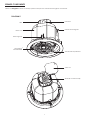
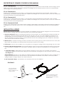
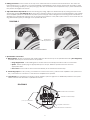
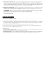
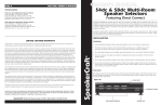
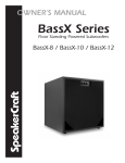
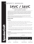
OWNER’S MANUAL
SC Pro Commercial
In-Ceiling Speaker System
SC Pro Commercial 8 | SC Pro Commercial 6 | SC Pro Commercial 4 | SC Pro Commercial Sub
SPEAKER COMPONENTS
Please use Diagram 1 below to identify speaker components mentioned throughout this manual.
DIAGRAM 1
Knockout
J-Box
Seismic Mounting Tab
Back Can
Mounting Foot
WavePlane™
Tweeter Baffle
Transformer Tap Selector
J-Box Lid
Terminal Connector Strip
1
DESCRIPTION OF SPEAKERS COVERED IN THIS MANUAL
SC Pro Commercial 8
Features an 8" polypropylene cone woofer, 1" pivoting dome tweeter, WavePlane™ tweeter baffle, wide-coverage, ported
design, and a built-in multi-tap transformer, capable of handling 8 ohm or 70V/100V systems. The SC Pro Commercial 8 is
ideal for large commercial applications.
SC Pro Commercial 6
Features an 61⁄2" polypropylene cone woofer, 1" pivoting dome tweeter, WavePlane™ tweeter baffle, wide-coverage,
ported design, and a built-in multi-tap transformer, capable of handling 8 ohm or 70V/100V systems. The SC Pro Commercial
6 is ideal for mid-size commercial applications.
SC Pro Commercial 4
Features an 41⁄2" polypropylene cone woofer, 1⁄2" pivoting dome tweeter, WavePlane™ tweeter baffle, wide-coverage,
ported design, and a built-in multi-tap transformer, capable of handling 8 ohm or 70V/100V systems. The SC Pro Commercial
4 is ideal for small commercial applications.
SC Pro Commercial Sub 8
Features an 8" polypropylene cone woofer, wide-coverage, ported design, and a built-in multi-tap transformer, capable of
handling 8 ohm or 70V/100V systems. The SC Pro Commercial Sub is ideal for enhancing bass in any commercial application.
INSTALLATION & WIRING
Because access above the ceiling is not always feasible, the installation process has been designed so that it can be done
from beneath the ceiling. Follow the simple steps below for a professional installation:
1. Check for Obstructions. Before confirming the placement of the speakers, you should carefully consider the location of ceiling joists, electrical, plumbing and other fixtures that may get in the way. If you are installing the speakers into an existing ceiling, you can locate obstructions by noting the placement of fixtures and, if possible, gaining access to an attic or crawl space for further analysis. A good stud-finder, found at any building supply store, will help you determine
where the joists are located in the ceiling.
2. Mark the Hole. A template for setting the hole is provided in the box (along with two paint mask inserts for use when paint-
ing). Position the template in the desired position and pencil an outline on the ceiling.
3. Cut the Hole. Once the hole is marked, use it as a guide to cut through the ceiling. Pull the wiring through the cutout hole.
4. Insert the S-Bracket Through the Hole. The included S-Bracket comes with two telescoping tile rails attached, which will fit across standard 24" ceiling tiles when extended to full length. Follow the directions appropriate for your ceiling type be-
low:
a. Suspended Ceilings - While folded, insert the S-Bracket through the cutout hole cut in the ceiling. Once inserted,
expand the S-Bracket and the tile rails, making sure that the bracket opening lines up with the cutout hole in the ceiling. (See Diagram 2)
SAFETY WARNING: Although you may adjust the S-Bracket along the tile rails for proper alignment with the ceiling hole, it is highly recommended that you DO NOT remove the tile rails from the S-Bracket at any time if used for Suspended Ceiling Installation. Doing so will pose in a serious safety risk.
b. Non-Suspended Ceilings - The S-Bracket is not necessary for this type of installation.
DIAGRAM 2
Insert the S-Bracket
through the cutout
hole, it should be in the
folded position.
S-Bracket
Tile Rail
2
Once it is through the cutout
hole, expand the S-Bracket,
then expand the telescoping
extension arms.
5. Utilizing Knockouts. Loosen screws at the top of the J-Box and remove the lid to reveal connections. The J-Box, has
four knockouts (two 1⁄2” and two 3⁄4”)to accommodate standard fittings. These can be removed as necessary to feed
wire in (connecting speaker) or out (loop through). After the connections are completed in step 7, place the lid back into position and tighten the screws.
6. Adjust Transformer Tap Selector. Before connecting any wiring, adjust the Transformer Tap by turning the knob to the
appropriate setting. (See Diagram 3) Be sure that the setting is correct for your system to avoid damage to the speaker
or the amplifier system. Do not allow a 70V/100V system to supply more wattage than the setting of the transformer or damage to the transformer will occur. Do not connect the speaker to a 70V/100V system when it is set to the 8 ohm set ting (transformer bypass) or damage to the speaker will occur.
DIAGRAM 3
Transformer
Tap Selector
SC Pro Commercial 8, SC Pro Commercial 6, SC Pro Commercial Sub 8
SC Pro Commercial 4
7. Speaker Wire Connections
a. Wiring Options. All wire connections are made inside the J-Box at the top of the speaker back can. (See Diagram 4)
There are three ways to connect wires to the speaker:
• Using stripped wires - Pull insulating sleeve off wire ends to reveal stripped wire for wire nut connection.
• Spade - Attach spade plugs to appropriate input or output. Slide the spade connectors onto the
appropriate tabs.
• Screw down - Screw wire or other connectors directly to the terminal connector strip.
b. Connecting Inputs. Use any COM (-) connection to connect the COM (-) wire from the amplifier to the speaker. Use
any + connection to connect the + wire from the amplifier to the speaker.
c. Loop Through. Any remaining connectors can be utilized to pass the signal on to additional speakers in the system.
Please note that this will result in a parallel connection.
DIAGRAM 4
For bare wire connection
Terminal Connector Strip
1
/2” & 3/4” Knockouts
COM
For spade connection
For screw down connection
3
8. Install Speaker into the Ceiling. Make sure the mounting feet are turned inward to clear the cutout hole, and insert the
speaker into the ceiling. Position the speaker into the hole. Note: The flange of the speaker is designed to flex and
conform to any small imperfections in the ceiling’s surface. Tighten the four screws on the front of the baffle only enough
to make the flange become snug against the ceiling. As you tighten the screws, the feet will automatically flip into an
outward position, thereby clamping the drywall between the feet and the flange. CAUTION: Over tightening may warp
the baffle, crack the ceiling, cause flange to distort, or make the grille difficult to install.
9. Utilizing the Seismic Mounting Tab. The Seismic Mounting Tab on the side of the speaker may be connected to a second-
ary support point. Construction codes in some regions may require the use of a secondary support point, it is recom-
mended to research construction codes in your area.
SAFETY WARNING: Although its use may be optional in your region, SpeakerCraft highly recommends using the Seismic
Mounting Tab with a secondary support point in the event that the ceiling tile collapses.
10. Insert the grille. Again, be sure that the transformer tap setting is correct for your system, then push the grille firmly into the slot in the speaker baffle.
PAINTING THE SPEAKERS
SC Pro Commercial speakers come standard with a neutral white finish, which will match almost any decor. However, it is
very easy to paint the speakers if desired.
The speaker baffle can be painted either prior to or after installation, using the procedure described below:
1. Gently clean the speakers with a lightly dampened cloth of mild solvent. DO NOT use abrasive materials (i.e. sandpaper
or steel wool) or harmful chemicals (i.e. gasoline, kerosene, acetone, MEK, paint thinner or harsh detergents) to clean
the speaker, as permanent damage may result.
2. Remove the grille and replace it with the included clear plastic paint mask prior to painting.
3. Apply at least two coats of either latex or oil-based paint. If using latex paint, apply an oil-based primer first for best
results. Paint the speakers by rolling, brushing, or spraying.
IMPORTANT NOTES
• If Painting the Speaker with the Ceiling - Remove the grille and replace it with the included clear plastic paint mask prior
to painting. When finished, remove the paint mask and replace the grille.
• When Painting the Grille - Remove the grille from the speaker. Spray painting is highly recommended, as the grille holes may clog if paint is rolled or brushed. SpeakerCraft recommends only light spray painting using 5 parts thinning agent to 1
part paint. When finished, replace the grille material inside the grille and insert the grille back into the speaker.
4
SPECIFICATIONS
SC Pro Commercial 8
SC Pro Commercial 6
Speaker Type:
Background / Foreground
In-Ceiling Speakers
Background / Foreground
In-Ceiling Speakers
Tweeter:
1" pivoting dome
1" pivoting dome
Woofer:
8" polypropylene cone
61⁄2" polypropylene cone
Transformer Taps:
70V: 64W, 32W, 16W, 8W
100V: 64W, 32W, 16W
8Ω (transformer bypass)
70V: 64W, 32W, 16W, 8W
100V: 64W, 32W, 16W
8Ω (transformer bypass)
Sensitivity:
88dB 1W/1m
88dB 1W/1m
Frequency Response:
56Hz - 20kHz - 3dB
50Hz - 22kHz -10dB
70Hz - 20kHz - 3dB
62Hz - 22kHz -10dB
Power Capacity:
60 Watts Continuous Pink
Noise
50 Watts Continuous Pink
Noise
Coverage Angle:
130º conical coverage
130º conical coverage
Directivity Factor (Q):
3.6 average 500Hz - 16kHz
3.51 average 500Hz - 16kHz
Directivity Index (DI):
5.23 average 500Hz - 16kHz
4.85 average 500Hz - 16kHz
Diameter x Depth:
1215⁄16" x 95⁄16"
105⁄16" x 87⁄16"
329 mm x 237 mm
262 mm x 214 mm
111⁄2"
87⁄8"
292 mm
225 mm
SC Pro Commercial 4
SC Pro Commercial Sub 8
Speaker Type:
Background / Foreground
In-Ceiling Speakers
Background / Foreground
In-Ceiling Speakers
Tweeter:
1
n/a
Woofer:
41⁄2" polypropylene cone
8" polypropylene cone
Transformer Taps:
70V: 32W, 16W, 8W, 4W
100V: 32W, 16W, 8W
8Ω (transformer bypass)
70V: 64W, 32W, 16W, 8W
100V: 64W, 32W, 16W
8Ω (transformer bypass)
Sensitivity:
85dB 1W/1m
87dB 1W/1m
Frequency Response:
88Hz - 20kHz - 3dB
78Hz - 24kHz -10dB
35Hz - 200Hz - 10dB
Power Capacity:
40 Watts Continuous Pink
Noise
60 Watts Continuous Pink
Noise
Coverage Angle:
130º conical coverage
Spherical (Omnidirectional)
Directivity Factor (Q):
3.53 average 500Hz - 16kHz
n/a
Directivity Index (DI):
4.71 average 500Hz - 16kHz
n/a
Cut Out Diameter:
Diameter x Depth:
Cut Out Diameter:
⁄2" pivoting dome
83⁄16" x 79⁄16"
1215⁄16" x 133⁄4"
208 mm x 192 mm
329 mm x 349 mm
63⁄4"
111⁄2"
171 mm
292 mm
As we incorporate design improvements, features and specifications may change without notice.
5
LIMITED LIFETIME WARRANTY
SpeakerCraft Inc. warrants to the original retail purchaser only that this SpeakerCraft product will be free from defects in materials and workmanship, provided the speaker was purchased from a SpeakerCraft Authorized Dealer.
Defective products must be shipped, together with proof of purchase, prepaid insured to the SpeakerCraft Authorized Dealer from whom they were purchased, or to the SpeakerCraft factory at the address listed on this installation instruction manual. Freight collect shipments will be refused. It is preferable to
ship this product in the original shipping container to lessen the chance of transit damage. In any case, the risk of loss or damage in transit is to be borne by
the purchaser. If, upon examination at the Factory or SpeakerCraft Authorized Dealer, it is determined that the unit was defective in materials or workmanship
at any time during this warranty period, SpeakerCraft or the SpeakerCraft Authorized Dealer will, at its option, repair or replace this product at no additional
charge, except as set forth below. If this model is no longer available and can not be repaired effectively, SpeakerCraft, at its sole option, may replace the
unit with a current model of equal or greater value. In some cases where a new model is substituted, a modification to the mounting surface may be required.
If mounting surface modification is required, SpeakerCraft assumes no responsibility or liability for such modification. All replaced parts and product become
the property of SpeakerCraft Inc. Products replaced or repaired under this Warranty will be returned to the original retail purchaser, within a reasonable time,
freight prepaid.
This Warranty does not include service or parts to repair damage caused by accident, disaster, misuse, abuse, negligence, inadequate packing or shipping
procedures, commercial use, voltage inputs in excess of the rated maximum of the unit, or service, repair or modification of the product which has not been
authorized or approved by SpeakerCraft. This Warranty also excludes normal cosmetic deterioration caused by environmental conditions. This warranty will
be void if the Serial Number on the product has been removed, tampered with or defaced.
This Warranty is in lieu of all other expressed warranties. If the product is defective in materials or workmanship as warranted
above, the purchaser’s sole remedy shall be repair or replacement as provided above. In no event will SpeakerCraft be liable
for any incidental or consequential damages arising out of the use or inability to use the product, even if SpeakerCraft Inc. or a
SpeakerCraft Inc. Authorized Dealer has been advised of the possibility of such damages, or for any claim by any other party.
Some states do not allow the exclusion or limitation of consequential damages, so the above limitation and exclusion may not
apply.
All implied warranties on the product are limited to the duration of this expressed Warranty. Some states do not allow limitation
on the length of an implied warranty. If the original retail purchaser resides in such a state, this limitation does not apply.
SpeakerCraft offers a variety of accessories to make your installation of this and other SpeakerCraft products easy, economical, and professional.
Contact your authorized SpeakerCraft Dealer for more information. For technical inquires, please call 1-800-448-0976 or e-mail us at techsupport@
speakercraft.com. We are available to assist you every weekday, except holidays, between the hours of 7:00 a.m. and 5:00 p.m. PST.
6
940 Columbia Avenue, Riverside, CA 92507 | USA (800) 448 0976 Fax (951) 787 8747 International +1 951 787 0543 | www.speakercraft.com
LIT L13-42455(rev1)