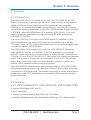
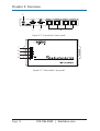
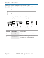
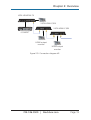
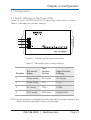
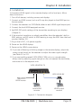
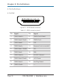
1
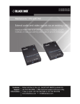
Chapter VSPX-HDMI1X4-TX VSPX-HDMI-CSRX VSPX-HDMI-RX MediaCento™ HX Transmitter and Receivers Extend HDMI signals over CATx cable. BLACK BOX • VSPX-HDMI-RX works with a VSPX-HDMI1X4-TX to connect ® an HD or 3D screen in a MediaCento HX deployment. •VSPX-CSRX works with a VSPX-HDMI1X4-TX to connect an HD or 3D screen and can be cascaded to a second display. Customer Support Information Order toll-free in the U.S.: Call 877-877-BBOX (outside U.S. call 724-746-5500) • FREE technical support 24 hours a day, 7 days a week: Call 724-746-5500 or fax 724-746-0746 • Mailing address: Black Box Corporation, 1000 Park Drive, Lawrence, PA 15055-1018 Web site: www.blackbox.com • E-mail: [email protected] Trademarks Used in this Manual Trademarks Used in this Manual Black Box and the Double Diamond logo are registered trademarks, and iCOMPEL and MediaCento are trademarks, of BB Technologies, Inc. Any other trademarks mentioned in this manual are acknowledged to be the property of the trademark owners. Page 2 724-746-5500 | blackbox.com FCC and IC RFI Statements/NOM Statement FEDERAL COMMUNICATIONS COMMISSION AND INDUSTRY CANADA RADIO FREQUENCY INTERFERENCE STATEMENTS This equipment generates, uses, and can radiate radio-frequency energy, and if not installed and used properly, that is, in strict accordance with the manufacturer’s instructions, may cause interference to radio communication. It has been tested and found to comply with the limits for a Class A computing device in accordance with the specifications in Subpart B of Part 15 of FCC rules, which are designed to provide reasonable protection against such interference when the equipment is operated in a commercial environment. Operation of this equipment in a residential area is likely to cause interference, in which case the user at his own expense will be required to take whatever measures may be necessary to correct the interference. Changes or modifications not expressly approved by the party responsible for compliance could void the user’s authority to operate the equipment. This digital apparatus does not exceed the Class A limits for radio noise emission from digital apparatus set out in the Radio Interference Regulation of Industry Canada. Le présent appareil numérique n’émet pas de bruits radioélectriques dépassant les limites applicables aux appareils numériques de classe A prescrites dans le Règlement sur le brouillage radioélectrique publié par Industrie Canada. Normas Oficiales Mexicanas (NOM) Electrical Safety Statement INSTRUCCIONES DE SEGURIDAD 1. Todas las instrucciones de seguridad y operación deberán ser leídas antes de que el aparato eléctrico sea operado. 2. Las instrucciones de seguridad y operación deberán ser guardadas para referencia futura. 3. Todas las advertencias en el aparato eléctrico y en sus instrucciones de operación deben ser respetadas. 4. Todas las instrucciones de operación y uso deben ser seguidas. 724-746-5500 | blackbox.com Page 3 NOM Statement 5. El aparato eléctrico no deberá ser usado cerca del agua — por ejemplo, cerca de la tina de baño, lavabo, sótano mojado o cerca de una alberca, etc. 6. El aparato eléctrico debe ser usado únicamente con carritos o pedestales que sean recomendados por el fabricante. 7. El aparato eléctrico debe ser montado a la pared o al techo sólo como sea recomendado por el fabricante. 8. Servicio—El usuario no debe intentar dar servicio al equipo eléctrico más allá a lo descrito en las instrucciones de operación. Todo otro servicio deberá ser referido a personal de servicio calificado. 9. El aparato eléctrico debe ser situado de tal manera que su posición no interfiera su uso. La colocación del aparato eléctrico sobre una cama, sofá, alfombra o superficie similar puede bloquea la ventilación, no se debe colocar en libreros o gabinetes que impidan el flujo de aire por los orificios de ventilación. 10.El equipo eléctrico deber ser situado fuera del alcance de fuentes de calor como radiadores, registros de calor, estufas u otros aparatos (incluyendo amplificadores) que producen calor. 11. El aparato eléctrico deberá ser connectado a una fuente de poder sólo del tipo descrito en el instructivo de operación, o como se indique en el aparato. 12. Precaución debe ser tomada de tal manera que la tierra fisica y la polarización del equipo no sea eliminada. 13. Los cables de la fuente de poder deben ser guiados de tal manera que no sean pisados ni pellizcados por objetos colocados sobre o contra ellos, poniendo particular atención a los contactos y receptáculos donde salen del aparato. 14.El equipo eléctrico debe ser limpiado únicamente de acuerdo a las recomendaciones del fabricante. 15. En caso de existir, una antena externa deberá ser localizada lejos de las lineas de energia. 16.El cable de corriente deberá ser desconectado del cuando el equipo no sea usado por un largo periodo de tiempo. Page 4 724-746-5500 | blackbox.com NOM Statement/Safety Notice 17. Cuidado debe ser tomado de tal manera que objectos liquidos no sean derramados sobre la cubierta u orificios de ventilación. 18.Servicio por personal calificado deberá ser provisto cuando: A: El cable de poder o el contacto ha sido dañado; u B: Objectos han caído o líquido ha sido derramado dentro del aparato; o C: El aparato ha sido expuesto a la lluvia; o D: El aparato parece no operar normalmente o muestra un cambio en su desempeño; o E: El aparato ha sido tirado o su cubierta ha sido dañada. Safety Notice Please read and follow the safety instructions to protect yourself from possible injury and to minimize the risk of damage to the units. • Follow all instructions and warnings maked on the units. • Do not attempt to service the units yourself, except where explained in this manual. • Provide proper ventilation and air circulation and do not use near water. • Keep objects that might damage the device away, and make sure the placement of the units are on stable surfaces. • Use only the power adapter, power cords, and connection cables designed for the units. • Do not use liquid or aerosol cleaners to clean this unit. Always unplug the power to the device before cleaning. 724-746-5500 | blackbox.com Page 5 Table of Contents Table of Contents 1. Specifications................................................................................................7 2. Overview . ..............................................................................................9 2.1 Introduction........................................................................................9 2.2 Features...............................................................................................9 2.2.1 VSPX-HDMI1X4-TX, VSPX-HDMI-RX, VSPX-HDMI-CSRX.....9 2.2.2 Additional Features for VSPX-HDMI1X4-TX.........................10 2.2.3 Additional Features for VSPX-HDMI-RX...............................10 2.2.4 Additional Features for VSPX-HDMI-CSRX..........................10 2.3 What’s Included................................................................................ 11 2.3.1 VSPX-HDMI1X4-TX............................................................... 11 2.3.2 VSPX-HDMI-RX..................................................................... 11 2.3.3 VSPX-HDMI-CSRX................................................................ 11 2.4 Hardware Description....................................................................... 11 2.4.1 1X4 Transmitter (VSPX-HDMI1X4-TX).................................. 11 2.4.2 Receiver (VSPX-HDMI-RX)....................................................14 2.4.3 Cascadable Receiver (VSPX-HDMI-CSRX)............................16 2.5 Application Diagrams........................................................................18 3. Configuration.............................................................................................21 3.1 Switch Settings on the Transmitter...................................................21 3.2 EDID Learning...................................................................................22 4. Installation . ............................................................................................23 5. Pin Definitions............................................................................................24 5.1 HDMI . ............................................................................................24 5.2 RJ-45/CATx.......................................................................................25 6. Performance Guide for HDMI Over Category 5/6 Cable Transmission.....26 7. Troubleshooting.........................................................................................27 7.1 Contacting Black Box........................................................................27 7.2 Shipping and Packaging...................................................................27 Page 6 724-746-5500 | blackbox.com Chapter 1: Specifications 1. Specifications Audio Support — Surround sound (up to 7.1ch) or stereo digital audio Equalization — VSPX-HDMI1X4-TX: Built-in; VSPX-HDMI-CSRX: 8-level digital output signal equalization ESD Protection — (1) human body model: ±19 kV (air-gap discharge) and ±12 kV (contact discharge); (2) core chipset: ±8 kV HDCP Compliance — Yes HDMI Compliance — HDMI deep color and 3D Housing — Metal enclosure Input DDC Signal — 5 Volts (peak-to-peak, TTL) Input TMDS Signal — VSPX-HDMI1X4-TX: 1.1 Volts (peak-to-peak); VSPX-HDMI-RX, VSPX-HDMI-CSRX: 1.2 Volts (peak-to-peak) Mounting — Wallmounting ears with screws PCB Stack-up — 4-layer board (impedance control: differential 100 ohms, single 50 ohms) Role — VSPX-HDMI1X4-TX: Transmitter; VSPX-HDMI-RX: Receiver; VSPX-HDMI-CSRX: Cascadable receiver Transmission Over UTP (24-bit color) — VSPX-HDMI1X4-TX, VSPX-HDMI-CSRX: Full HD (1080p): 130 ft. (40 m) over CATx cable; HD (720p/1080i): 200 ft. (60 m) over CATx cable Video Bandwidth — Single-link 225 MHz (6.75 Gbps) Video Support — 480i/480p/720p/1080i/1080p up to 36-bit color User Controls — VSPX-HDMI1X4-TX: (4) DIP switches for EDID control; VSPX-HDMI-RX: (1) 8-level digital HDMI signal equalization rotary control switch; VSPX-HDMI-CSRX: 16-level HDMI signal equalization and audio rotary control Connectors — VSPX-HDMI1X4-TX: Input: (1) HDMI, Output: (4) RJ-45, (1) HDMI; VSPX-HDMI-RX: Input: (1) RJ-45 with (2) LED indicators ([1] Power, [1] Link), Output: (1) HDMI Type A (19-pin female); VSPX-HDMI-CSRX: Input: (1) HDMI Type A (19-pin female), Output: (1) HDMI, (1) RJ-45 with (2) LED indicators ([1] Power, [1] Link), (1) 3.5-mm audio earphone jack for stereo audio (2-channel PCM only) 724-746-5500 | blackbox.com Page 7 Chapter 1: Specifications Indicators — VSPX-HDMI1X4-TX: (2) LEDs: (1) RED Power, (1) GREEN Signal; VSPX-HDMI-RX: (2) RJ-45 LEDs: Power; VSPX-HDMI-CSRX: (6) LEDs: (1) RED Power, (1) GREEN HDMI/DVI, (2) RJ-45 Signal in status, (2) RJ-45 Signal out power Temperature Tolerance — Operating: +32 to +104° F (0 to +40° C); Storage: -4 to +140° F (-20 to +60° C) Relative Humidity — 20 to 90%, noncondensing Power — VSPX-HDMI1X4-TX: 5-VDC, 4 A, 13 watts (maximum); VSPX-HDMI-RX: 5-VDC, 4-A, 1 watt (maximum); VSPX-HDMI-CSRX: 5-VDC, 4-A, 7.5 watts Size — VSPX-HDMI1X4-TX: 1.1"H x 4.3"W x 7.6"D (2.7 x 11 x 19.4 cm); VSPX-HDMI-RX: 1.1"H x 3.5"W x 6.8"D (2.7 x 9 x 17.5 cm); VSPX-HDMI-CSRX: 1"H x 4.2"W x 7"D (2.6 x 10.7 x 17.9 cm) Weight — VSPX-HDMI1X4-TX: 1.3 lb. (0.6 kg); VSPX-HDMI-RX: 0.4 lb. (0.2 kg); VSPX-HDMI-CSRX: 1.2 lb. (0.5 kg) Page 8 724-746-5500 | blackbox.com Chapter 2: Overview 2. Overview 2.1 Introduction The VSPX-HDMI1X4-TX transmitter works with the VSPX-HDMI-RX or VSPXHDMI-CSRX receiver to extend high-definition video and high-quality audio to different locations over a long distance. The transmitters are cascadable, enabling you to increase the number of total displays. The input HDMI source can be duplicated and distributed to up to four HDMI enabled displays linked by CAT5/5e/6 cables with HDMI over CAT5 receivers (VSPX-HDMI). If you only need a single port transmitter, buy the compatible 3D HDMI extender kit (VX-HDMI-TP-3D40M). The VSPX-HDMI1X4-TX also has a local HDMI output for monitoring. With built-in equalization, the input HDMI cable can be extended up to 66 feet (20 meters) using Full HD, making the overall transmission distance better when compared to generic HDMI splitters. The VSPX-HDMI-CSRX receiver works with the VSPX-HDMI1X4 transmitter, VSPX-HDMI-RX receiver, or VX-HDMI-TP-3D40M extender kit to distribute HDMI/DVI video sources to up to ten displays in a daisychained connection via CAT5/5e. By using the VSPX-HDMI1X4-TX transmitter and making four separate chains, the number of displays can be increased to a total of 40. The cascade ability allows pure digital video and audio broadcast station by station and extends HDMI compliant video and audio anywhere. The VSPX-HDMI-RX receiver works with the transmitter or VSPX-HDMI-CSRX cascadable receiver to extend high-definition video and high-quality audio over a distance via CAT5/5e/6 cable. The receiver works with an HDMI transmitter or splitter over single CAT5 and enables you to extend HDMI compliant displays almost anywhere. 2.2 Features 2.2.1 VSPX-HDMI1X4-TX, VSPX-HDMI-RX, VSPX-HDMI-CSRX • Support HDMI deep color and 3D. • HDCP compliant. • Transmits uncompressed digital HDMI over CATx cable. • Perfectly integrated with other compatible HDMI over CATx series products. 724-746-5500 | blackbox.com Page 9 Chapter 2: Overview 2.2.2 Additional Features for VSPX-HDMI1X4-TX • Regenerates the HDMI signal. • HDMI local output for monitoring. • Supports default HDMI EDID and can learn the EDID of displays. • Extends up to 66 feet (20 m) of input HDMI cable. • Outputs video up to 200 feet (60 m) over CATx cable using HD (720p/1080p). • Outputs video up to 130 feet (40 m) over CATx cable using Full HD (1080p). • Wallmountable. NOTE: The cable length depends on the characteristics and quality of the cables. Higher resolutions and longer transmission distances require low-skew cables (<25 ns/100 m) for best performance. We recommend using solid core CAT6 cable. 2.2.3 Additional Features for VSPX-HDMI-RX • Extends up to 200 feet (60 m) over CATx cable using HD (720p/1080i). • Extends up to 130 feet (40 m) over CATx cable using Full HD (1080p). • Wallmountable. NOTE: The cable length depends on the characteristics and quality of the cables. Higher resolutions and longer transmission distances require low-skew cables (<25 ns/100 m) for best performance. We recommend using solid core CAT6 cable. 2.2.4 Additional Features for VSPX-HDMI-CSRX • Regenerates and outputs the HDMI signal. • Support for stereo audio analog or 7.1ch audio via HDMI interface. • Extends up to 200 feet (60 m) (720p/1080i) over CATx cable. • Extends up to 130 feet (40 m) (1080p) over CATx cable. • Up to three layers of cascaded units can be used to reach a total distance of up to 393 feet (120 m). • Wallmountable. NOTE: The cable length depends on the characteristics and quality of the cables. Higher resolutions and longer transmission distances require low-skew cables (<25 ns/100 m) for best performance. We recommend using solid core CAT6 cable. Page 10 724-746-5500 | blackbox.com Chapter 2: Overview 2.3 What’s Included Your package should include the following items. If anything is missing or damaged, contact Black Box Technical Support at 724-746-5500 or [email protected]. 2.3.1 VSPX-HDMI1X4-TX • (1) 1X4 Transmitter (VSPX-HDMI1X4-TX) • (1) 5-VDC, international 4-A in-line power supply unit with US power cord • (2) mounting screws • This user’s manual 2.3.2 VSPX-HDMI-RX • (1) Receiver (VSPX-HDMI-RX) • (1) 5-VDC, international 4-A in-line power supply unit with US power cord • (2) mounting screws • This user‘s manual 2.3.3 VSPX-HDMI-CSRX • (1) Cascadable Receiver (VSPX-HDMI-CSRX) • (1) 5-VDC, international 4-A in-line power supply unit with US power cord • (2) mounting screws • This user’s manual 2.4 Hardware Description 2.4.1 1 x 4 Transmitter (VSPX-HDMI1X4-TX) Figures 2-1, 2-2, and 2-3 show the front, back, and top panels of the transmitter. Table 2-1 describes its components. 1 2 Figure 2-1. Transmitter’s front panel. 724-746-5500 | blackbox.com Page 11 Chapter 2: Overview 3 4 5 6 Figure 2-2. Transmitter’s back panel. 7 8 9 10 Figure 2-3. Transmitter’s top panel. Page 12 724-746-5500 | blackbox.com Chapter 2: Overview Table 2-1. Transmitter’s components. Number Component Description 1 Power LED ON when power to the unit is on. OFF when power is off. 2 Signal LED ON when HDMI source signal is detected. OFF when no HDMI signal is detected. 3 +5 VDC power connector Connects to 5 VDC, 4 A interlocking power adapter. 4 HDMI input connector Connects to HDMI source. 5 HDMI output connector Links to HDMI output for local monitor. 6 (4) RJ-45 connectors CATx output 1–4 7 SW1 2D/3D mode 8 SW2 Audio mode 9 SW3 HD mode 10 SW4 Learn EDID mode 724-746-5500 | blackbox.com Page 13 Chapter 2: Overview 2.4.2 Receiver (VSPX-HDMI-RX) Figures 2-4 and 2-5 show the front and back panels of the receiver. Table 2-2 describes its components. 1 2 3 4 Figure 2-4. Receiver’s front panel. 5 6 Figure 2-5. Receiver’s back panel. Page 14 724-746-5500 | blackbox.com Chapter 2: Overview Table 2-2. Receiver’s components. Number Component Description 1 Interlocking power jack Connects to +5 VDC power supply unit. 2 Power LED Lights when power is on. 3 RJ-45 connector Interconnect. 4 Power LED Lights when power is on. 5 8-position switch Adjust the 8-level equalization control to the received HDMI male-male cable. The HDMI signal level varies from 0 (strongest) to 7 (weakest) for respective transmission length from longest possible range to short distance. Adjust the signal level from 7 to 0 and stop turning the rotary switch when the audio/video is playing normally. Inappropriate signal level setting may cause an over-power condition that could damage the converter. 6 HDMI output connector Connect to an HDMI display with an HDMI male-male cable. 724-746-5500 | blackbox.com Page 15 Chapter 2: Overview 2.4.3 Cascadable Receiver (VSPX-HDMI-CSRX) Figures 2-6 and 2-7 show the front and back panels of the cascadable receiver. Table 2-3 describes its components. 1 Figure 2-6. Cascadable receiver’s front panel. 9 10 2 3 11 12 4 5 6 7 Figure 2-7. Cascadable receiver’s back panel. 8 Table 2-3. Cascadable receiver’s components. Number Component Description 1 Power LED Lights when power to the unit is on. 2 HDMI/DVI LED ON when HDMI signal is detected. OFF when DVI signal is detected. Page 16 724-746-5500 | blackbox.com Chapter 2: Overview Table 2-3 (Continued). Cascadable receiver’s components. Number Component Description 3 16-level rotary control switch Adjust the 16-level equalization control corresponding to the transmission distance of receiving HDMI signals. For surround sound audio output, adjust from 0 to 7 (longest-to-shortest transmission length). For stereo audio output, adjust from 8 to F (longest-toshortest transmission length). We recommend adjusting from 7 to 0 or from F to 8 to find the optimal visual result. Adjust the signal level from 7 to 0 or F to 8 and stop turning the rotary switch when the audio/video is playing normally. Inappropriate signal level setting may cause an over-power condition that could damage the converter. 4 RJ-45 signal input Interconnect input. 5 3.5-mm connector Audio out: plug in a local speaker here. 6 HDMI output connector Connect to a local HDMI display with an HDMI male-male cable here, or link to another cascadable receiver for cascading. 7 RJ-45 signal output Interconnect output. 8 Interlocking power jack Connects to +5 VDC, 4A power supply unit. 724-746-5500 | blackbox.com Page 17 Chapter 2: Overview Table 2-3 (Continued). Cascadable receiver’s components. Number Component Description 9 Link LED Lights when a link is present. 10 Link LED Lights when a link is present. 11 Power LED Lights when power to the port is on. 12 Power LED Lights when power to the port is on. 2.5 Application Diagrams Figures 2-8 through 2-10 show typical application diagrams for the transmitter, receiver, and cascadable receiver. VSPX-HDMI1X4-TX VSPX-HDMI-RX HDMI source Local HDMI monitor HDMI output monitor Figure 2-8. Connection diagram #1. Page 18 724-746-5500 | blackbox.com Chapter 2: Overview VSPX-HDMI1X4-TX VSPX-HDMI-CSRX VSPX-HDMI-CSRX iCOMPEL ™ HDMI output monitor HDMI output monitor Figure 2-9. Connection diagram #2. 724-746-5500 | blackbox.com Page 19 Chapter 2: Overview HDMI monitor iCOMPEL™ VSPX-HDMI-CSRX CATx cable 64 ft. (40 m) CATx cable 64 ft. (40 m) VSPX-HDMI1X4-TX Local HDMI output monitor VSPX-HDMI-RX CATx cable 128 ft. (40 m) VSPX-HDMI-RX VSPX-HDMI-RX HDMI monitor HDMI monitor HDMI monitor Figure 2-10. Connection diagram #3. Page 20 724-746-5500 | blackbox.com Chapter 3: Configuration 3. Configuration 3.1 Switch Settings on the Transmitter Figure 3-1 shows the VSPX-HDMI1X4-TX transmitter board’s switch locations. Table 3-1 describes the switches’ settings. 1 2 3 4 Figure 3-1. Switches on the transmitter board. Table 3-1. Transmitter board’s switch settings. Number DIP switch Name Left Position Setting Right Position Setting 1 Video mode 2D display 3D display 2 Audio mode 2 ch 7.1 ch 3 HD mode 720p 1080p 4 EDID mode EDID learn Default EDID NOTE: Instant switching is enabled only when the video and audio setting of the source has been adjusted to Auto or Passthrough. 724-746-5500 | blackbox.com Page 21 Chapter 3: Configuration 3.2 EDID Learning 1. Power on the transmitter. Connect the display that you want to learn the EDID to the HDMI output connector. 2. To learn the display’s EDID for the source device connected to the HDMI output on the transmitter, set EDID mode to the left position. Power on the transmitter and wait for about five seconds to complete the EDID learning process. Page 22 724-746-5500 | blackbox.com Chapter 4: Installation 4. Installation To broadcast HDMI signals to four remote displays with a local port, follow these instructions. 1. Turn off all devices, including sources and displays. 2. Connect an HDMI source (such as a Blu-ray disc player) to the HDMI port on the transmitter. 3. Connect the receivers via CAT5/5e/6 cables to each HDMI signal output port. 4. Connect the local HDMI equipped monitor. 5. Set EDID DIP switch settings of the transmitter according to your displays (Chapter 3). 6. If the monitor’s resolution or refresh rate differs from the extender’s built in EDID settings, set DIP switch to EDID learning to copy the EDID from the local monitor (Section 3.2). 7. Plug in the 5-VDC, 4-A power supplies. 8. Power on the HDMI displays. 9. Power on the HDMI source device. 10. If you see a flickering or blinking image on the remote displays, adjust the rotary control switch on the receivers to adjust the video signal strength (see Table 2-2 or 2-3). 11. If you are installing several VSPX-HDMI-CSRX units in a cascade setup, always start by adjusting signal strength on the unit nearest the transmitter, and move on to the adjacent units. VSPX-HDMI1X4-TX VSPX-HDMI-RX HDMI source Local HDMI monitor HDMI output monitor Figure 4-1. Connection diagram. 724-746-5500 | blackbox.com Page 23 Chapter 5: Pin Definitions 5. Pin Definitions 5.1 HDMI Figure 5-1. HDMI female connector. Table 5-1. HDMI connector pinout. Pin Signal Pin Signal 1 TMDS Data2+ 11 TMDS Clock Shield 2 TMDS Data2 Shield 12 TMDS Clock 3 TMDS Data2- 13 CEC 4 TMDS Data1+ 14 Reserved (not connected) 5 TMDS Data 1 Shield 15 SCL 6 TMDS Data1- 16 SDA 7 TMDS Data0+ 17 DC/CEC Ground 8 TMDS Data0 Shield 18 +5 V Power 9 TMDS Data0- 19 Hot Plug Detect 10 TMDS Clock+ — — Page 24 724-746-5500 | blackbox.com Chapter 5: Pin Definitions 5.2 RJ-45/CATx Figure 5-2. RJ-45 connector. Table 5-2. RJ-45 CATx TIA/EIA-568B connector pinout. Pin T568A Pair T568A Color T568B Pair T568B Color 1 3 White-Green 2 White-Orange 2 3 Green 2 Orange 3 2 White-Orange 3 White-Green 4 1 Blue 1 Blue 5 1 White-Blue 1 White-Blue 6 2 Orange 3 Green 7 4 White-Brown 4 White-Brown 8 4 Brown 4 Brown 724-746-5500 | blackbox.com Page 25 Chapter 6: Performance Guide 6. Performance Guide for HDMI Over Category 5/6 Cable Transmission Table 6-1. Cable performance guide. Performance Rating Type of CAT5/6 Cable Wiring Shielding CAT5 CAT5e CAT6 Unshielded (UTP) *** ***** ***** Shielded (STP) *** *** **** Unshielded (UTP) * ** ** Shielded (STP) * * ** Solid Stranded Termination Page 26 Use EIA/TIA-568-B termination. 724-746-5500 | blackbox.com Chapter 7: Troubleshooting 7. Troubleshooting 7.1 Contacting Black Box If you determine that your transmitter, receiver, or cascadable receiver is malfunctioning, do not attempt to alter or repair the unit. It contains no user-serviceable parts. Contact Black Box Technical Support at 724-746-5500 or [email protected]. Before you do, make a record of the history of the problem. We will be able to provide more efficient and accurate assistance if you have a complete description, including: • the nature and duration of the problem. • when the problem occurs. • the components involved in the problem. • any particular application that, when used, appears to create the problem or make it worse. 7.2 Shipping and Packaging If you need to transport or ship your transmitter, receiver, or cascadable receiver: • Package it carefully. We recommend that you use the original container. • If you are returning the unit, make sure you include everything you received with it. Before you ship for return or repair, contact Black Box to get a Return Authorization (RA) number. 724-746-5500 | blackbox.com Page 27 Chapter Black Box Tech Support: FREE! Live. 24/7. Tech support the way it should be. Great tech support is just 30 seconds away at 724-746-5500 or blackbox.com. About Black Box Black Box provides an extensive range of networking and infrastructure products. You’ll find everything from cabinets and racks and power and surge protection products to media converters and Ethernet switches all supported by free, live 24/7 Tech support available in 30 seconds or less. © Copyright 2013. Black Box Corporation. All rights reserved. VSPX-HDMI1X4-TX, version 2 724-746-5500 | blackbox.com