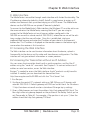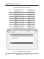
1
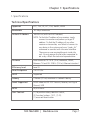
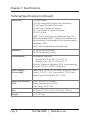
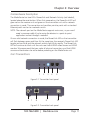
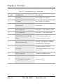
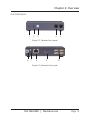
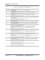
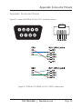
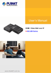
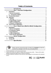
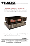
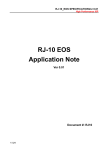
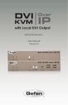
UVX-HDMI-POE-TX.. UVX-HDMI-POE-RX MediaCento™ IPX USB Transmitter and Receiver Extend video, audio, and USB signals BLACK BOX via an existing LAN. ® Distribute HDMI video, audio, and USB to an unlimited number of displays using IP multicast. Customer Support Information Order toll-free in the U.S.: Call 877-877-BBOX (outside U.S. call 724-746-5500) • FREE technical support 24 hours a day, 7 days a week: Call 724-746-5500 or fax 724-746-0746 • Mailing address: Black Box Corporation, 1000 Park Drive, Lawrence, PA 15055-1018 Web site: www.blackbox.com • E-mail: [email protected] Trademarks Used in this Manual Trademarks Used in this Manual Black Box and the Double Diamond logo are registered trademarks, and MediaCento is a trademark, of BB Technologies, Inc. Bonjour and Apple are registered trademarks of Apple, Inc. Windows is a registered trademark of Microsoft Corporation. UL is a registered trademark of Underwriters’ Laboratories. Any other trademarks mentioned in this manual are acknowledged to be the property of the trademark owners. Page 2 724-746-5500 | blackbox.com FCC RFI Statement FEDERAL COMMUNICATIONS COMMISSION AND INDUSTRY CANADA RADIO FREQUENCY INTERFERENCE STATEMENTS This equipment generates, uses, and can radiate radio-frequency energy, and if not installed and used properly, that is, in strict accordance with the manufacturer’s instructions, may cause interference to radio communication. It has been tested and found to comply with the limits for a Class A computing device in accordance with the specifications in Subpart B of Part 15 of FCC rules, which are designed to provide reasonable protection against such interference when the equipment is operated in a commercial environment. Operation of this equipment in a residential area is likely to cause interference, in which case the user at his own expense will be required to take whatever measures may be necessary to correct the interference. Changes or modifications not expressly approved by the party responsible for compliance could void the user’s authority to operate the equipment. This digital apparatus does not exceed the Class A limits for radio noise emission from digital apparatus set out in the Radio Interference Regulation of Industry Canada. Le présent appareil numérique n’émet pas de bruits radioélectriques dépassant les limites applicables aux appareils numériques de classe A prescrites dans le Règlement sur le brouillage radioélectrique publié par Industrie Canada. Normas Oficiales Mexicanas (NOM)Electrical Safety Statement INSTRUCCIONES DE SEGURIDAD 1. Todas las instrucciones de seguridad y operación deberán ser leídas antes de que el aparato eléctrico sea operado. 2. Las instrucciones de seguridad y operación deberán ser guardadas para referencia futura. 3. Todas las advertencias en el aparato eléctrico y en sus instrucciones de operación deben ser respetadas. 724-746-5500 | blackbox.com Page 3 NOM Statement 4. Todas las instrucciones de operación y uso deben ser seguidas. 5. El aparato eléctrico no deberá ser usado cerca del agua—por ejemplo, cerca de la tina de baño, lavabo, sótano mojado o cerca de una alberca, etc. 6. El aparato eléctrico debe ser usado únicamente con carritos o pedestales que sean recomendados por el fabricante. 7. El aparato eléctrico debe ser montado a la pared o al techo sólo como sea recomendado por el fabricante. 8. Servicio—El usuario no debe intentar dar servicio al equipo eléctrico más allá a lo descrito en las instrucciones de operación. Todo otro servicio deberá ser referido a personal de servicio calificado. 9. El aparato eléctrico debe ser situado de tal manera que su posición no interfiera su uso. La colocación del aparato eléctrico sobre una cama, sofá, alfombra o superficie similar puede bloquea la ventilación, no se debe colocar en libreros o gabinetes que impidan el flujo de aire por los orificios de ventilación. 10.El equipo eléctrico deber ser situado fuera del alcance de fuentes de calor como radiadores, registros de calor, estufas u otros aparatos (incluyendo amplificadores) que producen calor. 11. El aparato eléctrico deberá ser connectado a una fuente de poder sólo del tipo descrito en el instructivo de operación, o como se indique en el aparato. 12. Precaución debe ser tomada de tal manera que la tierra fisica y la polarización del equipo no sea eliminada. 13. Los cables de la fuente de poder deben ser guiados de tal manera que no sean pisados ni pellizcados por objetos colocados sobre o contra ellos, poniendo particular atención a los contactos y receptáculos donde salen del aparato. 14.El equipo eléctrico debe ser limpiado únicamente de acuerdo a las recomendaciones del fabricante. 15. En caso de existir, una antena externa deberá ser localizada lejos de las lineas de energia. Page 4 724-746-5500 | blackbox.com NOM Statement 16.El cable de corriente deberá ser desconectado del cuando el equipo no sea usado por un largo periodo de tiempo. 17. Cuidado debe ser tomado de tal manera que objectos liquidos no sean derramados sobre la cubierta u orificios de ventilación. 18.Servicio por personal calificado deberá ser provisto cuando: A: El cable de poder o el contacto ha sido dañado; u B: Objectos han caído o líquido ha sido derramado dentro del aparato; o C: El aparato ha sido expuesto a la lluvia; o D: E l aparato parece no operar normalmente o muestra un cambio en su desempeño; o E: El aparato ha sido tirado o su cubierta ha sido dañada. 724-746-5500 | blackbox.com Page 5 Table of Contents Table of Contents 1. Specifications................................................................................................... 7 2. Overview .................................................................................................... 9 2.1Introduction............................................................................................. 9 2.2Features................................................................................................... 9 2.3 Multicast Transmitter and Receiver Exclusive Functions....................... 10 2.4 What’s Included.................................................................................... 10 2.5 Additional Items You Will Need............................................................ 10 2.6 Hardware Description............................................................................ 11 2.6.1Transmitters.............................................................................. 11 2.6.2Receivers................................................................................... 13 3. Installation .................................................................................................. 15 3.1 System Requirements for PoE............................................................... 15 3.2 Installing the Transmitter and Receiver................................................. 15 3.3 Basic Setup/Uses................................................................................... 15 3.3.1Unicast...................................................................................... 16 3.3.2Multicast................................................................................... 16 4.Operation.................................................................................................. 17 5. USB Extension................................................................................................ 18 6 Serial and Telnet Extension............................................................................ 19 7. Advanced Commands....................................................................................22 8. Web Interface.................................................................................................23 8.1 Accessing the Web Interface.................................................................23 8.2 Accessing the Transmitter without an IP Address.................................23 8.3 Accessing the Web Interface for a Transmitter or Receiver with an IP Address................................................................................. 25 Appendix. Connector Pinouts................................................................................29 Page 6 724-746-5500 | blackbox.com Chapter 1: Specifications 1. Specifications Technical Specifications Approvals FCC, TUV, CE, UL®, CSA, RoHS2, WEEE Bandwidth 120 Mbps maximum Default IP Address 169.254.x.x (with no DHCP address) NOTE: T o find the IP address of any receiver, simply connect to monitor and power up to get IP address. To find the IP address of any other receiver or transmitter, use Telnet to connect to any device in the system and use a “node_list” command or connect with the serial interface. There are no user-serviceable parts inside the unit. Do not remove the lid unless requested to do so by a Black Box technical representative. Distance From source to TX: 16 ft. (5 m) maximum, HDMI; Between TX and RX: 328 ft. (100 m) Ethernet standard Efficiency Level Level IV Heat Dissipation 3.41 BTU/hr. HDCP Supported Latency 2 frames (33 ms) maximum + network latency Leads Supported HDMI video and RS-232 Transmit, Receive, and Signal Ground, USB MTBF 90,000 hours User Controls (1) 16-position rotary selection switch; (2) Function buttons: (1) F1, (1) F2; (1) recessed Reset button 724-746-5500 | blackbox.com Page 7 Chapter 1: Specifications Technical Specifications (continued) Connectors (1) HDMI female, (1) RJ-45 interconnect/Gigabit LAN connection, (1) USB Type B female on transmitter, (4) USB Type A female on receiver, (1) 2.1-mm barrel connector for power, (2) RJ-12, 6-wire NOTE: Only 4 center pins are used at this time. The DB9-female adapter/RJ-11 cable that is included with the transmitter is configured as Data Communications Equipment (DCE). NOTE: See the Appendix for serial pinning. Indicators (1) LED for Link and Power; (1) LED for Network Activity Environmental Temperature Tolerance: Operating: +32 to 104° F (0 to 40° C); Storage: -4 to +140° F (-20 to +60° C) Humidity Tolerance: Operating: 80%, noncondensing; Altitude: 10,000 ft. (3048 m) maximum Power Supply— Inline Supply Power Input: 1EC14, 100–240 VAC, 50/60 Hz, 0.6 A; Output: 12 VDC, 1.5 A, Consumption: 13.5 W max.; Power Supply Cord Length: 6 ft. (1.8 m) Power over Ethernet (PoE) Meets IEEE 802.3af standard; Power: Nominal Input: 48 VDC; Input Range: 36–57 VDC Size 0.98"H x 3.77"W x 5.11"D (2.5 x 9.6 x 12.9 cm) Weight 1.1 lb. (0.5 kg) Page 8 724-746-5500 | blackbox.com Chapter 2: Overview 2. Overview 2.1 Introduction The MediaCento IPX with PoE extends an HDMI video signal with embedded audio via an existing Local Area Network (LAN) system. With multicast technology, one local unit can drive multiple remote units with minimal network load. Sixteen selectable channels can be used to transmit to multiple receivers. In a network that supports IGMP (Layer 2 or Layer 3 switches), each channel can connect to unlimited displays in video wall applications and unlimited displays in a multicast application using a standard Ethernet network structure on a LAN system. The MediaCento IPX with PoE supports Full HD 1080p, is HDCP compliant, is Blu-ray ready, and supports Power over Ethernet (PoE). It can handle applications that require greater distance, high-speed transmission, real-time high video resolution, security, and noise immunity. It is ideal for situations that need live presentation, such as public broadcasting, education centers, boardrooms, etc. The MediaCento can also be used to extend, along with the HDMI video, a USB and a serial port as well. The MediaCento has two RJ-11 (6 wire) ports. Serial 1 is used for control and management, while Serial 2 aux/ext can be used to extend a serial device across the network. The MediaCento includes a built-in 2.0 USB hub that will allow communication over the network for up to four USB devices, including jump drives, USB keyboards, and mice. The MediaCento will not enable you to access media from devices such as smartphones and portable tablets, but the MediaCento can electrically charge these units. 2.2 Features • E xtends high-definition video signals over LAN (depends on network performance). • Power over Ethernet: - Fully supports IEEE Std. 802.3af-2003 - Input Voltage Range 36V to 57V • Choose from 16 selections on the DIP rotary switch for pairing. • Provides automatic EDID configuration. • Uses well-developed Ethernet technology and TCP/IP communication protocol. • Transmitters and Receivers are HDCP-compliant and Blu-ray ready. • HDTV compatible; support 1080p, 1080i, 720p, 720i. 724-746-5500 | blackbox.com Page 9 Chapter 2: Overview • Compatible with popular screen resolutions: XGA, SXGA, UXGA, WSXGA. • Supports USB extension over IP. • Supports serial extension over IP. 2.3 Multicast Transmitter and Receiver Exclusive Functions • E ach transmitter can be multicast to up to an unlimited number of displays in multicast applications. • Use an IGMP network to prevent network flooding. • On smaller networks, make sure that your switch has multicast snooping enabled. 2.4 What’s Included Both units: • (1) U.S. power supply • (1) U.S. power cord • (4) foot pads • This user manual UVX-HDMI-POE-TX also has: • (1) MediaCento IPX Transmitter • (1) DB9 F to RJ-11 adapter • (1) RJ-11 to RJ-11 cable UVX-HDMI-POE-RX also has: • (1) MediaCento IPX Receiver 2.5 Additional Items You Will Need • HDCP-compliant monitors with HDMI interface for the HDCP video source • CAT5/5e/6 UTP cable (EIA/TIA 568B industry-standard compliant) • Switches with IGMP and optional Power over Ethernet (PoE) Page 10 724-746-5500 | blackbox.com Chapter 2: Overview 2.6 Hardware Description The MediaCento has two LEDs: Power/Link and Network Activity (not labeled), located above the reset button. When first powered on, the Power/Link LED will glow red on the receiver unit and green on the transmitter unit until a network connection is made. The connection can be either point-to-point with a standard Ethernet patch cord or to a network switch. NOTE: T he network port on the MediaCento supports auto-cross, so you won’t need a crossover cable if you’re using the devices in a point-to-point application and not through a network. Once a valid network connection is made, the Power/Link LED on the transmitter will flash between green and blue. At the same time, the receiver’s Power/Link LED toggles red and blue and the network activity light blinks rapidly. The Power/Link LED will continue to blink until the units see a valid HDMI video stream and HDMI monitor. We recommend that you make all physical connections and that HDMI source and destinations be active before powering on the MediaCento unit. 2.6.1 Transmitters 1 2 3 4 5 Figure 2-1. Transmitter front panel. 6 7 8 9 10 Figure 2-2. Transmitter back panel. 724-746-5500 | blackbox.com Page 11 Chapter 2: Overview Table 2-1. Components of the Transmitters. Number Component Description 1 F2 button See Chapter 4 for details. 2 F1 button See Chapter 4 for details. 3 Rotary switch Set channel 4 RJ-12 connector Serial port 1: For system control 5 RJ-12 connector Serial port 2: For data transfer 6 Locking barrel connector for power Links to power supply (not required with PoE switch) 7 Network Status LED 8 RJ-45 jack Connects to the 10-/100-/ 1000-Mbps network switch and supplies PoE 9 HDMI connector Connects to HDMI source 10 (1) USB Type B connector Connects to PC Page 12 Flashing: Connected to network Goes off once: Abnormal 724-746-5500 | blackbox.com Chapter 2: Overview 2.6.2 Receivers 1 2 3 4 5 Figure 2-3. Receiver front panel. 6 7 8 9 10 Figure 2-4. Receiver back panel. 724-746-5500 | blackbox.com Page 13 Chapter 2: Overview Table 2-2. Components of the Receivers. Number Component Description 1 F2 button See Chapter 4 for details. 2 F1 button See Chapter 4 for details. 3 Rotary switch Set up an identical position for all units 4 RJ-12 connector Serial port 1: For system control 5 RJ-12 connector Serial port 2: For data transfer 6 Locking barrel connector for power Links to power supply (not required with PoE switch) 7 Network Status LED 8 RJ-45 jack Connects to the 10-/100-/ 1000-Mbps network switch and supplies PoE 9 HDMI connector Connects to the HDMI monitor 10 (4) USB Type A connectors Connects to USB devices Page 14 Flashing: Connected to network Goes off once: Abnormal 724-746-5500 | blackbox.com Chapter 3: Installation 3. Installation WARNINGS: Make sure that all devices are powered off before connecting to the unit. Make sure all devices you will connect are properly grounded. Use a network switch capable of at least Gigabit speeds. Place cables away from fluorescent lights, air conditioners, and machines, as these can cause unwanted interference. NOTE: EDID copy is required for DVI monitors. 3.1 System Requirements for PoE 1. Ensure that a PSE device supports PoE function. 2. E nsure that a PSE device can provide sufficient power on the Ethernet cable. The network switch must be at least IEEE802.3af compliant. 3. We recommend that you use UTP CATx cabling. 3.2 Installing the Transmitter and Receiver 1. Connect a video source (PC, Blu-ray, etc.) to the Transmitter/Sender Unit. 2. Connect the monitor to the Receiver Unit with an HDMI cable. NOTE: IF the source has HDCP, the monitor must support HDCP. 3. C onnect the transmitter and receivers to the desired network with a Layer 2/3 IGMP Gigabit switch using CATx cables. 4. Set matching TX/RX to the same rotary position. 5. Apply the proper power to all connecting devices. 6. Monitors connected to receiver units will show IP address before connecting. 3.3 Basic Setup/Uses Installing the MediaCento is a fairly easy process. First, you must determine if you will be using the units in a unicast (point-to-point), multicast (point-to-multipoint), or a video wall application. NOTE: T he units are preprogrammed from the factory with the firmware specific to the application you ordered. 724-746-5500 | blackbox.com Page 15 Chapter 3: Installation 3.3.1 Unicast (Point-to-Point) Configuration The unicast configuration pairs a transmitter and receiver as a matched pair that will communicate over a network only to each other. Just set the selector ID to match, make the appropriate network, HDMI, and USB or serial connections (if there any), and power the units. The MediaCento units will “train” the connection to one another and begin to stream video to the remote receiver. PC iCOMPEL™ Touch Touchscreen HDMI HDMI USB USB MediaCento IPX USB Transmitter (UVX-HDMI-POE-TX) MediaCento IPX USB Receiver (UVX-HDMI-POE-RX) Figure 3-1. Point-to-point with USB extension. 3.3.2 Multicast (Point-to-Multipoint) Configuration In the Multicast environment, the setup gets slightly more complicated. The user should, first, investigate their network to ensure that it can handle multicast traffic effectively. You will need a layer 2 network switch capable of Multicast snooping or a layer 3 switch capable of multicast IGMP routing. Which one the user needs largely depends on the amount of traffic on the network as well as the number of MediaCento units in use. In most installations, layer 2 switches with snooping enabled will suffice. However, on larger company-wide networks, the IT administrator will need to know about the multicast traffic on their network for proper planning. The installation is basically the same as the unicast devices, but it also allows you to configure one transmitter to multiple receivers. The ID selector is set to the same position for the transmitter and all receivers involved in the single multicast group. Page 16 724-746-5500 | blackbox.com Chapter 4: Operation 4. Operation Table 4-1. Function buttons. Button Action Description F2 Press for 1 second. Toggle between graphics and video mode F2 Disconnect power from the receiver, press and hold the F2 button, apply power to the receiver unit, release the F2 button when the Network Status LED starts blinking. EDID COPY F2 Press for 5 seconds. Change antidithering mode. F1 Press for 1 second; this will disconnect or reconnect the unit from the network. This button, depressed on the receiver or transmitter, will stop all network communications between the units. Link / Unlink connection F1 Remove power from unit. Press and hold the F1 button, Apply power, Release right after the network LED starts blinking, power cycle unit. Reset the box to factory default. F1 Hold F1 button down for 3 seconds. Screen that had USB control will display “USB Stopping” in green letters. The screen that attaches to the receiver that pushed the F1 button will display “USB Starting” in green letters. Transfer USB control between receivers. Reset Hold in reset button with power off. Apply power to unit while holding in the reset button with a small pointed instrument. Once powered on, wait 10 seconds and release reset button. Device is now reset to factory default. The recessed Reset button will also perform a factory default. 724-746-5500 | blackbox.com Page 17 Chapter 5: USB Extension 5. USB Extension Modern computers and laptops no longer ship by default with an RS-232 serial port. What used to be a DB9 male port has now become a USB port. Any needed RS-232 serial communications now require the use of a USB to serial adapter (DB9 or DB25). Most computer devices, however, have one if not several USB ports. The MediaCento can use a USB connection and extend it over the network using the same network connection as the HDMI video. Included on the MediaCento transmitter is a USB Type B female connector, which will install in Windows as a USB 2.0 Hub when connected to a USB port on a computer. The receiver has four USB Type A female connectors used for remote USB extension over IP. Although the MediaCento is not a KVM switch, you can use it to extend a remote USB keyboard and mouse to control the local CPU. The receiver USB ports also support USB extension for Jump drives or for a USB to RS-232 converter cables. For example, the Black Box IC199A-R3, USB to DB-9 Male serial adapter cable, works flawlessly to give a remote USB extension over the network to an RS-232 port. To install the MediaCento in a point-to-point (Unicast) configuration, you must make all the physical connections first, including the USB devices. Set the ID selector to the proper setting, then power-on the unit and associated devices. A “Starting USB” message will display in green letters on the remote screen shortly after power-on. To install the MediaCento in a point-to-multipoint (multicast) setup, the USB devices are not available for simultaneous access. You must configure one receiver at a time. For each receiver that you want to access USB devices from, simply hold down the F1 button for three seconds, and the MediaCento will transfer control to that unit. Page 18 724-746-5500 | blackbox.com Chapter 6: Serial and Telnet Extension 6. Serial and Telnet Extension The MediaCento also supports serial extension on its own, via the RJ-11 (6 wire) port labeled aux/ext. The unit, by default, is set for 115200 baud, 8 data bits, 1 stop bit, and no parity. The port does not support flow control. There are three types of this feature: 1. Type1 (Dynamic baud rate): In this mode, the client’s RS-232 baud rate is configurable through special RS-232 commands. The redirection is controlled by the PC RS-232 attached to the host side. When you set a fixed baud rate to attach to the host and issue commands to connect to specified client, the MediaCento starts RS-232 redirection. The connection can be dynamically changed. For example, an HDMI Multicast TV Broadcast system might need to control the TV through RS-232 commands. 2. T ype2 (Static baud rate): In this mode, the RS-232 redirection is automatically established between host and clients. You don’t need to explicitly issue commands for establishing redirection. The FW code will automatically link the host and clients all together using a pre-configured baud rate setting. Normally, this static baud rate setting is pre-configured during manufacturing. You can change the baud rate setting via “Console API.” Telnet serial extension allows for serial output from a receiver through a Telnet connection. This disables serial input coming from a transmitter, but allows for two-way communication to specific devices. Notes on how Type 2 links automatically together. The host side holds a token, and a client that requests the token will get the token to establish link if no other client has gotten the token already. When the client is idle for 1sec (default value), the token is released for another client to request. This model is designed so that the client can actively request the RS-232 connection. Usage scenario: Multicast broadcast system with touch panels at the client sides that needs communication to PC with RS-232. 3. G uest Mode: This mode is designed for controlling UART port 1 through an external network attached controller (for example, PC). Only Type2 is currently supported. The easiest way to test “Guest Mode” is to configure as “Type2 guest mode,” then use the telnet utility to connect to the box’s port 6752. The telnet session will become the RS-232 redirection session immediately, using s0_baudrate setting. 724-746-5500 | blackbox.com Page 19 Chapter 6: Serial and Telnet Extension Which Type of RS-232 over IP to Use? 1. Type 1: You have a machine (normally a PC) with an RS-232 port, and you want to use this machine’s RS-232 port to communicate with different remote RS-232 devices. Those devices may have different RS-232 baud rate settings. The communication is RS-232 dual direction and the machine talks to remote RS-232 devices one at a time. You will need to develop RS-232 control software on the machine by yourself. 2. T ype 2: You have a machine with an RS-232 port that needs to talk to one or many RS-232 devices. Under a one-to-many (multicast) scenario, the RS-232 communication is typically one way from the machine to the RS-232 devices. You can’t develop RS-232 control software on this machine. The RS-232 over IP channel works without any extra RS-232 control commands. 3. Type 1 guest mode: Not currently supported. 4. T ype 2 guest mode: You have a machine connected to the same network of MediaCento devices, and the machine wants to communicate with one or many RS-232 devices through an Ethernet network instead of an RS-232 port. This means there is no RS-232 port on the machine. Only Ethernet is used on the machine. Through a standard Ethernet network, the machine communicates with remote RS-232 devices. How to Use Type 1 RS-232 over IP The RS-232 Controller should always use 9600-8n1. The baud rate can be overwritten by astparam ‘s0_baudrate’ to connect to a MediaCento host. You can switch between “command mode” and “redirection mode” by sending “Ctrl+N” (0x0E) control code. For example, to connect to the MediaCento client 1 that has hostname ast-client020000e1.local, use the following steps: • Press “Ctrl+N.” A command prompt “>” appears. • Enter the connect command “ast_c 0200000000e1 9600-8n1” and press “Enter,” where “0200000000e1” is the client's unique ID (MAC address by default) and 9600-8n1 is the baud rate setting. o [>= A1.31] The user can add an extra optional parameter to configure the control code. Page 20 724-746-5500 | blackbox.com Chapter 6: Serial and Telnet Extension F or example: Enter “ast_c 0200000000e1 9600-8n1 f0” to set “f0” as the control code of this link session. The new control code is only applied to the current link session. After the current link session is disconnected, the control code will reset to the default “0E.” So, you should always use “0E” to bring up the command prompt “>.” The valid control range is from 01 to ff hex. • You will see some messages saying connection established or not. •A fter a connection is established with client 1, the “redirection mode” is automatically started. To stop “redirection mode,” just press “Ctrl+N.” How to Use Type2 RS-232 over IP Using Type2 RS-232 over IP is simple. There is no need for extra commands. Just make sure all host and clients are linked, and the RS-232 over IP will work fine. Configuration in Flash Parameters (astparam): The Following flash parameters are listed for engineer reference. • no_soip: Global RS-232 over IP enables flag. “y” is disable. “n” is enable. • soip_type2: Use RS-232 over IP type 2 or not. ”y” use Type 2. “n” use Type 1. • s0_baudrate: o the static baud rate used under Type 2 mode. F or example: “115200-8n1” means using “115200” baud rate with data bits “8,” parity “None” and stop bits “1.” The maximum supported baud rate is 115200. o [>=A5.0.0] Under Type1 mode, the host’s baud rate can be configured by this parameter. • [A1.1 Firmware]soip_guest_on: Enable guest mode or not. “y” is enable. “n” is disable. NOTE: T elnet extension requires custom firmware. For details, contact Black Box Technical Support at 724-746-5500 or [email protected]. 724-746-5500 | blackbox.com Page 21 Chapter 7: Advanced Commands 7. Advanced Commands These are advanced configurations and require knowledge of IP networking protocols and multicasting. Do not attempt to run any commands, modify files, or change any other settings apart from the specific configurations noted here. All commands are case-sensitive. To list names and IP information of all connected MediaCento IPX devices, type in: node_list To view all current configured parameters, type in: astparam dump To reset to factory default, setting the IP mode to autoip and removing any overrides, type in: reset_to_default.sh To change the baud rate of the serial extension interface, type in: stty X –F /dev/ttyS0 (replace X with desired baud rate) To disable/enable the link for a specific device, type in: ast_send_event -1 e_stop_link ast_send_event -1 e_reconnect Page 22 724-746-5500 | blackbox.com Chapter 8: Web Interface 8. Web Interface The MediaCento is accessible through a web interface with limited functionality. The IP addressing scheme by default is AutoIP. AutoIP is a mechanism to assign an IP address to a device at start up without relying on a DHCP server. The MediaCento devices use the 169.254.xxx.xxx private IP domain by default. To connect to the MediaCento’s Web interface, the Windows PC must be set to use the same subnet as the MediaCento, meaning that the PC you are using to connect to the MediaCento unit must have an address configured in the 169.254.xxx.xxx with a subnet mask of 255.255.0.0, where the xxx.xxx will be arbitrary numbers that the user will enter. Once this is established, start your preferred Web browser and enter the IP address of your device in the browser’s address bar. This IP address is displayed on the remote screen on the bottom right corner when the receiver is first turned on. 8.1 Accessing the Web Interface The Web interface can be used to view information about the device, upload a firmware file to the device, and for video wall transformers configuration. The Web interface will not give network information or screen previews. 8.2 Accessing the Transmitter without an IP Address You can access the transmitter directly with a serial connection, and find the IP address using the “node-list” command. See Chapter 5. To connect without an IP address or serial connection, access the Web interface. Bonjour® is needed to access the Web interface. Apple® products usually have this installed. If needed, you can download the free version from http://www.apple.com/kb/DL999 and click the “Print Server” link. 1. Run Bonjour. 2. C onfigure the control PC’s network setting as 169.254.xxx.xxx IP domain with netmask 255.255.0.0. Default gateway and DNS can be left blank. For Windows® 7: http://windows.microsoft.com/en-us/windows7/change-tcp-ip-settings. 3. O pen a Web browser and insert the address: http://ast-gatewayXXXX.local. The four digits after ast-gateway depend on the position of the Rotary Switch you’ve set. Please refer to Table 6-1. For example, if the position is set up as 7, then the address should be http://ast-gateway1110.local 724-746-5500 | blackbox.com Page 23 Chapter 8: Web Interface Table 8-1. Rotary Switch position settings. Position Four-digit setting Position Four-digit setting 0 0000 8 0001 1 1000 9 1001 2 0100 A 0101 3 1100 B 1101 4 0010 C 0011 5 1010 D 1011 6 0110 E 0111 7 1110 F 1111 Figure 8-1. Setup screen (without IP address). Page 24 724-746-5500 | blackbox.com Chapter 8: Web Interface 8.3 Accessing the Web Interface for a Transmitter or Receiver with an IP Address 1. C onfigure the control PC’s network setting as 169.254.xxx.xxx IP domain with netmask 255.255.0.0. Default gateway and DNS can be left blank. For Windows 7: http://windows.microsoft.com/en-us/windows7/change-tcp-ip-settings 2. Open a Web browser and insert the IP address of the device. Figure 8-2. Web setup screen (with IP address). 724-746-5500 | blackbox.com Page 25 Chapter 8: Web Interface Systems Tab: This section of the web interface allows you to see the current status of the unit as well as communicate with it through API commands or for firmware updates. •V ersion Information: Allows viewing of information specific to the unit such as firmware version. •U pdate Firmware: Select the firmware file and upload to update firmware if needed. • Utilities: Use API commands to communicate with the device and view responses. Resetting to factory default can also be done from this tab. • Statistics: View information pertaining to video such as unit status, EDID information, and network information. Figure 8-3. Systems Tab. Page 26 724-746-5500 | blackbox.com Chapter 8: Web Interface Network Tab: This section of the Web interface allows you to edit network information such as IP Mode, network settings, and unicast or multicast mode. • IP Mode: Select between Auto IP (Default), DHCP, or static IP configuration. • IP Address: If set to static IP Mode, this is where the user inputs the IP address. • Subnet Mask: Class B subnet mask default. • Default Gateway: Select desired gateway for the unit. NOTE: FOR CONTROL PURPOSES ONLY, NO VIDEO! •C asting Mode: Select between Multicast mode for point-to-multipoint or unicast for point-to-point applications. Figure 8-4. Network Tab. 724-746-5500 | blackbox.com Page 27 Chapter 8: Web Interface Functions Tab: This section of the Web interface allows specific functions to be enabled or disabled. • Enable Video over IP: Basic video on/off • Enable Video Wall: Add additional Video Wall tab for video wall applications •C opy EDID from this Video Output: Use this video connection for EDID management (Receivers only) • Serial over IP: See Chapter 6. Figure 8-5. Functions Tab. Page 28 724-746-5500 | blackbox.com Appendix: Connector Pinouts Appendix. Connector Pinouts Figure A-1 shows the DB9 to RJ-12 or RJ-11 connector pinouts. Figure A-1. DB9 to RJ-12 (6P6C) or RJ-11 (4P4C) cable pinout. 724-746-5500 | blackbox.com Page 29 NOTES Page 30 724-746-5500 | blackbox.com NOTES 724-746-5500 | blackbox.com Page 31 Chapter Black Box Tech Support: FREE! Live. 24/7. Tech support the way it should be. Great tech support is just 60 seconds away at 724-746-5500 or blackbox.com. About Black Box Black Box provides an extensive range of networking and infrastructure products. You’ll find everything from cabinets and racks and power and surge protection products to media converters and Ethernet switches all supported by free, live 24/7 Tech Support available in 60 seconds or less. © Copyright 2014. Black Box Corporation. All rights reserved.. UVX-HDMI-POE-TX_version 1 Page 900 724-746-5500 | blackbox.com