1
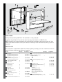
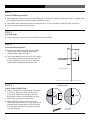
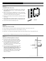
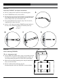
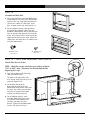
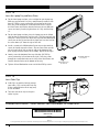
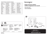
A s s e mbly instructions
eNook Pro
®
Product
Part#
eNook Pro for Laptops, 28w
EPL2818zz/xx
eNook Pro for Laptops, 36w
EPL3616zz/xx
eNook Pro for Monitors, 28w
EPM2818zz/xx
eNook Pro for Monitors, 36w
EPM3616zz/xx
Anthro Corporation® | 10450 SW Manhasset Dr. | Tualatin, OR 97062
Toll-free: 800.325.3841 | Fax: 800.325.0045 | email: [email protected] | anthro.com
Outside the U.S. | Tel: 503.691.2556 | Fax: 503.691.2409
Rev C, May 2009
13
16
01
02
15
14
08
11
05
12
10
09
06
07
04
welcome
Thank you for purchasing eNook® Pro! This installation is a two-person job.
If you have any questions or if we can help you in any way, please contact us at 800.325.3841.
NOTE: We provide do-it-yourself hardware and instructions for installation to wood studs and dry wall. Your
eNook can be mounted to other surfaces (like concrete and brick), and this work should be done by a qualified
contractor.
PA RTS LIST
These instructions are for Anthro’s eNook® Pro. Before beginning assembly, please take a moment to review the
parts list below to verify that your shipment is complete.
Product
Quantity
01 Back Frame
1
36w, Monitor & Laptop Versions
28w, Monitor & Laptop Versions
02 Main Unit
1
36w, Monitor & Laptop Versions
28w, Monitor & Laptop Versions
03 1-5/8" Screw (Not Shown)
4
04 1-1/2" Screw 4
05 Workstation Screw
Laptop Version
6
Monitor Version
4
06 Cable Clips
6
07 Toggle Bolt Anchor
4
08 5/32" Anthro Hex Driver
(not shown)
1
09 Laptop Tray (Laptop Version)
36w
28w (not shown)
1
1
10 Cover Plate (36w Laptop Version) 2
Part Number
Product
Quantity
Part Number
ADDITIONAL COMPONENTS FOR MONITOR VERSION
225-2802-23 11 Keyboard & Mouse Keeper
225-2815-23 (Monitor Version)
1
36w
28w
835-5258-00 835-5259-00 12 Monitor Bracket (Monitor Version) 1
325-5086-00 325-5358-00 225-2823-00
225-2803-23
36w
28w
225-2808-00
225-2810-00
4
325-5092-00 13 3/8" Phillips Screw
14 Rubber Grommet (Monitor Version) 1
325-5150-00
15
175-5217-00 325-5394-00 375-5000-00 225-2811-00 16
225-2816-00 825-3491-00
225-2814-00
VESA Plates Kit
Contains:
75mm VESA Plate (1 ea)
100mm VESA Plate (1 ea)
M4 x .7 x 8mm Screws (4 ea)
M4 x .7 x 13.5mm Screws (2 ea)
Hex Keys (3 ea)
1
Monitor Tilt & Pivot Mount
1
(includes two Phillips mounting screws)
175-5237-00
575-5035-00
STE P 1
Select the Mounting Location
¡ When choosing the right place to install your eNook, be sure to check the location of your power source. The power cord
on the optional medical-grade power strip (p/n 935PG) is 6 ft long.
¡ Your eNook can be mounted to drywall or to wood wall studs. If you’re installing to wood wall studs, go to Step 2.
¡ If you’re installing into drywall, go to Step 7.
STE P 2
Find Wall Studs
¡ Using a stud finder, locate the studs to which you'll attach your eNook.
STE P 3
Determine Mounting Point
¡ Determine the optimal desk height for your eNook.
Typical sitting height is about 29" high; typical
standing height is about 42" high.
14.75"
23"
¡ For the 36w eNook Pro, measure up 14-3/4" from the
shelf location and mark that point on one stud. For
the 28w eNook Pro, measure up 14-1/4" from the
shelf location and mark that point on one stud.
36w version shown
STE P 4
Wall Stud Profile
Attach Screws to Wall Studs
¡ Using a 1/8" drill bit, drill one hole into a stud about
1-1/2" deep. How do you make sure that hole is
1-1/2" deep? Measure that length on your drill
bit and mark it with a piece of masking tape. Stop
drilling when you reach the masking tape.
1½"
¡ Using a Phillips driver (or a power driver with a
Phillips bit), attach the first 1-1/2" long screw at that
mounting point, but don’t tighten all the way to the
wall. Stop tightening when the screw head is about
1/4" away from wall.
eNook® Pro Assembly Instructions
¼"
Tape
Drill
Screw
1-1/2" screw
325-5358-00
STE P 5
Lift eNook Frame onto screws
¡ Lift the eNook frame onto the first mounting screw. Keyhole slots
on the frame are spaced every 2", so you can position the eNook
where you want it.
¡ While one person holds the eNook frame level, the second person
marks the installation point of the second 1-1/2" long screw. Make
sure that the second screw goes into a stud, too!
¡ Remove the frame from the wall and drill the second hole with the
1/8" drill bit.
¡ Using a Phillips driver, attach the second 1-1/2" long screw. Stop
tightening when the screw head is abut 1/4" away from the wall.
¡ Lift the frame onto the two mounting screws.
1-1/2" screw
325-5358-00
STE P 6
Attach Lower Screws to Studs
¡ Once the frame is on the wall, mark the mounting points for lower screws into the same studs.
¡ Using the 1/8" drill bit, drill one hole in each stud about 1-1/2" deep.
¡ Attach the 1-1/2" long screws and tighten all four screws fully so that the Frame is snug against the wall.
Proceed to Step 11 for Monitor version; proceed to Step 12 for the Laptop version.
STE P 7
Determine the Mounting Point on Drywall
¡ Determine the optimal desk height for the eNook
work surface, refer to image for typical shelf heights.
¡ For the 36w eNook Pro, measure up 14-3/4" from
the shelf location and mark that point. For the
28w eNook Pro, measure up 14-1/4" from the shelf
location and mark that point.
¡ Once you determine the right height for your eNook
mark one mounting point hole location. When
choosing the first mounting point, remember that the
two upper mounting points should be at least 16"
apart to keep the eNook stable. To help you visualize
where eNook will be on your wall, use the eNook
Frame as a template.
14.75"
23"
36w version shown
Questions? Call us at 800.325.3841 or visit anthro.com. We’re happy to walk you through the assembly!
STE P 8
Install one TOGGLER™ for Drywall Installation
¡ Drill 1/2” diameter hole in your wall at the mounting point.
A
¡ Insert a TOGGLER into a hole, metal end first.
¡ Pull the plastic ring end so the metal channel rests flush behind the
wall. With your other hand, slide the plastic cap along the straps
until the flange of the cap is flush with the wall.
¡ Place your thumb between the plastic straps. Push side to side,
snapping off the straps at the wall.
¡ Insert a 1-5/8" long screw into the TOGGLER, but don’t tighten all
the way. Leave the bolt head about 1/4” from the plastic cap.
1-5/8" screw
325-5086-00
B
C
D
STE P 9
Install remaining TOGGLERs
This is a two-person step!
¡ Lift the eNook Frame onto the bolt. Using a level to make sure that
the Frame is level, mark the second mounting point as shown. Be
sure that you mark your spot in the center of the small keyhole!
¡ Mark the third and fourth mounting points along the bottom hole
array. Set aside the Frame.
¡ Drill 1/2” diameter holes on the 2nd, 3rd, and
4th mounting points and install TOGGLERs as instructed above.
eNook® Pro Assembly Instructions
STE P 10
Insert Screw and Install Frame
¡ Insert one 1-5/8" long screw into the top two TOGGLERs, but don’t tighten all the way. Leave the screw head about
1/4" from the plastic cap.
¡ Lift the Frame onto the top two screws. Install the bottom two screws, then tighten down all four screws.
For Monitor version, go to Step 11. For Laptop version, go to Step 12.
STE P 11 -a
Attach the Monitor Assembly to the Monitor Rail
¡ Select the 75mm or 100mm VESA bracket that matches the hole
pattern on the back of your monitor.
¡Place the VESA plate in position in back of the monitor with the
cut-out toward the top of the monitor. Using a Phillips screwdriver,
attach the plate to the monitor with the four short fasteners
packaged with the VESA plate.
¡Attach the Monitor Tilt and Pivot Mount to the VESA plate so
that the tab on the top of the mount goes into the slot on the top
of the plate. Secure using two 7.5mm screws using the Phillips
screwdriver.
¡Orient the Monitor Rail so that the vertical hole array is at the
top. Align the two holes on the back of the Monitor Pivot Mount
with two holes on the Monitor Rail so the monitor is at the desired
height, allowing enough space for your monitor to fit inside the
enclosure. Secure the Monitor Assembly to the Monitor Rail with
the two screws that came with the Monitor Pivot Mount.
VESA Plate
Monitor Tilt and Pivot Mount
Monitor Rail
¡ If you purchased a second Monitor Rail, assemble it now.
STE P 11 - b
Install the Monitor Rail onto the Back Frame
¡Determine the installation point of your Monitor Rail.
¡Align the top of the Monitor Rail with the hole array at the top of
the Back Frame so that your monitor is where you want it. Attach
the Monitor Rail to the third row of holes frm the back of the
frame, in any left-to-right position. Use the Phillips screwdriver
and two 3/8" Phillips screws. Next align the bottom of the Monitor
Rail with the hole array at the bottom of the Back Frame. Attach
using two more 3/8" Phillips screws.
¡ If you have a second Monitor Rail, install it now.
3/8" Phillips hd screw
325-5150-00
Questions? Call us at 800.325.3841 or visit anthro.com. We’re happy to walk you through the assembly!
STE P 1 2
Assemble the Main Unit
¡ Using your Hex Driver, install two Workstation
Screws onto the side walls at the top, but don’t
tighten all the way. Stop tightening when the
screw head is about 1/2" from tight. If you
have a Laptop version, skip ahead to Step 13.
¡ Slip the grommet into the cable opening at
the back of the Keyboard Cubby. Place the
Keyboard Cubby onto the shelf so that the logo
faces up and the cable opening faces the back
of the unit. Align the holes at the back of the
cubby with the divets on the shelf. Attach the
cubby to the shelf with three 1/2" Wood screws
using the Anthro driver.
Workstation Screw
325-5092-00
1/2" Assembly screw
325-5008-00
STE P 1 3 - t h i s s t ep r e q u i r e s two p eop le
Attach Main Unit to Frame
NOTE: eNook Pro can be installed at your choice of depth:
7.25" or 8.25" deep. Determine the desired depth before
beginning this step.
¡ Open the top door and find the angle
slots on the Back Frame.
The front set of angled slots is for
8.25" overall depth; the back set is for
an overal depth of 7.25"
¡ Lift the Main Unit onto the
Back Frame by aligning the two
Workstation Screws on the frame with
the angle slots. Make sure that both
fasteners are captured. For Laptop
versions, skip ahead to Step 14.
¡For the Monitor versions, install
two more Workstation Screws into
the sidewalls at the bottom of the
enclosure, just above the shelf
bracket. Tighten all four Workstation
Screws. Skip ahead to Step 15.
eNook® Pro Assembly Instructions
STE P 1 4
Insert the Laptop Tray and Cover Plates
¡ For the 28w Laptop versions, select a height for your laptop tray.
While one person holds it in place, another loosely attaches with
four 3/8" Phillips screws, two on the left and two on the right.
Drive the screws through the ventillation holes on the sides of
the Back Frame and into the threaded holes on the tray. When all
screws are loosely installed, tighten them all. Skip ahead to Step
15.
¡ For the 36w Laptop versions, place the laptop tray on the eNook
shelf so that the logo on the tray faces out. Slide the tray back and
into place. Loosely secure the top of the tray with two Workstation
screws, one on the left and one on the right, but leave the head of
the screw about 1/2" from the edge of the unit.
¡Install a second pair of Workstation Screws next to the two that
secure the laptop tray to the frame. Slip one Cover Plate over the
pair of screws on the left so that the tabs at the bottom of the
plate engage with the notches in the cubby. Repeat on the right.
¡Loosely secure the bottom of the tray with four 3/8" Phillips
screws, two on the left and two on the right. Drive the screws
through the ventillation holes on the sides of the Back Frame and
into the threaded holes on the bottom of the tray.
¡Tighten all four Workstation screws and all four Phillips screws.
3/8" Phillips hd screw
325-5150-00
Workstation Screw
325-5092-00
STE P 1 5
Insert Cable Clips
¡ Cable Clips are provided to help manage
your cables. Clips can be poked into any
of the ventilation holes on the top, back,
or side of eNook.
¡ Twist the ends of the clips to keep the
cables in place.
con gr at u l at i o n s ! yo u r En ook p ro assembly is com p lete!
*300-5455-00*
300-5455-00
Warranty:
eNook has a five year warranty.
Notices:
Technology Furniture and eNook are trademarks of Anthro Corporation. Patent Pending. Anthro reserves the right to modify the design and specifications without prior notice.
Questions? Call us at 800.325.3841 or visit anthro.com. We’re happy to walk you through the assembly!