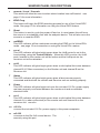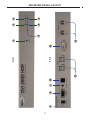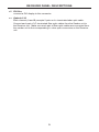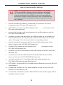
1
®
EXT-DVI-3600HD
User Manual
www.gefen.com
ASKING FOR ASSISTANCE
Technical Support:
Telephone
Fax
(818) 772-9100
(800) 545-6900
(818) 772-9120
Technical Support Hours:
8:00 AM to 5:00 PM Monday through Friday, Pacific Time
Write To:
Gefen Inc.
c/o Customer Service
20600 Nordhoff St
Chatsworth, CA 91311
www.gefen.com
[email protected]
Notice
Gefen LLC reserves the right to make changes in the hardware, packaging and
any accompanying documentation without prior written notice.
DVI 3600 HD is a trademark of Gefen LLC
© 2012 Gefen LLC., All Rights Reserved
All trademarks are the property of their respective companies
Rev A2
CONTENTS
1
Introduction
2
Operation Notes
3
Features
4
Sender Panel Layout
5
Sender Panel Descriptions
7
Receiver Panel Layout
8
Receiver Panel Descriptions
10 Connecting the DVI 2600HD
11
Wiring Diagram
12 Operating the DVI 3600 HD
12
Virtual EDID Programming Procedure
13
Operating Modes
14 Specifications
15 Warranty
INTRODUCTION
Congratulations on your purchase of the DVI 3600 HD. Your complete
satisfaction is very important to us.
Gefen
Gefen delivers innovative, progressive computer and electronics add-on solutions
that harness integration, extension, distribution and conversion technologies.
Gefen’s reliable, plug-and-play products supplement cross-platform computer
systems, professional audio/video environments and HDTV systems of all sizes
with hard-working solutions that are easy to implement and simple to operate.
The Gefen DVI 3600 HD
The DVI 3600 HD allows you to operate a single DVI-compliant computer from
two workstations, by extending DVI, USB 2.0, analog audio, and RS-232 from the
computer to the remote workstation. USB peripherals can be placed at either of
the two locations, by the Sender or Receiver unit.
How It Works
The DVI 3600 HD system consists of a Sender and a Receiver unit. The Sender
connects to the computer’s DVI-compliant video card output, analog audio jack,
RS-232 port, and USB port. The DVI 3600 HD Receiver connects to the remote
display and peripherals. Four strands of LC fiber optic cable connect the Sender
and Receiver together.
The DVI 3600 HD has two modes of USB operation. When in local mode, the
computer sees USB devices connected to the Sender. When in remote mode,
the computer sees USB devices connected to the Receiver. Modes are switched
using a switch on the front panel of the Sender.
1
OPERATION NOTES
READ THESE NOTES BEFORE INSTALLING OR
OPERATING THE DVI 3600 HD
CLASS 1 LASER PRODUCT
•
LC terminated fiber optic cables (2 pairs) are required for operation of the
DVI 3600 HD system.
•
The DVI 3600 HD relies on either Virtual DDC or a locally connected display
(on the sender unit) for display information (EDID). In Virtual DDC mode the
Sender unit will store the remotely connected display’s EDID. This EDID will
need to be recorded onto the sender unit. See page 12 for instructions on
using the Virtual DDC feature.
•
When using a local display, ensure that the remote display can display
common resolutions and timings that are in the EDID of the local display.
The reverse applies when using the Virtual DDC mode: The local display in
Virtual DDC mode must be able to accept common resolutions and timings
that are in the EDID of the remote display.
•
This device will accept both singlemode and multimode fiber optic cables.
•
This device will accept both 50μm and 62.5μm multi-mode fiber optic cable
types.
•
Maximum extension with singlemode fiber optic cable is 6,600 feet
(2 kilometers) at 1920 x 1200 (WUXGA).
•
Maximum extension with multimode fiber optic cable is 1,650 feet
(500 meters) at 1920 x 1200 (WUXGA).
2
FEATURES
Features
•
Extends DVI up to 6,600 feet (2000 meters) with singlemode
•
Extends DVI up to 1,650 feet (500 meters) with multimode along with USB,
analog audio, and RS-232
•
Supports video resolutions up to 1920 x 1200
•
Uses four-strand multi-mode LC terminated fiber cables
•
Supports Virtual DDC and DDC2B protocols
•
Supports DDWG standards for DVI compliant monitors
•
Supports USB 2.0 and USB 1.1
•
USB can be switched between the local computer and the remote
workstation
•
Rack-mountable
Package Includes
(1) DVI 3600 HD - Sender unit
(1) DVI 3600 HD - Receiver unit
(1) 6 ft. Dual-link DVI cable (M-M)
(1) 6 ft. USB cable (A-B)
(1) 6 ft. RS-232 cable (M-F)
(2) 12V power supply
(1) Quick Start Guide
3
10
11
12
13
14
15
Back
1
16
Front
2
17
18
3
5
4
7
6
9
8
SENDER PANEL LAYOUT
4
SENDER PANEL DESCRIPTIONS
1
Remote / Local / Console
This switch will allow the user to select which location has USB control. See
page 13 for more information.
2
EDID Prog.
This button will begin the EDID recording process for use of the Virtual DDC
mode. See page 12 for information on using the Virtual DDC feature.
3
Reset
This button is used to cycle the power off and on. In most cases this will force
the source to re-establish a link with the endpoint device. This will also force the
source to re-read the EDID.
4
SelfEDID
This LED indicator will be used when recording the EDID for the Virtual DDC
mode. See page 12 for information on using the Virtual DDC feature.
5
Local
This LED indicator will glow bright green when the USB control is set to the
Local setting (using the Control Switch). When this LED is active, the USB
ports located on the Sender unit will be active and the USB ports on the
Receiver unit will be disabled.
6
Ch B
This LED indicator will glow bright green when a valid optical link exists between
channel B (LC-fiber connectors) on the Sender unit and channel B on the
Receiver unit.
7
Status
This LED indicator will glow bright green when all devices are properly
connected and that both the Sender and Receiver unit are working properly.
8
Power
This LED indicator will glow bright red once the included 12V DC power supply
has been properly connected between the Sender unit and an available
electrical outlet.
9
Ch A
This LED indicator will glow bright green when a valid optical link exists between
channel A (LC-fiber connectors) on the Sender unit and channel A on the
Receiver unit. See #18.
10 12V DC
Connect the included 12V DC power supply to this power receptacle.
11 RS-232
Connects to the RS-232 control device. The DVI 3600 HD
D may be controlled
remotely using this port.
5
SENDER PANEL DESCRIPTIONS
12 Audio In
Connect a 3.5mm mini-stereo cable from the audio source to this jack.
13 Remote
Reserved for future use. This port is not used.
14 USB In
Use the included USB cable to connect the computer to this port. This port will
accept USB 2.0 and USB 1.1 host devices. USB devices can be connected to
the local and remote USB ports. While all ports are available for device input,
only one location, local or remote, can be active at any given time. To switch
control between locations, use the control switch located on the front panel of
the Sender unit.
15 USB Out
Connect up to two USB devices to these ports.
16 Display
Connect a local DVI display to this port. This port is always active and
duplicates the video input signal on the Sender unit. This port is also used
in the Virtual EDID Programming procedure (see page 12).
17 DVI In
Connect a DVI source to this port.
18 Optical A / B
Each channel (A and B) accepts 2 pairs of LC-terminated fiber optic cable.
Connect each pair of LC-terminated fiber optic cables from the Sender unit to
the Receiver unit. Make sure each pair of fiber optic cables are connected from
the Sender unit to the corresponding LC fiber optic connectors on the Receiver
unit.
6
7
8
9
10
11
Back
Front
12
13
1
2
4
3
6
5
RECEIVER PANEL LAYOUT
7
RECEIVER PANEL DESCRIPTIONS
1
Reset
This button is used to cycle the power off and on. In most cases this will force
the source to re-establish a link with the endpoint device. This will also force the
source to re-read the EDID.
2
Remote
This LED indicator will glow bright green when USB control is set to Remote
mode (see page 13). When this LED is active, the USB ports on the Receiver
unit will be active and the USB ports on the Sender unit will disabled.
3
Ch B
This LED indicator will glow bright green when a valid optical link exists between
channel B (LC-fiber connectors) on the Sender unit and channel B on the
Receiver unit (see page 7).
4
Status
This LED indicator will glow bright green when all devices are properly
connected and that both the Sender and Receiver unit are working properly.
5
Power
This LED indicator will glow bright red once the included 12V DC power supply
has been properly connected between the Sender unit and an available
electrical outlet.
6
Ch A
This LED indicator will glow bright green when a valid optical link exists between
channel A (LC-fiber connectors) on the Sender unit and channel A on the
Receiver unit. See #18.
7
12V DC
Connect the included 12V DC power supply to this power receptacle.
8
RS-232
Connects to the RS-232 control device. The DVI 3600 HD
D may be controlled
remotely using this port.
9
Audio Out
Connect an audio/video device to this jack using a 3.5mm mini-stereo cable.
10 Remote
Reserved for future use. This port is not used.
11 USB
Connect up to four USB devices to these ports. These USB ports are active only
when the control switch is set to Remote.
8
RECEIVER PANEL DESCRIPTIONS
12 DVI Out
Connect a DVI display to this connector.
13 Optical A / B
Each channel (A and B) accepts 2 pairs of LC-terminated fiber optic cable.
Connect each pair of LC-terminated fiber optic cables from the Sender unit to
the Receiver unit. Make sure each pair of fiber optic cables are connected from
the Sender unit to the corresponding LC fiber optic connectors on the Receiver
unit.
9
CONNECTING THE DVI 3600 HD
How to Connect the DVI 3600 HD
STOP: The DVI 3600 HD can use a local EDID or a virtual EDID.
To use a local EDID, a display must be connected to the Sender
unit at all times, before powering the DVI 3600 HD. If the EDID
of the remote display (virtual EDID) is to be used, then follow the
instructions on page 12 before continuing. After a virtual EDID has
been programmed, a local display can be connected to the Sender
unit, if desired.
1.
Use the included DVI cable to connect the DVI source to the DVI In
connector on the DVI 3600 HD Sender unit.
2.
OPTIONAL: Connect a local DVI display to the Displayy connector on the
DVI 3600 HD Sender unit.
3.
Connect the included USB cable between the USB host device and the
DVI 3600 HD Sender unit.
4.
Connect up to two USB devices to the USB Out ports on the Sender unit.
These USB devices can only be used if the DVI 3600 HD is set to Local
mode. See page 13 for more information on operating modes.
5.
Use the included mini-stereo cable to connect the audio source to the
Audio In jack on the DVI 3600 HD Sender unit.
6.
Connect a DVI cable from the display to the DVI Outt connector on the
DVI 3600 HD Receiver unit.
7.
Connect up to four USB devices to the USB outputs on the DVI 3600 HD
Receiver unit.
8.
Connect a mini-stereo cable between the audio/video device and the
Audio Outt jack on the DVI 3600 HD Receiver unit.
9.
Connect two pairs of LC-terminated fiber optic cable between the
DVI 3600 HD Sender unit and Receiver unit.
10. OPTIONAL: Connect an RS-232 cable from the Receiver unit to the RS-232
control device.
11. Connect the included 12V DC power supplies to both the DVI 3600 HD
Sender unit and Receiver unit.
12. Connect the included AC power cables between each power supply and an
available electrical outlet.
10
CONNECTING THE DVI 3600 HD
IMPORTANT: When connecting the fiber optical cables, ensure that
each of the fiber optic cables are connected in the correct order,
between the Sender and Receiver unit (1 to 1, 2 to 2, 3 to 3, and 4 to
4) as shown below.
Sender unit
Receiver unit
3
4
2
1
Wiring Diagram for the DVI 3600 HD
FIBER OPTIC (LC-LC) CABLE
RS-232 CABLE
AUDIO CABLE
USB CABLE
DVI CABLE
Computer
Local DVI Monitor
(Up To 6,600 FT)
Receiver
Local USB Mouse
Powered
Speakers
Sender
Local USB Keyboard
DVI Monitor
USB Mouse
USB Keyboard
RS-232 Controller
USB Printer
USB External HDD
EXT-DVI-3600HD
11
OPERATING THE DVI 3600 HD
Virtual EDID Programming Procedure
Virtual DDC mode is the process of recording an EDID from a specified display.
This EDID will be stored and used by the Sender unit to send the correct display
information to the source device.
1.
Make sure that there are no USB, audio, or DVI cables are connected to the
DVI 3600 HD Sender unit. Make sure that the power supply is disconnected.
2.
Connect a DVI cable from the Local Display port (see page 4 and 6) on the
DVI 3600 HD Sender unit to the display at the remote location.
3.
Power-on the display.
4.
Connect the 12V DC power supply to the power receptacle on the Sender
unit. Make sure that the Power LED is ON and that the Status LED is
blinking slowly.
5.
Press and release the EDID Prog
g button on the Sender unit using a
small pointed object. The SelfEDID LED indicator will flash rapidly for
approximately eight seconds. Once the EDID has been successfully
recorded, the SelfEDID LED indicator will turn off.
Sender unit
SelfEDID LED
flashes while
p g
programming
g
Press and hold the
EDID Prog. button
6.
Disconnect the power supply and the DVI cable from the DVI 3600 HD
Sender unit.
7.
Connect the DVI 3600 HD Sender and Receiver unit as outlined on pages
10 and 11.
12
OPERATING THE DVI 3600 HD
USB Operating Modes
The front panel of the DVI 3600 HD Sender unit has a control switch that
determines the location of USB control (Remote or Local). This control switch
does not affect the DVI outputs or RS-232 control. Console mode is not used.
Local
Set the control switch to Locall to access USB control from the Sender unit. Any
USB devices connected to the Receiver unit are disabled.
Computer
Local DVI Monitor
Remote
Local
Console
Receiver
Local USB Mouse
Powered
Speakers
Sender
Local USB Keyboard
DVI Monitor
USB Mouse
USB Keyboard
Active
Disabled
RS-232 Controller
USB Printer
USB External HDD
Remote
Set the control switch to Remote to access USB control from the Receiver unit.
Any USB devices connected to the Sender unit are disabled.
Computer
Local DVI Monitor
Remote
Local
Console
Receiver
Local USB Mouse
Powered
Speakers
Sender
Local USB Keyboard
DVI Monitor
USB Mouse
USB Keyboard
Active
Disabled
RS-232 Controller
USB Printer
USB External HDD
13
SPECIFICATIONS
Maximum Pixel Clock................................................................................165 MHz
Video Input Connector (Sender)................ (1) DVI-D (24 pin), female (digital only)
Video Output Connector (Sender)............. (1) DVI-D (24 pin), female (digital only)
Video Output Connector (Receiver).......... (1) DVI-D (24 pin), female (digital only)
Audio Input Connector (Sender).................................. (1) 3.5 mm mini-stereo jack
Audio Output Connector (Receiver)............................ (1) 3.5 mm mini-stereo jack
USB Host Connector (Sender)....................................................... (1) USB Type B
USB Device Connectors (Sender)..................................... (2) USB Type A, female
USB Device Connectors (Receiver).................................. (4) USB Type A, female
USB Maximum Bandwidth....................................................................... 480 Mbps
RS-232 Port (Sender)................................................................... (1) DB-9, female
RS-232 Port (Receiver)................................................................... (1) DB-9, male
Link Connectors (Sender / Receiver)................................................... (4) Type LC
Remote Connector (Sender / Receiver)........... (1) RJ-11 (reserved for future use)
Power Supply (Sender / Receiver)........................................................ (1) 12V DC
Power Consumption.................................................................... 36W (max.) each
Dimensions (W x D x H) (Sender / Receiver).................................12.4” x 5” x 1.6”
(315mm x 127mm x 41mm)
Shipping Weight................................................................................ 8 lbs. (3.6 kg)
14
WARRANTY
Gefen warrants the equipment it manufactures to be free from defects in material
and workmanship.
If equipment fails because of such defects and Gefen is notified within two (2)
years from the date of shipment, Gefen will, at its option, repair or replace the
equipment, provided that the equipment has not been subjected to mechanical,
electrical, or other abuse or modifications. Equipment that fails under conditions
other than those covered will be repaired at the current price of parts and labor in
effect at the time of repair. Such repairs are warranted for ninety (90) days from
the day of reshipment to the Buyer.
This warranty is in lieu of all other warranties expressed or implied, including
without limitation, any implied warranty or merchantability or fitness for any
particular purpose, all of which are expressly disclaimed.
1.
Proof of sale may be required in order to claim warranty.
2.
Customers outside the US are responsible for shipping charges to and from
Gefen.
3.
Copper cables are limited to a 30 day warranty and cables must be in their
original condition.
The information in this manual has been carefully checked and is believed to
be accurate. However, Gefen assumes no responsibility for any inaccuracies
that may be contained in this manual. In no event will Gefen be liable for
direct, indirect, special, incidental, or consequential damages resulting from
any defect or omission in this manual, even if advised of the possibility of such
damages. The technical information contained herein regarding the features and
specifications is subject to change without notice.
For the latest warranty coverage information, refer to the Warranty and Return
Policy under the Support section of the Gefen Web site at www.gefen.com.
PRODUCT REGISTRATION
Please register your product online by visiting the Register Product page
under the Support section of the Gefen Web site.
15
Rev A2
Pb
This product uses UL or CE listed power supplies.