1
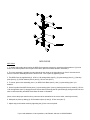
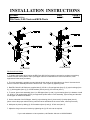
INSTALLATION INSTRUCTIONS
Product
Date
Clevis Assemblies
6-17-99
Form #
INST49
DS-Clevis, 0-90 Clevis and MCS-Clevis
DS-CLEVIS
0-90 CLEVIS
DS-Clevis & 0-90 Clevis
1. To obtain side-to-side swivel motion the DS-Clevis & 0-90 Clevis must be mounted on equipment containing
Gamber-Johnson swivel pattern cutout. (DS-Upper is shown in illustration as it is the most common, other
applications follow same procedure).
2. The clevis assembly is typically mounted with the tilt lock knob on the right side as you face it. Unscrew the tilt
knob to loosen the assembly and set the amount of tilt. Lock in place by tightening knob.
3. Both DS-Clevis & 0-90 Clevis are supplied with (3) .25-20 x 1.00 carriage bolts (item 5), (2) nylon bearings (item
3), (1) backup plate (item 4), (3) .25 flat washers (item 6) and (3) .25 lock nuts (item 7).
4. To mount, place clevis assembly (item 1) on DS-Upper (item 2), with (1) nylon bearing (item 3) in-between. Install
(3) .25-20 x 1.00 carriage bolts (item 5), through three square holes in clevis assembly, nylon bearing and the slots
in DS-Upper as shown in illustration.
5. On the underside of the DS-Upper, install (1) nylon bearing (item 3), then install (1) backup plate (item 4).
(Note: to have the proper swivel motion, parts need to be assembled in the correct order, metal-nylon-metal.)
6. Hold parts in place by adding (3) .25 flat washers (item 6) and (3) .25 lock nuts (item 7).
7. Adjust the drag on the swivel motion by tightening the (3) .25 lock nuts as required.
If you need assistance or have questions, call Gamber Johnson at 1-800-456-6868.
MCS-CLEVIS
MCS Clevis
1. To obtain side-to-side swivel motion the MCS-Clevis must be mounted on equipment with a pattern of (3) in-line
holes, as the swivel pattern cutout is part of the clevis. (MCS Clevis Base shown in illustration).
2. The clevis assembly is typically mounted with the tilt lock knob on the right side as you face it. Unscrew the tilt
knob to loosen the assembly and set the amount of tilt. Lock in place by tightening knob.
3. The MCS-Clevis is supplied with (3) .25-20 x 1.00 carriage bolts (item 5), (2) nylon bearings (item 3), (1) backup
plate (item 4), (3) .25 flat washers (item 6) and (3) .25 lock nuts (item 7).
4. To mount, place clevis assembly (item 1) on MCS Clevis Base (item 2), with (1) nylon bearing (item 3) inbetween.
5. On the top side of the MCS-Clevis place (1) nylon bearing (item 3) and (1) backup plate (item 4). Install (3) .25-20 x
1.00 carriage bolts (item 5), through the three square holes in backup plate & nylon bearings, through center hole and
slots in clevis assembly and MCS Clevis Base as shown in illustration.
(Note: to have the proper swivel motion, parts need to be assembled in the correct order, metal-nylon-metal.)
6. Hold parts in place by adding (3) .25 flat washers (item 6) and (3) .25 lock nuts (item 7).
7. Adjust drag on the swivel motion by tightening the (3) lock nuts as required.
If you need assistance or have questions, call Gamber Johnson at 1-800-456-6868.