1
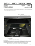
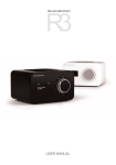
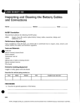
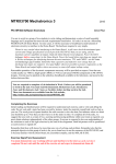
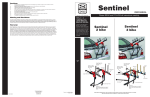
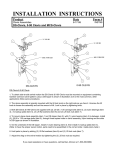
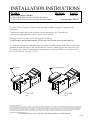
INSTALLATION INSTRUCTIONS
Product
Revision
Work Truck Console w/ File Box
7170-0125 Work Truck Console w/ File Box and Armrest
7170-0164 Work Truck Console w/ File Box and Armrest Printer
Rev.A
Form #
INST-587
Printing Spec: PS-001
The Work Truck Console w/ File Box Kits, provide lockable storage for supplies and
equipment.
A cupholder, radios and control heads can be mounted in the Console box.
Letter size hanging folders can be stored in the File Box.
Carrying cutouts on sides aid in moving and installing.
The Workstation weighs approximatly 50 lbs, use caution when moving and installing.
The units are typically installed between the driver and passenger seats with Console Box
installed toward the front of the vehicle and the File Box openning for the drivers access.
This allows the Vertical Surface Mount and Armrest or Armrest Printer to mounted on the
end of the File Box. See Fig 1 & Fig 2.
Printer Armrest
Armrest
7170-0125
Fig 1
7170-0164
Fig 2
Product Mounting Disclaimer
Gamber-Johnson is not liable under any theory of contract or tort law for any loss, damage, personal injury, special, incidental or consequential damages for personal injury or other damage
of any nature arising directly or indirectly as a result of the improper installation or use of its products in vehicle or any other application. In order to safely install and use Gamber-Johnson
products full consideration of vehicle occupants, vehicle systems (i.e., the location of fuel lines, brakes lines, electrical, drive train or other systems), air-bags and other safety equipment is
required. Gamber-Johnson specifically disclaims any responsibility for the improper use or installation of its products not consistent with the original vehicle manufactures specifications
and recommendations, Gamber-Johnson product instruction sheets, or workmanship standards as endorsed through the Gamber-Johnson Certified Installer Program.
© copyright 2012 Gamber-Johnson, LLC
If you need assistance or have questions, call Gamber-Johnson at 1-800-456-6868
1 of 4
There are two ways to install and attach the Console and File Box Kits to the vehicle floor.
The first requires drilling holes into the vehicle floor, the second uses the existing seat bolts:
#1 - The Console and File boxes can be attached directly to the vehicle floor.
Mounting holes are provided in the bottom of each.
(Customer to supply nescessary hardware).
The height and angle of the Console Box can be adjusted if needed, to allow 2.4" of vertical
adjustment or to compensate for an uneven vehicle floor, by removing the (4) .25-20 x .50
Button Head Screws from the sides of the Console Box, repositioning the slots on the
Console Box with the threaded inserts on the Console Base and reinstalling the Button Head
Screws. See Fig 3.
Position the Workstation in vehicle.
Depending on vehicle used and desired location, a center console or seat section may need
to be removed.
Check that the location chosen does not interfere with the proper operation of or cause damage
to - wiring, fuel or hydraulic lines, the exhaust system or drive train components and vehicle
controls like gear shift lever, airbag sensors or airbag deployment zone.
Using the Console and File Box as templates, mark the mounting hole location on the
vehicle floor.
Drill mounting holes thru vehicle floor.
.25-20 grade 5 bolts, flat washers, lock washers and hex nuts are recommended.
#2 - If drilling into the vehicle floor is not possible, the Console and File Box may also be
attached to a Gamber-Johnson MCS Long or Short Top Plate & Vehicle Specific Leg kit.
Check with Gamber-Johnson if a Vehicle Leg kit and Top Plate are available for your
application.
Leg kits are typically installed by removing one or two of the bolts securing the driver and
passenger seats, inserting leg kit between seat bracket and vehicle floor, reinstalling the
seat bolts.
Specific instructions are supplied with each leg kit.
The Console and File Box are then bolted to the Top Plate using .25-20 x 1.00 Carriage Bolts,
.25 Lock Washers, .25-20 Hex Nuts.
2 of 4
Install the control heads, accessories and blank panels into the console box.
Assemble faceplates to control heads as described in instruction sheet INST-3. (see page 4)
Electrically connect the equipment at this time, allowing extra wire length for servicing the
equipment.
File Box
Console Box
Armrest or
Armrest Printer
2.4"
Adjustment
.25-20 x .50
Button Head Screws
Insert (4) .25-20 x .75 Carriage Bolts
from inside of File Box
Fig 3
Vertical Surface Mount
(4) .25 Flat Washers
(4) .25-20 Nylok Nuts
The Vertical Surface Mount is attached to the end of the File Box.
(4) .25-20 x .75 Carriage Bolts are inserted from the inside of the File Box and (4) Flat Washers
and (4) Nylok Nuts installed on the outside.
The Armrest or Armrest Printer is inserted and secured in position by tightening the 3/8 bolt.
See Fig 3
3 of 4
INSTALLATION INSTRUCTIONS
Product
Date
Faceplates
02/23/01
Form #
INST3
ASSEMBLING MCS FACEPLATES: (Refer to figure 1)
1. Check that the following pieces are present:
Dual lock fastener (supplied w/console box)
(1) faceplate vertical offset
(1) faceplate top bracket
(1) flat washer #6
(1) 6-32 nut
2. For each faceplate, slide the faceplate vertical offset
(item 1) on the stud in faceplate top bracket (item 2).
Add flat washer (item 3) and hex nut (item 4). Remove
the extra strips of dual lock fastener pressed onto each
console box under holddown rails, cut to same length as
each faceplate, remove protective film covering the
adhesive strip and apply to top bracket as shown.
3. If the faceplates are being mounted in an older style MCS Console Box (those with threaded inserts on the
top surface of the side panels/holddown screws passing through slots in existing face plates or blank
panels), DO NOT attach the strip of dual lock fastener on each faceplate as described above. When
installing faceplates into these MCS Console Boxes, mark any that cover the threaded inserts and drill a .312
diameter clearance hole as shown in Figure 1.
ASSEMBLING MCS FACEPLATES TO CONTROL HEADS AND INSTALLING IN MCS CONSOLE BOXES (Refer to figures
2 & 3).
1. Install the faceplates on each control head as shown in figure 2. Adjust the faceplates so the mounting
holes in the sides of the control head line up in the slots of the faceplate vertical offsets and so the desired
amount of the control head will extend from the console. Make sure to allow enough room underneath for
any connectors that may be required. Test the fit of each control head, the tallest heads may need to be
installed near the higher end of the console.
2. Arrange the control heads in the console box as desired. Blank panels of various sizes have been provided to
act as spacers between each control head, if needed. Secure in place by attaching a piece of dual lock
fastener to each end of the blank panel and then pressing the strips of dual lock fastener on the faceplates,
blank panels and console box together.
3. Attach the MCS Console Box holddowns to the sides of the console box and over faceplates with (6) 10-32 x
.38 Phillips head machine screws.
4 of 4